
Related Manuals for TeeJet Technologies 844E


Summary of Contents for TeeJet Technologies 844E
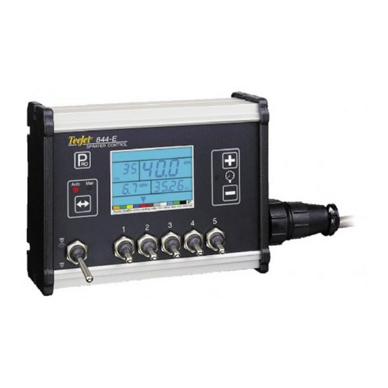
- Page 1 S P R A Y E R C O N T R O L Installation, Programming, and Operating Manual...
-
Page 2: Table Of Contents
844E Sprayer Crontrol Table of Contents INTRODUCTION MOUNTING SPRAYER COMPONENTS Pressure Regulator in Bypass Mode ..................3 Pressure Regulator in Throttling Mode ................5 Flow Meter ..........................6 Boom Control Valves ......................6 Pressure Transducer ....................... 6 INSTALLING THE SPEED SENSOR ASSEMBLY Components .............................. - Page 3 844E Sprayer Control PROGRAMMING GUIDELINES IMPORTANT PRELIMINARY INFORMATION Steps to Successful Programming ..................19 PROGRAMMING THE 844E SPRAYER CONTROL SYSTEM SYSTEM SETUP MODE Program Units ........................20 Setting Your Program Mode (U.S., Turf, NH , Imperial, S.I.) ..............20 Reset Defaults ........................20 Reset To Default Settings .........................
- Page 4 844E Sprayer Crontrol Calibrate Speed ........................27 Speed Sensor Calibration ......................... 27 Proximity/Magnetic Pulses ........................27 Automatic Calibration: ..........................28 Manual Calculation: ............................. 28 Radar Speed Pulses ......................29 Automatic Calibration: ..........................29 Manual Calculation: ............................. 29 Distance Counter ........................29 Simulated Ground Speed .....................
- Page 5 844E Sprayer Control FEATURES Boost Mode ........................... 39 Area/Volume Feature ......................39 Flow Rate Feature ......................... 40 Application Alarm......................... 40 No Flow Alarm ........................40 Printing ..........................41 TROUBLESHOOTING GUIDE FLOW METER CALIBRATION Method 1 – Known Volume ....................48 Step 1 –...
- Page 6 E SPRAYER CONTROL Copyrights © 2011 TeeJet Technologies. All rights reserved. No part of this document or the computer programs described in it may be reproduced, copied, photocopied, translated, or reduced in any form or by any means, electronic or machine readable, recording or otherwise, without prior written consent from TeeJet Technologies.
-
Page 7: Introduction
844E Sprayer Control INTRODUCTION Congratulations! And thank you for choosing TeeJet Technologies’ advanced 844 sprayer control system. With its proper installation and maintenance, you can enjoy many seasons of accurate and uniform spray application with fi ngertip convenience and ease of operation. -
Page 8: Mounting Sprayer Components
844E Sprayer Crontrol MOUNTING SPRAYER COMPONENTS Pressure Regulator in Bypass Mode All pressure regulating valves for the 844 will be wired for use in a by-pass system. While plumbed in a by-pass mode, with the Auto/ Man key in the “MAN” mode, the valve should close when the key is pressed and open when the key is pressed. - Page 9 844E Sprayer Control Figure 1-1: Bypass Plumbing Diagram - Pressure Based System Figure 1-2: Bypass Plumbing Diagram - Flow Based System www.teejet.com...
-
Page 10: Pressure Regulator In Throttling Mode
844E Sprayer Crontrol Pressure Regulator in Throttling Mode The pressure regulating valve, as shown in the fi gures below, can be located in the supply line before the boom control valves. If you choose this location, the 844 will need to be properly programmed to reverse the polarity of the valve. -
Page 11: Flow Meter
844E Sprayer Control Flow Meter To ensure accurate readings, the fl ow meter (if used) must be mounted 10″ to 12″ (25-35 cm) from other pipe fi ttings, preferably in a vertical position with the fl ow going up. It should also be mounted with the direction of fl... -
Page 12: Installing The Speed Sensor Assembly
844E Sprayer Crontrol INSTALLING THE SPEED SENSOR ASSEMBLY Components Two (2) magnets, Sensor with attached connector cable, and mounting hardware. If you are installing a radar ground speed sensor, follow the instructions supplied with that unit. Speed Step 1 - Location The speed sensor assembly should be installed on a non-driven wheel to avoid potential errors that are likely to occur from a slipping drive wheel. -
Page 13: Speed Step 2 - Installing The Wheel Magnets
844E Sprayer Control Speed Step 2 - Installing The Wheel Magnets Check for pre-drilled holes in the wheel rim. If pre-drilled holes are not available, layout a pattern as shown in Figure 1-7 and drill two 3/8″ (10 mm) holes near the outer edge of the rim if possible, and 180° from each other. -
Page 14: Speed Step 3 - Installing The Magnetic Sensor
844E Sprayer Crontrol Speed Step 3 - Installing the Magnetic Sensor The fl at, pressed L bracket of the wheel speed sensor kit should be secured to a vertical member near the non-driven wheel. The round, right angle steel bracket is then secured to the fl at bracket with the two U-bolts and necessary hardware provided. -
Page 15: Speed Step 4 - Confi Rming Speed Sensor Installation
844E Sprayer Control Speed Step 4 - Confi rming Speed Sensor Installation Magnetic Wheel Sensor After your wheel or proximity sensor is installed and once the 844 console is installed and powered up, you can test the speed sensor installation. Connect the wheel speed or proximity sensor to the sensor cable, and in turn connect the sensor cable to the 844 console. -
Page 16: Mounting The Teejet 844 Console
844E Sprayer Crontrol MOUNTING THE TEEJET 844 CONSOLE Console Step 1 - Location Determine the best location for the control console in the cab or operator’s compartment. Allow suffi cient clearance, approximately 4-5″ (10-12 cm) to accommodate for the cable that will be connected to the right side of the console. -
Page 17: Console Step 3 - Power Connection
844E Sprayer Control Console Step 3 - Power Connection Locate the power cable that has a black connector on one end and two battery terminal rings on the other. Extend the battery terminal ring end of this cable from the cab to the battery. - Page 18 844E Sprayer Crontrol Figure 1-12: Power Connection 98-70006 R3...
-
Page 19: Console Step 4 - Connecting Component Cables
844E Sprayer Control Console Step 4 - Connecting Component Cables Now that you have the console installed you can begin connecting it to the other components of the 844 system. The standard kit contains a main cable that attaches to the boom control valves, the pressure regulating valve, fl... -
Page 20: Connect Step 1 - Wiring Layout
844E Sprayer Crontrol Connect Step 1 - Wiring Layout Determine the best cable routing to the sprayer control components on the sprayer. This may be along the fl ow line, main frame of the sprayer, or wherever the cables can be conveniently secured. Avoid any situation where the cables may lay in puddles, or come in contact with extreme heat sources. -
Page 21: Connect Step 2 - Making The Connection
844E Sprayer Control Connect Step 2 - Making The Connection Now, extend the cable leads to the Flow meter or Pressure Sensor, and Wheel Sensor or Radar Sensor to the furthest component. Select the appropriate lead and connect to this component. Run the cable to the other component, taking care to safely secure the cable along the route. - Page 22 844E Sprayer Crontrol Figure 1-16: Power Connector Power Connector Pin No. Wire Color Signal Name Brown +12 VDC (Computer) Blue +12 VDC (Valves) Yellow/Green Ground Figure 1-17: Speed Sensor Connector Speed Sensor Connector Pin No. Wire Color Signal Name Brown...
- Page 23 844E Sprayer Control Figure 1-20: Regulator Connector Regulator Connector Pin No. Wire Color Signal Name Brown Power Out White Speed Signal NOTE: The 844 is designed to handle a maximum of 4 amps per boom section. You are now ready to begin the programming of the TeeJet 844 Sprayer Control.
-
Page 24: Programming Guidelines
844E Sprayer Crontrol PROGRAMMING GUIDELINES IMPORTANT PRELIMINARY INFORMATION Before you begin, we recommend that you review the following Programming Guidelines that control the programming process: • For your convenience, the programming of the 844 has been divided into two programming categories;... -
Page 25: Programming The 844E Sprayer Control System
844E Sprayer Control PROGRAMMING THE 844E SPRAYER CONTROL SYSTEM SYSTEM SETUP MODE The System Setup Mode contains the programming steps that customize the controller to the sprayer or sprayer components. These include calibration steps and parameters that, once programmed, will likely never change. -
Page 26: Sensor Type
844E Sprayer Crontrol Sensor Type Flow Meter or Pressure Based Default = FLO The 844 system can be used with either a fl ow meter, pressure transducer or both. This step tells the computer which sensor you will be using on your sprayer to control the fl ow regulation. -
Page 27: Pressure Transducer
844E Sprayer Control Pressure Transducer Maximum rating (P Hi) Default = 150 (PSI in US, trF and I P Modes) Default = 10. 0 (bar in Si Mode) This step is used to set the maximum rating of the pressure transducer in your system. This number can be found stamped on the pressure transducer itself. -
Page 28: Nozzle Spacing
844E Sprayer Crontrol Nozzle Spacing Default = 20 (inches in US, trF, and INP Modes) Default = 50 (centimeters in Si Mode) Default = 30 (inches in nh3 Mode) While in the Nozzle Spacing step, the symbol will be fl ashing at the top of the console display. Nozzle spacing should be recorded in inches (cm in SI mode). -
Page 29: User Program Tip
844E Sprayer Control User Program Tip User Programmable Tip Default = 0. 0 0 While in the User Programmable Tip step, the symbol will be fl ashing above the tab at the bottom of the display. In some cases you may fi nd that nozzles other than those pre-programmed for the 844 Sprayer Control will need to be used. -
Page 30: Pressure Regulation
844E Sprayer Crontrol Pressure Regulation Pressure Regulation Mode Default = byp (By-pass for US, trF, I P, and Si Modes) Default = thr (Throttling for nh3 Mode) While in the Pressure Regulating Mode step, the symbol will be fl ashing at the top of the console display. -
Page 31: Regulation Adjustment Speed
844E Sprayer Control Regulation Adjustment Speed Coarse Regulation Adjustment Speed Default = 9 While in this step, the symbol will be fl ashing at the top of the console display. This step allows you to regulate the speed of the pressure regulating valve to accommodate different application needs. -
Page 32: Control Valve Type
844E Sprayer Crontrol To accept this value and advance to the next step, press the key. NOTE: This speed value can be adjusted to optimize system performance. If you notice that the valve seems to “search” for the programmed application rate by cycling the pressure up and down continuously, reduce the number until the “searching”... -
Page 33: Automatic Calibration
844E Sprayer Control Automatic Calibration To automatically calibrate the speed sensor, mark off a distance of exactly 300 ft / 100 m. While still in the speed calibration program step, position your sprayer at the beginning of your 300 ft / 100 m course and press the keys simultaneously to clear the contents of the display and to activate the auto calibration mode. -
Page 34: Radar Speed Pulses
844E Sprayer Crontrol Radar Speed Pulses Automatic Calibration: The automatic calibration of a Radar speed sensor is similar to the automatic calibration of a wheel speed sensor. Refer to the directions above. When the console has determined that a Radar Speed Sensor is being used, rAd will be displayed in the lower left of the console display. -
Page 35: Program Specifi C Gravity
844E Sprayer Control Program Specifi c Gravity Weight of Solution Per Gallon Specifi c Gravity Liquid Specifi c Gravity (Density) 7.0 lb 0.84 Default = 1. 0 0 8.0 lb 0.96 While in the Liquid Specifi c Gravity (Density) 8.34 lb - water 1.00... -
Page 36: Communications
844E Sprayer Crontrol Communications Default = no CO (no communications) This step lets you select what type of communication you will be using. The choices available are the default of “no CO ” (no communications), “prt” (Printing Capability), “gps” (Global Positioning Communication Capability), or “lOg”... -
Page 37: Application Setup Mode
844E Sprayer Control APPLICATION SETUP MODE The Application Setup Mode contains the programming steps that are most frequently changed (target application rate, and nozzles used). Spraying Systems Co. has added this separate setup mode to speed the programming process when minor changes are made in the spraying operation (i.e. changing fi elds, switching nozzles, changing crops, etc.). -
Page 38: Nozzle Selection
844E Sprayer Crontrol Nozzle Selection Default = Red or 0.4 US GPM (1.29 l/min) {0.33 Imperial GPM} While in the nozzle selection step, the display will remain the same as in the Target Application Rate step except symbol will be fl ashing at the bottom of the display just above a color coded strip. - Page 39 844E Sprayer Control Feature: Based on the tip programmed and nozzle spacing (programmed in the System Setup Mode), the 844 console will calculate the required speed to achieve the application rate that was entered in the last programming step. The speed will be displayed in the lower left corner of the display window.
-
Page 40: Calculation Troubleshooting
844E Sprayer Crontrol Calculation Troubleshooting This Programming Step is a diagnostic tool only This programming step has no effect on the operation of the TeeJet 844 Sprayer Control. It allows the user to adjust the indicated pressure to see what effects it would have on the operating speed; or the user can adjust the speed to see what pressure would need to be used to maintain the target application rate. - Page 41 844E Sprayer Control NOTE: If you are going to be spraying with a different density of liquid other than water and you have programmed that specific gravity (density) into the Specific Gravity (Density) Step in the System Setup Mode, you must select the symbol at the top of the display in order for all of the calculations to be performed in the regular spraying mode.
-
Page 42: Operating Instructions
844E Sprayer Crontrol OPERATING INSTRUCTIONS SPRAYER CHECKOUT Before spraying, check all connections related to the Sprayer Control assembly. Particular attention should be given to the speed sensor to be sure the sensor and magnets are in line, and properly secured. -
Page 43: The Spraying Operation
844E Sprayer Control THE SPRAYING OPERATION You have fi lled the sprayer tank and have thoroughly mixed the chemical(s).Your application rate has been determined as well as the spray tip you will be using, with the sprayer data programmed into the computer. -
Page 44: Features
844E Sprayer Crontrol FEATURES Boost Mode There may be instances where ”on the go” increased or decreased chemical application may be required in certain areas of your fi eld. In situations like this, the keys will allow you to easily make the necessary adjustments. -
Page 45: Flow Rate Feature
844E Sprayer Control Flow Rate Feature The 844 Sprayer Control will measure a fl ow rate moving through the fl ow meter in GPM (LPM) {Imp GPM}. This feature is activated by pressing and holding the key while spraying in the normal operating mode. The fl ow rate display replaces the area/volume display in the lower right portion of the display. -
Page 46: Printing
844E Sprayer Crontrol Printing Optional printers are available for printing a spraying report directly from the 844. The optional printers are available through your TeeJet supplier. The printout that you get from the 844 contains memory information that the 844 collects. A sample of this printout is below. -
Page 47: Troubleshooting Guide
844E Sprayer Control TROUBLESHOOTING GUIDE CONDITION POSSIBLE CAUSE SOLUTION Check all components and programming Application Rate Units (GPA, G/1000 Continuous discrepancy of 10% or steps related to fl ow I/Ha) continually fl ash on/off more between Target Application Rate and Actual Application Rate... - Page 48 844E Sprayer Crontrol CONDITION POSSIBLE CAUSE SOLUTION Check all components and programming Application Rate Units continually Continuous discrepancy of 10% or steps related to fl ow fl ash on/off more between Target Application Rate and Actual Application Rate MECHANICAL Make sure there is no pressure in the Stalled fl...
- Page 49 844E Sprayer Control CONDITION POSSIBLE CAUSE SOLUTION Check the pump to make sure it is Pump capacity too low working correctly. Check the plumbing system for any obstructions. Reduce Agitation Volume. Some centrifugal pumps provide more Pump capacity too high fl...
- Page 50 844E Sprayer Crontrol CONDITION POSSIBLE CAUSE SOLUTION Due to very low application rates (GPA, Rate oscillation Extreme low regulated fl ow G/1000 ft ), (l/Ha) the regulating valve in throttling mode is operating in an almost closed position. Adjust the Reg. Valve Speed Number in the System Setup Mode (page 27) to a slower value.
- Page 51 844E Sprayer Control CONDITION POSSIBLE CAUSE SOLUTION Recalibrate the magnetic or radar speed Application Rate Units (GPA, G/1000 Speed sensor not calibrated correctly pulses in the Calibrate Speed section of I/Ha) continually fl ash on/off the System Setup Mode on page 18-19...
- Page 52 844E Sprayer Crontrol CONDITION POSSIBLE CAUSE SOLUTION One or more of the wheel sensor Speed sensor installed incorrectly magnets are not consistently sending a pulse to the monitor. The distance between the sensor and the magnets is incorrect. Ground debris can accidentally move the sensor out of position.
-
Page 53: Flow Meter Calibration
FLOW METER CALIBRATION The fl ow meter supplied with your system has been calibrated at the factory and under normal circumstances there may be no need to re-calibrate it. However, the factory calibration setup may not refl ect specifi c sprayer plumbing. -
Page 54: Step 1 - Check Tip Size
844E Sprayer Crontrol Method 2 – Known Tip Size Method Step 1 – Check Tip Size Determine what size tip is on the sprayer. An actual fl ow collection should be done on a representative sample to ensure the tips are not worn. To do this, set the boom pressure at 40 psi (2 bar). This must be pressure at the tips (i.e. - Page 55 S P R A Y E R C O N T R O L 1801 Business Park Drive Springfi eld, Illinois 62703 USA Tel: (217) 747-0235 • Fax: (217) 753-8426 www.teejet.com 98-70006 R3 © TeeJet Technologies 2011...
Need help?
Do you have a question about the 844E and is the answer not in the manual?
Questions and answers