
Related Manuals for Wacker Neuson G 240


Summary of Contents for Wacker Neuson G 240
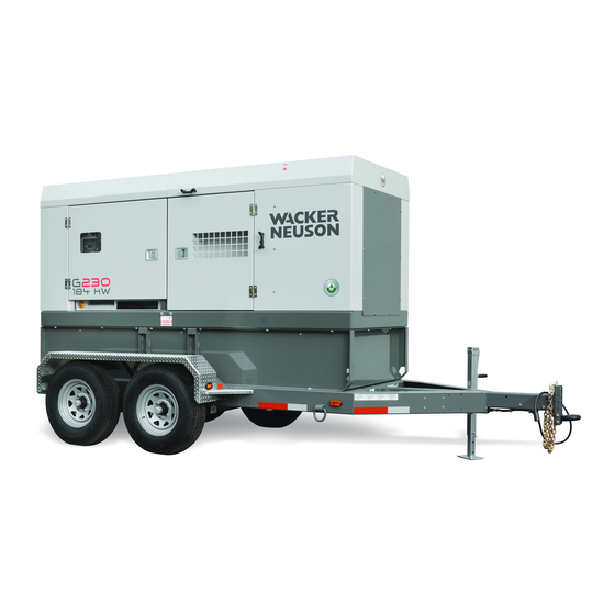
- Page 1 Operator’s Manual Mobile Generator G 230 G 240 5000186930 0215...
- Page 2 Copyright notice © Copyright 2015 by Wacker Neuson Production Americas LLC All rights, including copying and distribution rights, are reserved. This publication may be photocopied by the original purchaser of the machine. Any other type of reproduction is prohibited without express written permission from Wacker Neuson Production Americas LLC.
- Page 3 Machine Identification SAVE THESE INSTRUCTIONS—This manual contains important instructions for the machine models below. These instructions have been written expressly by Wacker Neuson Production Americas LLC and must be followed during installation, operation, and maintenance of the machines. Machine Item Number...
-
Page 4: Foreword
Use the separate Parts Book supplied with the machine to order replacement parts. If you are missing any of these documents, please contact Wacker Neuson to order a replacement or visit www.wackerneuson.com. When ordering parts or requesting service information, be prepared to provide ... - Page 5 Serious injury hazards to the operator and persons in the work area Permanent damage to the machine which will not be covered under warranty Contact your Wacker Neuson dealer immediately if you have questions about approved or unapproved parts, attachments, or modifications. wc_tx003565gb_FM10.fm...
- Page 6 Foreword Notes wc_tx003565gb_FM10.fm...
-
Page 7: Table Of Contents
G 230 / G 240 Table of Contents Foreword Safety Information Signal Words Used in this Manual ............. 13 Machine Description and Intended Use ..........14 Safety Guidelines for Operating the Machine ........15 Service Safety ..................17 Operator Safety while Using Internal Combustion Engines ....19 Safety Guidelines for Mobile Generators ........... - Page 8 Table of Contents G 230 / G 240 Operation (Basler Controller) Main Circuit Breaker ................54 Engine Start Switch ................55 Genset Pre-Alarms and Alarms (Shut-Down Conditions) ....56 Overcurrent Condition ................. 57 Idle Switch ..................57 Diesel Particulate Filter (DPF) ............58 Using the Lugs and the Convenience Receptacles ......
- Page 9 G 230 / G 240 Table of Contents Deep Sea Controller Buttons/Functions ........... 102 Genset Controller Alarms and Shut-Down Conditions ..... 104 Before Starting the Machine ............. 106 Starting and Running the Generator ..........107 Stopping the Generator ..............109 Emergency Stop Switch ..............
- Page 10 Table of Contents G 230 / G 240 14.4 Containment System ................ 148 14.5 Extended Run Tank (ERT) ............... 148 14.6 Engine Block Heater ................. 149 14.7 Automatic LCD Heat ................. 149 14.8 Low Coolant Shutdown ..............150 14.9 Temperature-Activated Shutters ............151 14.10...
- Page 11 24.1 Emission Control System Background Information ......213 24.2 Limited Defect Warranty for Exhaust Emission Control System ..214 24.3 Limited Defect Warranty for Wacker Neuson Emission Control Systems .................... 214 25 General Machine Schematics 25.1 Fuses ....................217 25.2 Trailer Wiring ..................
- Page 12 Electrical Schematic Components: G 230 / G 240 ......237 27.3 DC Schematic: G 240 John Deere Tier 3 ..........238 27.4 DC Schematic Components: G 240 John Deere Tier 3 ....239 27.5 DC Schematic: G 230 Cummins T4i ..........240 27.6 DC Schematic Components: G 230 Cummins T4i ......241 27.7...
-
Page 13: Safety Information
Mobile Generator Safety Information Safety Information Signal Words Used in this Manual This manual contains DANGER, WARNING, CAUTION, NOTICE, and NOTE signal words which must be followed to reduce the possibility of personal injury, damage to the equipment, or improper service. This is the safety alert symbol. -
Page 14: Machine Description And Intended Use
Mobile Generator Machine Description and Intended Use This machine is a mobile electric power source. The Wacker Neuson Mobile Generator consists of a trailer-mounted cabinet containing an electric alternator, a fuel tank, and a diesel engine. A control panel, receptacles, and connection lugs are provided on the side of the cabinet. -
Page 15: Safety Guidelines For Operating The Machine
To ensure safe operation of the machine: ■ Do not operate the machine if any safety devices or guards are missing or inoperative. ■ Do not modify or defeat the safety devices. ■ Only use accessories or attachments that are approved by Wacker Neuson. wc_tx003567gb_FM10.fm... - Page 16 Safety Information Mobile Generator Safe When operating this machine: operating ■ Remain aware of the machine’s moving parts. Keep hands, feet, and loose practices clothing away from the machine’s moving parts. When operating this machine: ■ Do not operate a machine in need of repair. ■...
-
Page 17: Service Safety
Machine When servicing or maintaining the machine: modifications ■ Use only accessories/attachments that are approved by Wacker Neuson. When servicing or maintaining the machine: ■ Do not defeat safety devices. ■ Do not modify the machine without the express written approval of Wacker Neuson. - Page 18 Safety Information Mobile Generator When cleaning the machine: ■ Do not clean the machine while it is running. ■ Never use gasoline or other types of fuels or flammable solvents to clean the machine. Fumes from fuels and solvents can become explosive. Personal Wear the following Personal Protective Equipment (PPE) while servicing or Protective...
-
Page 19: Operator Safety While Using Internal Combustion Engines
Mobile Generator Safety Information Operator Safety while Using Internal Combustion Engines WARNING Internal combustion engines present special hazards during operation and fueling. Failure to follow the warnings and safety standards could result in severe injury or death. ► Read and follow the warning instructions in the engine owner’s manual and the safety guidelines below. -
Page 20: Safety Guidelines For Mobile Generators
Safety Information Mobile Generator Safety Guidelines for Mobile Generators DANGER Carbon monoxide. Using a generator indoors CAN KILL YOU IN MINUTES. Generator exhaust contains carbon monoxide (CO). This is a poison you cannot see or smell. If you can smell the generator exhaust, you are breathing CO. But even if you cannot smell the exhaust, you could be breathing CO. - Page 21 Mobile Generator Safety Information General safety ■ Do not use evaporative starting fluids to start the engine. They are highly explosive. ■ Do not store items such as excess oil, rags, or tools on top of or inside the machine. These items are a fire hazard and can restrict cooling air. ■...
-
Page 22: Safety Guidelines For Towing The Machine
Safety Information Mobile Generator Safety Guidelines for Towing the Machine WARNING Risk of severe injury or death. Improper trailer condition and towing technique can lead to an accident. ► Obey the trailer manufacturer’s instructions and the instructions below to reduce the risk of an accident. -
Page 23: Safety Guidelines For Lifting The Machine
If you believe your trailer has a defect which could cause a crash or could cause injury or death, you should immediately inform the National Highway Traffic Safety Administration (NHTSA) in addition to notifying Wacker Neuson. If NHTSA receives similar complaints, it may open an investigation; and if it finds that a safety defect exists in a group of trailers, it may order a recall and remedy campaign. -
Page 24: Label Locations
Label Locations Mobile Generator Label Locations wc_gr011523 K XX DIESEL ULTRA LOW SULFUR SOLAMENTE COMBUSTIBLE DE FUEL ONLY ULTRABAJO CONTENIDO DE AZUFRE SEULEMENT CARBURANT DE SOUFRE ULTRA BAS 5200020535 DIESEL EXHAUST FLUID ONLY SEULEMENT FLUIDE O'ÉCHAPPEMENT DIESEL SÓLO LÍQUIDO DE ESCAPE DIESEL DIESEL... - Page 25 Mobile Generator Label Locations wc_gr009229 wc_tx003568gb_FM10.fm...
-
Page 26: Label Meanings
Label Meanings Mobile Generator Label Meanings WARNING WARNING WARNING Lock doors. Access can cause electric shock, arc flash, or injury. Read the Operator’s Manual for more information. Lock doors. Access can cause electric shock, arc flash or injury. Lock doors. Access can cause electric shock, arc flash or injury. ADVERTENCIA ADVERTENCIA Cierre las puertas. - Page 27 Mobile Generator Label Meanings DANGER Asphyxiation hazard. Do not run the machine DANGER indoors or in an enclosed area without adequate ventilation. Read the Operator’s PELIGRO DIESEL Manual for instructions. No sparks, flames, or STOP STOP DANGER burning objects near machine. Stop the engine 119050 119050 before adding fuel.
- Page 28 Label Meanings Mobile Generator WARNING WARNING WARNING Disconnect battery before servicing. ADVERTENCIA ADVERTENCIA Read the Operator’s Manual. AVERTISSEMENT AVERTISSEMENT 114891 114891 WARNING WARNING WARNING Generator can automatically start which can cause serious injury. Disconnect battery before servicing. Generator can automatically start Generator can automatically start which can cause serious injury.
- Page 29 2. Niveler la machine. 3. Bloquer les roues avec cales de roues. 3. Bloquer les roues avec cales de roues. ordered through Wacker Neuson or online at ordered through Wacker Neuson or online at 4. Mettre à terre la machine.
- Page 30 Label Meanings Mobile Generator WARNING WARNING / ADVERTENCIA / AVERTISSEMENT WARNING / ADVERTENCIA / AVERTISSEMENT Stop engine. Electrical hazard. Read STOP STOP Operator’s Manual. 178683 178683 Electrical ground 114886 114886 NOTICE Lifting point Operating the main circuit breaker supplies or interrupts power to the customer connection lugs.
- Page 31 Mobile Generator Label Meanings Engine wiring INTAKE HEATER 10AWG NOT USED ON SOME MODELS GROUND BAT - BAT+ FUEL RELAY FUEL LEVEL WHT/VIO SENDER COM 10AWG GROUND TO 2/0 AWG ENCLOSURE GROUND TO BOX STUD ENGINE BLOCK TOGGLE SWITCH GROUND TO ENCLOSURE BOX STUD 10AWG...
- Page 32 Label Meanings Mobile Generator Stop engine. STOP STOP 178682 178682 Remote start operation. Read Operator’s REMOTE START Manual for instructions. ARRANQUE REMOTO DEMARRAGE A DISTANCE 114897 NOTICE NOTICE NOTICE Receptacles not used when: Receptacles not used when: Receptacles not used when: Selector switch set to 208/120V and voltage greater than 228V.
- Page 33 Mobile Generator Label Meanings (on trailer, if equipped) Certification Label (VIN Number) Also attached to each unit is a Certification Label. This label specifies that the trailer conforms with all Federal Motor Vehicle Standards in effect at the time of manufacture. The label includes the Vehicle Identification Number (VIN) for the trailer.
- Page 34 Label Meanings Mobile Generator (if equipped) NOTICE Mobile generator must be level for proper operation of lube level maintainer. NOTICE NOTICE Mobile Generator must be level for proper Mobile Generator must be level for proper operation of lube level maintainer. operation of lube level maintainer.
- Page 35 Mobile Generator Label Meanings Notification of California emissions compliance Ultra low sulfur fuel only WARNING WARNING ADVERTENCIA ADVERTENCIA AVERTISSEMENT AVERTISSEMENT 5200005890 5200005890 WARNING Explosion hazard. ■ Do not use evaporative starting fluids such as ether on this engine. ■ The engine is equipped with a cold starting aid. Using evaporative starting fluids can cause an explosion which can cause engine damage, personal injury, or death.
-
Page 36: Lifting And Transporting
Lifting and Transporting Mobile Generator Lifting and Transporting Lifting the Machine ■ Lifting equipment (crane, hoist, or fork truck) capable of supporting the Requirements machine’s weight ■ Lifting devices (hooks, chains, and shackles) capable of supporting the machine’s weight ■ Engine stopped Lifting the A lifting eye is used for lifting the machine. -
Page 37: Before Towing Checklist
Mobile Generator Lifting and Transporting Before Towing Checklist Before towing the machine, check the licensing requirements for trailers in your area. Also check the following items: Towing vehicle Check that the towing vehicle is rated to tow the load. ... -
Page 38: Towing The Machine
Lifting and Transporting Mobile Generator Towing the Machine Background The generator’s trailer is equipped with brakes (surge or electric), safety chains (a), lights, and a coupler (pintle or ball-type) (b). wc_gr011430 Brakes Only use the brakes as designed. ■ The breakaway cable (c) is not a parking brake and should not be used as one. ■... -
Page 39: Preparing The Machine For Transport On A Truck Or Trailer
Mobile Generator Lifting and Transporting Preparing the Machine for Transport on a Truck or Trailer ■ Machine stopped Requirements ■ Flatbed truck or trailer capable of supporting the machine’s weight ■ Chains, hooks, or straps capable of supporting the machine’s weight WARNING Crushing hazard. -
Page 40: Hazardous Materials Placards
Lifting and Transporting Mobile Generator Hazardous Materials Placards Overview Hazardous materials placards may have been provided with your machine. Transport Canada, and the Canadian Transportation of Dangerous Goods Act, require that these hazardous materials placards be permanently applied to certain machines if they are to be transported or towed on Canadian roads. -
Page 41: Testing The Breakaway System (Hydraulic Surge Brakes)
Mobile Generator Lifting and Transporting Testing the Breakaway System (Hydraulic Surge Brakes) ■ Hydraulic reservoir filled Requirements ■ Machine parked on a flat surface When Test the breakaway system: ■ Before towing ■ After filling the hydraulic reservoir Procedure Perform the following procedure to test the breakaway system. 1. - Page 42 Lifting and Transporting Mobile Generator Continued from the previous page. 7. Stop the tow vehicle. 8. Release the brake by simultaneously pulling on the breakaway cord and prying the locking spring with a screwdriver (c) or pry bar. wc_gr008510 Result The procedure to test the breakaway system is now complete.
-
Page 43: Testing The Breakaway System (Electric Brakes)
Mobile Generator Lifting and Transporting Testing the Breakaway System (Electric Brakes) ■ Voltmeter Requirements ■ Battery charger or backup battery (charged) When Test the breakaway system: ■ Before towing ■ Monthly if the machine is not in service Procedure Perform the following procedure to test the breakaway system. NOTICE: Disconnect the trailer wiring plug from the tow vehicle before testing. - Page 44 Lifting and Transporting Mobile Generator Continued from the previous page. 5. If the brakes did not function, check the voltage of the breakaway battery. To do so: a. Remove the cover of the battery box. b. Remove the wires connected to the breakaway battery (d). c.
-
Page 45: Machine Setup
1. Make sure all loose packaging materials have been removed from the machine. 2. Check the machine and its components for damage. If there is visible damage, do not operate the machine! Contact your Wacker Neuson dealer immediately for assistance. -
Page 46: Positioning The Machine
► Do not operate the machine near flammable vapors, fuels, or combustibles. CO Alarms Because this machine produces carbon monoxide (CO), Wacker Neuson recommends that CO alarms be installed in all structures in close proximity to the machine. CO alarms provide an extra measure of protection against this poison that you cannot see or smell. - Page 47 Mobile Generator Machine Setup Continued from the previous page. Procedure Perform the following procedure to position the machine. 1. Place the machine on solid, stable, and level ground. wc_gr009186 2. For machines with trailers, install chocks (a) under the wheels. Result The machine is now properly positioned.
-
Page 48: Grounding The Generator
Machine Setup Mobile Generator Grounding the Generator External A ground connection is located at the customer connection terminal lugs. grounding wc_gr011524 This ground connection is used for electrically grounding the generator when necessary to comply with the National Electrical Code and other federal, state, and local regulations. -
Page 49: Recommended Fuel
Mobile Generator Machine Setup Recommended Fuel Low temperatures cause diesel fuel to gel. Always use the proper fuel for the conditions. Follow the guidelines in the table below. Lowest expected ambient Recommended fuel temperature Above freezing #2 diesel plus additives <... -
Page 50: Refueling The Machine (Basler Controller)
Machine Setup Mobile Generator Refueling the Machine (Basler Controller) ■ Machine shut down Requirements ■ Engine cool ■ Machine/fuel tank level with the ground ■ Remote switch disconnected from the remote run terminal ■ Fresh, clean fuel supply Procedure Perform the procedure below to refuel the machine. WARNING Fire hazard. -
Page 51: Refueling The Machine (Deep Sea Controller)
Mobile Generator Machine Setup Refueling the Machine (Deep Sea Controller) ■ Engine stopped Requirements ■ Machine/fuel tank level with the ground ■ Remote switch disconnected from the remote run terminal ■ Fresh, clean fuel supply Procedure Perform the procedure below to refuel the machine. WARNING Fire hazard. -
Page 52: Operation, Control, And Component Locations
Operation, Control, and Component Locations Operation, Control, and Component Locations Control / Component Locations Ø STOP DIAGNOSTICS DIAGNOSEN DIAGNOSTICOS DIAGNOSTICS START / RUN START / RUN START / LAUFEN START / LAUFEN ARRANQUE / MARCHA ARRANQUE / MARCHA DEMARRER / MARCHE DEMARRER / MARCHE APAGADO APAGADO... - Page 53 Operation, Control, and Component Locations wc_gr011534 Ref. Description Ref. Description Main circuit breaker GFI receptacle (120 VAC, 20 Amp) Voltage adjustment rheostat Remote run terminal block Hour meter Emergency stop switch (If equipped) Interlock switch (lug panel door switch) Diesel Particulate Filter (DPF) switch and indicator Manual conditioning switch for aftertreatment exhaust system...
-
Page 54: Main Circuit Breaker
Operation (Basler Controller) Main Circuit Breaker Location Various styles of main circuit breakers may be found on Wacker Neuson Mobile generators. The main circuit breaker (a) is located on the control panel. Note: Graphic is representative only. Your machine may vary. -
Page 55: Engine Start Switch
Mobile Generator Operation (Basler Controller) Engine Start Switch Description The engine start switch (a) is a three-position switch: “REMOTE START”, “OFF”, and “START/RUN”. APAGADO APAGADO ARRET ARRET REMOTE START REMOTE START START / RUN START / RUN START / LAUFEN START / LAUFEN FERNSTART FERNSTART... -
Page 56: Genset Pre-Alarms And Alarms (Shut-Down Conditions)
Operation (Basler Controller) Mobile Generator Genset Pre-Alarms and Alarms (Shut-Down Conditions) Background The genset controller monitors variables of engine and machine function. The genset controller is programmed to signal pre-alarm conditions, and to shut down the machine when an alarm condition exists. Pre-alarms Pre-alarm conditions are: ■... -
Page 57: Overcurrent Condition
Mobile Generator Operation (Basler Controller) Overcurrent Condition Along with engine functions, the genset controller continuously monitors the current load in each leg. The values for current overload are programmed into the ECM at the factory and are different for each generator size. Ø... -
Page 58: Diesel Particulate Filter (Dpf)
Operation (Basler Controller) Mobile Generator Diesel Particulate Filter (DPF) Overview The machine may be equipped with a Diesel Particulate Filter (DPF). The DPF (a) helps to protect the environment by removing soot from the engine exhaust. wc_gr010593 Function Sustained operation of the generator under load heats the DPF to a temperature high enough to burn accumulated soot. -
Page 59: Using The Lugs And The Convenience Receptacles
Mobile Generator Operation (Basler Controller) Using the Lugs and the Convenience Receptacles Overview Loads can be connected to the genset in two different ways: 1. At the connection lugs (r). Located as shown, behind the lug door, the connection lugs serve as connection points for cables. -
Page 60: Selecting The Voltage
Operation (Basler Controller) Mobile Generator Selecting the Voltage Background Selecting the voltage is a two-step process. First, select the voltage using the voltage selector. Then, use the voltage adjustment rheostat to fine-tune the voltage to your exact requirements. Location The voltage selector (a) is located behind the access door in the upper half of the control box. - Page 61 Mobile Generator Operation (Basler Controller) Continued from the previous page. Description The voltage selector mechanically changes the connections between the generator output leads and the terminal lugs on the generator. = 40Nm (29.5 Ft Lbs) L1-N = 120V L1-N = 277V L2-N = 120V L2-N = 277V L3-N = 120V...
- Page 62 Operation (Basler Controller) Mobile Generator Continued from the previous page. Using the The voltage adjustment rheostat (d) is used to fine-tune the voltage as needed rheostat while the machine is running. wc_gr010391 Care must be taken when using the voltage adjustment rheostat because adjusting the voltage for 3-phase operation affects the voltage available at the single-phase outlets.
-
Page 63: Before Starting The Machine
Mobile Generator Operation (Basler Controller) Before Starting the Machine WARNING Personal injury hazard. Failure to follow the listed procedures may cause injury to personnel or damage to the generator. ► Make sure that all persons setting up the generator are certified or fully trained on the installation of the generator. -
Page 64: Starting And Running The Generator
Operation (Basler Controller) Mobile Generator 7.10 Starting and Running the Generator CAUTION Possibility of injury or equipment damage. Failure to match phase, voltage, and frequency may cause equipment connected to the generator to operate incorrectly. ► When using the generator as a stand-by or substitute power supply, make sure the phase, voltage, and frequency of the generator matches that of the utility lines or of any other power source normally used. - Page 65 LCD panel displays EMERGENCY STOP, and the pre-alarm/alarm LED illuminates. If the LCD does not display EMERGENCY STOP, do not continue. Contact a Wacker Neuson dealer for assistance. Pull out the emergency stop button after verifying the display. c. Set the engine start switch to OFF.
-
Page 66: Stopping The Machine
Operation (Basler Controller) Mobile Generator 7.11 Stopping the Machine Check with other personnel on the jobsite and let them know that power is being turned off. Make sure that the power shutdown will not create any hazards by turning off devices such as pumps, heaters, or lights that may need to be kept on. 1. -
Page 67: Lcd Panel: Monitoring Machine Operation
Mobile Generator Operation (Basler Controller) 7.13 LCD Panel: Monitoring Machine Operation Overview Generator and engine information is continuously monitored and displayed on the LCD panel. The upper line displays generator information. The lower line displays engine information. Generator Engine wc_gr010202 Generator The upper line of the LCD panel shows the voltage, phase, amperage, and information... - Page 68 Operation (Basler Controller) Mobile Generator Continued from the previous page. Engine The lower line of the LCD panel shows fuel level, temperature, oil pressure, and information battery voltage. The information is shown when the engine start switch is set to RUN/START.
-
Page 69: Working With Basler Controller
Mobile Generator Working with Basler Controller Working with Basler Controller How to Use the Genset Controller LCD and Keypad Basics The LCD (a) is used to display information regarding machine performance and operating status. The keypad (b) is used to maneuver through the various menus of the genset controller. -
Page 70: Menu Diagram Of The Genset Controller
Working with Basler Controller Mobile Generator Menu Diagram of the Genset Controller The various menus of the genset controller are divided into two main categories: METERING and SETTINGS. Access to the METERING menu and to the SETTINGS menu is done through the MAIN MENU. To access the MAIN MENU from either the monitoring screen or the READY screen, press the right arrow button. -
Page 71: Menu Diagram Components
Mobile Generator Working with Basler Controller Menu Diagram Components Menu Item Description Menu Item Description Alarm Config J1939 Active DTC Alarm configuration Diagnostic Trouble Codes Alarm Configuration J1939 Data — — Alarms J1939 Engine Config — Engine configuration Alarm–Status J1939 Previous DTC —... -
Page 72: Using The Metering And Settings Menus
Working with Basler Controller Mobile Generator Menu Item Description Menu Item Description Generator — — Generator Protection Voltages — — Hrs to Maintenance — Hours to maintenance — Inputs — — — Using the Metering and Settings Menus Background The various menus of the genset controller are divided into two main categories: METERING, and SETTINGS. -
Page 73: Logging In To The Genset Controller By Entering The Password
Mobile Generator Working with Basler Controller Logging in to the Genset Controller by Entering the Password Precaution Only change parameters when the READY screen is displayed (start switch in the REMOTE START position). Password In order to change the parameters under the settings menu, you must be “logged in”... - Page 74 Working with Basler Controller Mobile Generator Continued from the previous page. 3. Using the up/down arrow buttons, scroll through the setting parameters until ENTER PASSWORD is highlighted. Then, press the check mark button (5). 4. The password entry screen appears with a letter “A” as the default character. Use the up/down arrow buttons to change the “A”...
- Page 75 Mobile Generator Working with Basler Controller At the To log in when prompted to enter the password, do the following: PASSWORD 1. The password entry screen appears with a letter “A” as the default character. prompt Use the up/down arrow buttons to change the “A” to “O”. Then, press the right arrow button to move the cursor to the next position.
-
Page 76: Adjusting The Lcd Screen Contrast
Working with Basler Controller Mobile Generator Adjusting the LCD Screen Contrast Requirements Machine stopped Start switch in REMOTE START Note: Internal programming of the genset controller, or closed connections to a remote start switch, may cause the machine to start unexpectedly. Be prepared for the engine to start even with the engine start switch in the REMOTE START position. -
Page 77: Changing The Time/Date Settings
Mobile Generator Working with Basler Controller Changing the Time/Date Settings Requirements Machine stopped Start switch in REMOTE START Note: Internal programming of the genset controller, or closed connections to a remote start switch, may cause the machine to start unexpectedly. Be prepared for the engine to start even with the engine start switch in the REMOTE START position. -
Page 78: Changing The Sender Fail Time Delays
Working with Basler Controller Mobile Generator Changing the Sender Fail Time Delays Requirements Machine stopped Start switch in REMOTE START Note: Internal programming of the genset controller or connections to a remote start switch may cause the machine to start unexpectedly. Be prepared for the engine to start even with the engine start switch in the REMOTE START position. - Page 79 Mobile Generator Working with Basler Controller Continued from the previous page. 2. Using the up/down arrow buttons (2, 3) highlight SETTINGS. Then, press the right arrow button. 3. Highlight ALARM CONFIGURATION. Then, press the right arrow button. 4. Highlight SENDER FAIL. Then, press the right arrow button. 5.
-
Page 80: Changing The Units Of Measure
Working with Basler Controller Mobile Generator Changing the Units of Measure Requirements Machine stopped Start switch in REMOTE START Note: Internal programming of the genset controller, or closed connections to a remote start switch, may cause the machine to start unexpectedly. Be prepared for the engine to start even with the engine start switch in the REMOTE START position. - Page 81 Mobile Generator Working with Basler Controller Continued from the previous page. 8. Exit by pressing the left arrow button (4) twice or until the LCD displays the SETTINGS menu. Then, scroll to LOGOUT and press the check mark button. Press the left arrow button so that the READY screen appears. Result The units of measure have now been changed.
-
Page 82: Changing The Low Fuel Pre-Alarm Setting
Working with Basler Controller Mobile Generator 8.10 Changing the Low Fuel Pre-Alarm Setting Requirements Machine stopped Start switch in REMOTE START Note: Internal programming of the genset controller, or closed connections to a remote start switch, may cause the machine to start unexpectedly. Be prepared for the engine to start even with the engine start switch in the REMOTE START position. - Page 83 Mobile Generator Working with Basler Controller Continued from the previous page. 8. Using the up/down arrow buttons, change the value as desired. Press the check mark button when finished. 9. Exit by pressing the left arrow button (4) three times or until the LCD displays the SETTINGS menu.
-
Page 84: Changing Or Disabling The Low Fuel Alarm Setting
7.44 G 150 8.85 G 180 10.8 G 240 13.5 Procedure Perform the procedure below to change the low fuel alarm setting. 1. Press the right arrow button (1) to access the MAIN MENU. This procedure continues on the next page. - Page 85 Mobile Generator Working with Basler Controller Continued from the previous page. 2. Using the up/down arrow buttons (2, 3) highlight SETTINGS. Then, press the right arrow button.Highlight ALARM CONFIG. Then, press the right arrow button. 3. Highlight ALARMS. Then, press the right arrow button. 4.
-
Page 86: Changing The Cooldown Time Setting
Working with Basler Controller Mobile Generator 8.12 Changing the Cooldown Time Setting Requirements Machine stopped Start switch in REMOTE START Note: Internal programming of the genset controller, or closed connections to a remote start switch, may cause the machine to start unexpectedly. Be prepared for the engine to start even with the engine start switch in the REMOTE START position. - Page 87 Mobile Generator Working with Basler Controller Continued from the previous page. 4. Highlight CRANK SETTINGS. Then, press the right arrow button. 5. Highlight COOLDOWN TIME. Then, press the check mark button (5). 6. If you are not logged in, enter the password “OP”. Press the check mark button. 7.
-
Page 88: Changing The Pre-Crank Time Delay (Glow Plug Timer)
Working with Basler Controller Mobile Generator 8.13 Changing the Pre-Crank Time Delay (Glow Plug Timer) Requirements Machine stopped Start switch in REMOTE START Note: Internal programming of the genset controller, or closed connections to a remote start switch, may cause the machine to start unexpectedly. Be prepared for the engine to start even with the engine start switch in the REMOTE START position. - Page 89 Mobile Generator Working with Basler Controller Continued from the previous page. 4. Highlight CRANK SETTINGS. Then, press the right arrow button. 5. Highlight PRECRANK DELY. Then, press the check mark button (5). 6. If you are not logged in, enter the password “OP”. Press the check mark button. 7.
-
Page 90: Changing The Maintenance Interval
Working with Basler Controller Mobile Generator 8.14 Changing the Maintenance Interval Requirements Machine stopped Start switch in REMOTE START Note: Internal programming of the genset controller, or closed connections to a remote start switch, may cause the machine to start unexpectedly. Be prepared for the engine to start even with the engine start switch in the REMOTE START position. - Page 91 Mobile Generator Working with Basler Controller Continued from the previous page. 3. Highlight ALARM CONFIGURATION. Then, press the right arrow button. 4. Highlight PRE-ALARMS. Then, press the right arrow button. 5. Highlight the MAINTENANCE INTERVAL. Then, press the right arrow button. 6.
-
Page 92: Resetting The Maintenance Interval Pre-Alarm
Working with Basler Controller Mobile Generator 8.15 Resetting the Maintenance Interval Pre-Alarm Requirements Machine stopped Start switch in REMOTE START Note: Internal programming of the genset controller, or closed connections to a remote start switch, may cause the machine to start unexpectedly. Be prepared for the engine to start even with the engine start switch in the REMOTE START position. - Page 93 Mobile Generator Working with Basler Controller Continued from the previous page. 3. With the PRE-ALARMS screen showing (MAINT INTERVAL highlighted), press the left arrow button (4) three times. 4. Using the up/down arrow buttons highlight METERING. Then, press the right arrow button.
-
Page 94: Resetting A Loss Of Voltage Pre-Alarm
Working with Basler Controller Mobile Generator 8.16 Resetting a Loss of Voltage Pre-Alarm Background The loss of voltage pre-alarm condition occurs most often because of an open lug door switch. During a loss of voltage pre-alarm, the LCD will display the screens below. -
Page 95: Accessing And Using The Event Log
Mobile Generator Working with Basler Controller 8.17 Accessing and Using the Event Log Requirements Machine stopped Start switch in REMOTE START Note: Internal programming of the genset controller, or closed connections to a remote start switch, may cause the machine to start unexpectedly. Be prepared for the engine to start even with the engine start switch in the REMOTE START position. - Page 96 Working with Basler Controller Mobile Generator LCD Screen Meaning GEN TEST LOADED Generator test loaded MAINT INTERVAL P Maintenance interval pre-alarm LOW COOL LEVEL A Low coolant level alarm 5. Highlight the event of interest. Then, press the right arrow button. Details of the event appear: They are: ACTIVE ...
-
Page 97: Operation (Deep Sea Controller)
Operation (Deep Sea Controller) Main Circuit Breaker Location Various styles of main circuit breakers may be found on Wacker Neuson Mobile generators. The main circuit breaker (a) is located on the control panel. Note: Graphic is representative only. Your machine may vary. -
Page 98: Genset Controller Power Switch
Operation (Deep Sea Controller) Mobile Generator Genset Controller Power Switch Description The genset controller power switch (a) is a two-position switch: ON and OFF. DSE 7310 STOP wc_gr011478 Function Position Function LCD Screen When set to this position: “Generator at Rest” followed ■... -
Page 99: Selecting The Voltage
Mobile Generator Operation (Deep Sea Controller) Selecting the Voltage Background Selecting the voltage is a two-step process. First, select the voltage using the voltage selector. Then, use the voltage adjustment rheostat to fine-tune the voltage to your exact requirements. Location The voltage selector (a) is located behind the access door in the upper half of the control box. - Page 100 Operation (Deep Sea Controller) Mobile Generator Continued from the previous page. Description The voltage selector mechanically changes the connections between the generator output leads and the terminal lugs on the generator. = 40Nm (29.5 Ft Lbs) L1-N = 120V L1-N = 277V L2-N = 120V L2-N = 277V L3-N = 120V...
- Page 101 Mobile Generator Operation (Deep Sea Controller) Continued from the previous page. Using the The voltage adjustment rheostat (d) is used to fine-tune the voltage as needed rheostat while the machine is running. wc_gr010391 Care must be taken when using the voltage adjustment rheostat because adjusting the voltage for 3-phase operation affects the voltage available at the single-phase outlets.
-
Page 102: Deep Sea Controller Buttons/Functions
Operation (Deep Sea Controller) Mobile Generator Deep Sea Controller Buttons/Functions DEEP SEA ELECTRONIC DEEP SEA ELECTRONICS S DSE 731 DSE 7310 0 STOP Open Open Open Open Load Load Gen-Set Gen-Set Close Close Close Close AUTO O Stop/Reset Stop/Reset Manual Manual Lamp Lamp Test... - Page 103 Mobile Generator Operation (Deep Sea Controller) Ref. Button/function Stop / Reset Pressing this button: ■ Sets the genset controller into its Stop/Reset mode ■ Clears any alarm conditions for which the triggering criteria have been recti- fied. Manual mode Pressing this button: ■...
-
Page 104: Genset Controller Alarms And Shut-Down Conditions
Operation (Deep Sea Controller) Mobile Generator Genset Controller Alarms and Shut-Down Conditions Background The genset controller monitors variables of engine and machine function. The genset controller has two types of alarms: warning alarms and shut-down alarms. The genset controller also monitors for electrical trip conditions. Warning Warnings are non-critical alarm alarms... - Page 105 Mobile Generator Operation (Deep Sea Controller) Electrical trips Electrical trips are latching type alarms that stop the engine. During an electrical trip, the LEDs (6, 8) DEEP SEA ELECTRONICS illuminate, an audible alarm sounds, and DSE 7310 the machine is shut down. STOP Press the “Horn Reset”...
-
Page 106: Before Starting The Machine
Operation (Deep Sea Controller) Mobile Generator Before Starting the Machine WARNING Personal injury hazard. Failure to follow the listed procedures may cause injury to personnel or damage to the generator. ► Make sure that all persons setting up the generator are certified or fully trained on the installation of the generator. -
Page 107: Starting And Running The Generator
Mobile Generator Operation (Deep Sea Controller) Starting and Running the Generator CAUTION Possibility of injury or equipment damage. Failure to match phase, voltage, and frequency may cause equipment connected to the generator to operate incorrectly. ► When using the generator as a stand-by or substitute power supply, make sure the phase, voltage, and frequency of the generator matches that of the utility lines or of any other power source normally used. - Page 108 Operation (Deep Sea Controller) Mobile Generator Continued from the previous page. 7. The engine will crank. During a normal cycle, the engine cranks for 12 seconds and rests for 12 seconds. This cycle will repeat three times. Note: If the engine does not start within the normal cycle, the genset controller will shut down the engine.
-
Page 109: Stopping The Generator
Mobile Generator Operation (Deep Sea Controller) Stopping the Generator Requirements Before stopping the generator: ■ Check with other personnel on the jobsite and let them know that power is being turned off. ■ Make sure that the power shutdown will not create any hazards by turning off devices such as pumps, heaters, or lights that may need to be kept on. -
Page 110: Emergency Stop Switch
Operation (Deep Sea Controller) Mobile Generator Emergency Stop Switch Location The emergency stop switch is the red button (a) located to the left of the control panel. The button can be accessed with the panel doors closed. It is electrically isolated from the switch and also from the rest of the metering panel. -
Page 111: Engine And Generator Monitoring
Mobile Generator Operation (Deep Sea Controller) 9.10 Engine and Generator Monitoring Description Engine and generator information is displayed on the LCD panel and scrolls continuously while the generator is operating. For more information on the Deep Sea controller, see chapter Working with the Deep Sea Controller. -
Page 112: Working With Deep Sea Controller: Dse 7310
Working with Deep Sea Controller: DSE 7310 10 Working with Deep Sea Controller: DSE 7310 10.1 Introduction During normal operation, the genset controller displays current information on machine performance and operating status. The keypad (e) provides access to additional monitoring functions through a series of menus displayed on the LCD panel (f). -
Page 113: Navigating The Menus
Working with Deep Sea Controller: DSE 7310 10.2 Navigating the Menus The graphic below serves as a navigational aid when accessing the various menus of the genset controller. See the accompanying table for information about the menu items. MENU NAVIGATION MENU NAVIGATION Status Status... - Page 114 Working with Deep Sea Controller: DSE 7310 Menu Item Description Menu Item Description About — Module Information — Active Config Generator Configuration Gen Load (h) Generator Load kVArh Alarms Gen Load (%) Generator Load Percent Alarms Active — Gen Load (kVA) Generator Load kVA —...
-
Page 115: Adjusting Screen Contrast
Working with Deep Sea Controller: DSE 7310 10.3 Adjusting Screen Contrast Overview The contrast of the LCD display can be adjusted to suit the operator’s preference. Procedure Perform the procedure below to adjust the screen contrast. 1. Access the “Editor—Display” menu on the LCD panel (f) by pressing and holding the check mark button (5) on the keypad. -
Page 116: How To Reset The Maintenance Timer
Working with Deep Sea Controller: DSE 7310 10.4 How to Reset the Maintenance Timer Background The maintenance timer is preset to 500 hours. When the maintenance timer times out, the genset controller sounds the audible alarm. Procedure Perform the procedure below to reset the maintenance timer. 1. -
Page 117: How To Connect Loads
Mobile Generator How to Connect Loads 11 How to Connect Loads 11.1 Lug Terminal Connection Diagrams For machines with capabilities up to 480V High Wye 240V Low Wye 139V 139V 240V 139V 240V 240V 240V wc_gr011542 wc_tx003620gb_FM10.fm... -
Page 118: Best Practices For Balancing Loads
How to Connect Loads Mobile Generator 11.2 Best Practices for Balancing Loads WARNING Electric shock hazard. High voltage can cause serious injury or death. ► Connections must be made by a qualified electrician. Background Three-phase (3Ø) loads are, by their nature, balanced. It is when single-phase (1Ø) loads are combined with existing 3Ø... - Page 119 Mobile Generator How to Connect Loads Continued from the previous page. L1 L2 L3 N GND With voltage selected to 240 HOT HOT When connecting multiple 120V 1Ø loads: Use L1 as "hot" for first load. Use L3 as "hot" for second load. Use L2 as "hot"...
-
Page 120: Connecting 480V, 3-Phase And Single-Phase Loads
How to Connect Loads Mobile Generator 11.3 Connecting 480V, 3-Phase and Single-Phase Loads WARNING Electric shock hazard. High voltage can cause serious injury or death. ► Connections must be made by a qualified electrician. 1. Stop the engine and turn the main circuit breaker off. 2. -
Page 121: Connecting A 240V 3Ø Load And A 240V 1Ø Load
Mobile Generator How to Connect Loads 11.4 Connecting a 240V 3Ø Load and a 240V 1Ø Load WARNING Electric shock hazard. High voltage can cause serious injury or death. ► Connections must be made by a qualified electrician. 1. Stop the engine and turn the main circuit breaker off. 2. -
Page 122: Connecting A 220-240V 3Ø Load And Multiple 127-133V 1Ø Loads
How to Connect Loads Mobile Generator 11.5 Connecting a 220–240V 3Ø Load and Multiple 127–133V 1Ø Loads WARNING Electric shock hazard. High voltage can cause serious injury or death. ► Connections must be made by a qualified electrician. 1. Stop the engine and turn the main circuit breaker off. 2. -
Page 123: Connecting A 208V 3Ø Load And Multiple 120V 1Ø Loads
Mobile Generator How to Connect Loads 11.6 Connecting a 208V 3Ø Load and Multiple 120V 1Ø Loads WARNING Electric shock hazard. High voltage can cause serious injury or death. ► Connections must be made by a qualified electrician. 1. Stop the engine and turn the main circuit breaker off. 2. -
Page 124: Using Remote Start Capabilities
Using Remote Start Capabilities Mobile Generator 12 Using Remote Start Capabilities 12.1 Remote Run Terminal Block Location The remote run terminal block (a) is located as shown. Note: Graphic is representative only. Your machine may vary. Ø DIAGNOSTICS DIAGNOSEN DIAGNOSTICOS DIAGNOSTICS 4,000 ft 1,219 m... -
Page 125: Remote Transfer Switch
Mobile Generator Using Remote Start Capabilities 12.2 Remote Transfer Switch Background A remote transfer switch is designed to transfer electrical loads from the normal power source (utility) to the emergency power source (generator) when normal voltage falls below a prescribed level. The remote transfer switch automatically returns the load back to the normal source when power is restored back to operating levels. -
Page 126: Preparing For Automatic/Remote Start-Up (Basler)
Using Remote Start Capabilities Mobile Generator 12.3 Preparing for Automatic/Remote Start-Up (Basler) Background When the engine start switch is in the REMOTE START position, the generator can be started remotely through a automatic transfer switch or other type of remote start switch. -
Page 127: Preparing For Automatic/Remote Start-Up (Deep Sea)
Mobile Generator Using Remote Start Capabilities 12.4 Preparing for Automatic/Remote Start-Up (Deep Sea) Background In AUTO mode, the generator can be started remotely, either through a transfer switch or some other type of remote start switch. AUTO mode is the normal setting when using the generator as a stand-by power supply. - Page 128 Using Remote Start Capabilities Mobile Generator Continued from the previous page. 2. Leave the genset controller power switch in the ON position. 3. Close the main circuit breaker. 4. Press the AUTO mode button. 5. Secure the generator by closing and locking all doors. The generator is now ready for automatic starting.
-
Page 129: Diagnostic Trouble Codes (Dtc)
Mobile Generator Diagnostic Trouble Codes (DTC) 13 Diagnostic Trouble Codes (DTC) 13.1 Accessing DTCs with the Basler Controller Background This machine may include an engine that has self-diagnostic capabilities. These engines communicate issues with the engine through Diagnostic Trouble Codes (DTCs). -
Page 130: Accessing Engine Dtcs Using The Deep Sea Controller
Diagnostic Trouble Codes (DTC) Mobile Generator 13.2 Accessing Engine DTCs using the Deep Sea Controller Background This machine may include an engine that has self-diagnostic capabilities. These engines communicate issues with the engine through Diagnostic Trouble Codes (DTCs). When a DTC is present, an alert will show on the LCD panel display. A DTC is a two part code consisting of a Suspect Parameter Number (SPN), and a Failure Mode Identifier (FMI). -
Page 131: List Of Engine Diagnostic Trouble Codes (Dtcs)
Mobile Generator Diagnostic Trouble Codes (DTC) 13.3 List of Engine Diagnostic Trouble Codes (DTCs) Failure Code String Displayed Description — DATA HI MOST SEVERE Data is higher than expected at the most severe level — DATA LO MOST SEVERE Data is lower than expected at the most severe level —... - Page 132 Diagnostic Trouble Codes (DTC) Mobile Generator Failure Code String Displayed Description Thr Pos Sns Volt HI Throttle Position Sensor Input Voltage (High) Thr Pos Sns Volt LO Throttle Position Sensor Input Voltage (Low) Thr Pos Sns Volt OOR Throttle Voltage (Out of Range) FUEL DELIV PRS LO LO Engine Fuel Delivery Pressure is below the LOW LOW...
- Page 133 Mobile Generator Diagnostic Trouble Codes (DTC) Failure Code String Displayed Description EGR Mixed Air Tmp HI Exhaust Gas Recirculation Mixed Air High (Least Severe) EGR Air Temp Vlt HI Exhaust Gas Recirculation Mixed Air Temp Volt- age (High) EGR Air Temp Vlt LO Exhaust Gas Recirculation Mixed Air Temp Volt- age (Low) EGR Mixed Air Tmp HI...
- Page 134 Diagnostic Trouble Codes (DTC) Mobile Generator Failure Code String Displayed Description KSW BATT VOLTS HI HI Key Switch Battery Potential is above the HIGH HIGH threshold KSW BATT VOLTS LO LO Key Switch Battery Potential is below the LOW LOW threshold KSW BATT VOLTS HI Key Switch Battery Potential is above the HIGH threshold...
- Page 135 Mobile Generator Diagnostic Trouble Codes (DTC) Failure Code String Displayed Description ABS ACTIVE Caption String for Antilock Brake System (ABS) active Inj Short to PWR Injector Wiring Shorted to Power Inj Short to GND Injector Wiring Shorted to Ground DIAGNOSTIC LAMP Caption String for Diagnostic Lamp Inj Spply Vlt Problm Injector Supply Voltage Problem...
- Page 136 Diagnostic Trouble Codes (DTC) Mobile Generator Failure Code String Displayed Description CYLINDER 1 INJECTOR Caption String for Cylinder 1 Injector Cyl 2 EUI PN INVLD Cylinder #2 EUI Part Number (Invalid) Cyl 2 EUI Ckt OPEN Cylinder #2 EUI Circuit (Open) Cyl 2 EUI Ckt SHORT Cylinder #2 EUI Circuit (Shorted) Cyl 2 EUI Ckt MECH FL...
- Page 137 Mobile Generator Diagnostic Trouble Codes (DTC) Failure Code String Displayed Description CYLINDER 7 INJECTOR Caption String for Cylinder 7 Injector CYLINDER 8 INJECTOR Caption String for Cylinder 8 Injector CYLINDER 9 INJECTOR Caption String for Cylinder 9 Injector CYLINDER 10 INJECTOR Caption String for Cylinder 10 Injector CYLINDER 11 INJECTOR Caption String for Cylinder 11 Injector...
- Page 138 Diagnostic Trouble Codes (DTC) Mobile Generator Failure Code String Displayed Description AUX I/O 12 Caption String for Auxiliary I/O 12 AUX I/O 13 Caption String for Auxiliary I/O 13 AUX I/O 14 Caption String for Auxiliary I/O 14 AUX I/O 15 Caption String for Auxiliary I/O 15 AUX I/O 16 Caption String for Auxiliary I/O 16...
- Page 139 Mobile Generator Diagnostic Trouble Codes (DTC) Failure Code String Displayed Description 1172 Trbo Cmp Tmp Volt HI Turbo Compressor Inlet Temp Input Voltage (High) 1172 Trbo Cmp Tmp Volt LO Turbo Compressor Inlet Temp Input Voltage (Low) 1172 Trbo Cmp In Tmp MHI Turbo Compressor Inlet Temp (Moderately High) 1180 Trbo Trbn Tmp EXT HI...
- Page 140 Diagnostic Trouble Codes (DTC) Mobile Generator Failure Code String Displayed Description 1335 MISFIRE CYLINDER 13 Caption String for Misfire detected on a single engine cylinder 1336 MISFIRE CYLINDER 14 Caption String for Misfire detected on a single engine cylinder 1337 MISFIRE CYLINDER 15 Caption String for Misfire detected on a single engine cylinder...
- Page 141 Mobile Generator Diagnostic Trouble Codes (DTC) Failure Code String Displayed Description 2071 Tr Oil Can Msg NT RCV Trans. Oil, Tier Size, Vehicle Speed CAN Mes- sage Not Received 2629 TRBO 1 OUT TMP HI HI Turbocharger 1 outlet pressure is above the HIGH HIGH threshold 2629...
- Page 142 Diagnostic Trouble Codes (DTC) Mobile Generator Failure Code String Displayed Description 3719 DPF SOOT LVL EXT HI String for Diagnostic Trouble Code Indicating Diesel Particulate Filter Soot Level High - Most Severe Level 3719 DPF SOOT LVL HI String for Diagnostic Trouble Code Indicating Diesel Particulate Filter Soot Level High - Least Severe Level 3719...
- Page 143 Mobile Generator Diagnostic Trouble Codes (DTC) Failure Code String Displayed Description 523470 RAIL PRESSURE LMT VLV Caption String for Rail Pressure Limit Valve 523490 ECU ERROR String for Diagnostic Trouble Code Indicating ECU Error 523500 CAN MSG TIMEOUT Caption String indicating Can Message Timeout has occurred 523550 ECU ERROR...
- Page 144 Diagnostic Trouble Codes (DTC) Mobile Generator Failure Code String Displayed Description 523612 ECU ERROR String for Diagnostic Trouble Code Indicating ECU Error 523613 RAIL PRESSURE Caption String for Rail Pressure 523615 METERING UNIT VALVE Caption String for Metering Unit Valve 523617 ECU ERROR String for Diagnostic Trouble Code Indicating...
-
Page 145: Factory-Installed Options
This machine may be equipped with one or more of the following factory-installed options. To verify if any of these options are installed on your machine, contact Wacker Neuson Corporation at 1-800-770-0957. A nameplate listing the Model Number, Item Number, Revision, and Serial Number is attached to each unit. -
Page 146: Lockable Battery Disconnect
Factory-Installed Options Mobile Generator 14.2 Lockable Battery Disconnect A lockable ON/OFF switch is available which disconnects the battery. A padlock (not included) securely locks the switch in the OFF position. If equipped, the battery disconnect switch is mounted to the upper skid beneath the access door on either the right or left side of the machine. -
Page 147: Camlocks
Mobile Generator Factory-Installed Options 14.3 Camlocks A second optional outlet panel features camlock connectors for easy tool changes. Each connector is protected by a spring-loaded cover. NOTICE: Separate overcurrent protection must be provided. Do not exceed 400 amps per receptacle. WARNING Electric shock hazard. -
Page 148: Containment System
Factory-Installed Options Mobile Generator 14.4 Containment System Overspills and leaks are captured in the containment system (a). The containment system holds over 110% of the fluid contained in the machine. wc_gr002647 14.5 Extended Run Tank (ERT) An extended run (fuel) tank provides extended run time under a continuous full load. -
Page 149: Engine Block Heater
Mobile Generator Factory-Installed Options 14.6 Engine Block Heater The engine block heater option includes a block heater (a) with a cord (b). The function of the block heater is to heat the engine coolant/engine block to improve cold-weather engine starting. Plug the cord into a 120V power supply. 14.7 Automatic LCD Heat To improve the performance of the LCD panel in cold weather, the LCD panel... -
Page 150: Low Coolant Shutdown
Factory-Installed Options Mobile Generator 14.8 Low Coolant Shutdown Description The low-coolant shutdown system consists of an electronic sensor that monitors coolant level. The sensor (a) is mounted to the radiator and wired into the ECM. The sensor probe (b) is submerged in radiator coolant. Function If the probe senses no coolant, it sends a signal to the ECM. -
Page 151: Temperature-Activated Shutters
Mobile Generator Factory-Installed Options 14.9 Temperature-Activated Shutters The shutters (a) are mounted to the top of the generator enclosure. The shutters are designed to keep the engine compartment warm, thus increasing engine temperature during cold weather operation. The shutters are activated through a wax-pellet actuator (b) that is connected to the generator's cooling system. -
Page 152: Positive Air Shutoff Valve
Factory-Installed Options Mobile Generator 14.10 Positive Air Shutoff Valve Description Diesel engines may occasionally continue to run even after the machine has been turned off. This “runaway” condition occurs when combustible intake air is drawn into the engine. Pressing the emergency stop switch alone will not stop a runaway engine. -
Page 153: Quick-Disconnect Fuel Fittings
Mobile Generator Factory-Installed Options 14.11 Quick-Disconnect Fuel Fittings Quick-disconnect fuel fittings allow an external fuel supply to be connected to the engine. ■ Engine stopped and cool to the touch Requirements ■ Fuel supply and return hoses with compatible quick-disconnect fittings Note: Required fitting size is ISO 7241-1-Series B (3/8 in.) Procedure Perform the following procedure to connect the external fuel supply. -
Page 154: Lube Level Maintainer
Factory-Installed Options Mobile Generator 14.12 Lube Level Maintainer Description The lube level maintainer system protects the engine from low oil levels by providing an additional 6-quart oil reservoir. Oil from the reservoir is gravity-fed from the oil reservoir (a) through the control valve (b) and into the engine oil pan as needed. -
Page 155: Machines With Aftertreatment Exhaust System
15 Machines with Aftertreatment Exhaust System 15.1 How the Aftertreatment Exhaust System Works Background Many Wacker Neuson Generators with Tier 4 engines use an aftertreatment exhaust system to reduce emissions. There are five main components to the system: ■ Heat ■... -
Page 156: Filling The Def Tank
Machines with Aftertreatment Exhaust System 15.2 Filling the DEF Tank ■ Machine level with the ground Requirements ■ Remote switch disconnected from the remote run terminal ■ Fresh Diesel Exhaust Fluid (DEF)—also known as Aqueous Urea Solution 32% (AUS32)—manufactured to the standards of ISO 22241. Background The DEF refilling interface on this machine meets ISO 22241-4. - Page 157 Machines with Aftertreatment Exhaust System Continued from the previous page. 2. Set the engine start switch (a) to the REMOTE START position. The DEF level (in percentage of the DEF tank capacity) is displayed on the left side of the LCD screen.
-
Page 158: Shelf Life Of Diesel Exhaust Fluid (Def)
Machines with Aftertreatment Exhaust System 15.3 Shelf Life of Diesel Exhaust Fluid (DEF) The shelf life of DEF is a function of temperature and the amount of exposure to sunlight. Certain conditions can degrade the solution to a point where it will no longer meet the standards. -
Page 159: Monitoring And Control Of The Def Level
Machines with Aftertreatment Exhaust System 15.4 Monitoring and Control of the DEF Level The Diesel Exhaust Fluid (DEF) level is monitored by the genset controller. In normal operation, the DEF level (in percentage of the DEF tank capacity) is displayed on the left side of the LCD screen. When the DEF tank begins to empty, the genset controller displays messages alerting the operator of the condition of the DEF supply. -
Page 160: Monitoring Def Quality
Machines with Aftertreatment Exhaust System 15.5 Monitoring DEF Quality The quality of Diesel Exhaust Fluid (DEF) is monitored by the genset controller. When the DEF quality begins to deteriorate (or something other than DEF is put into the DEF tank, or the sensor is disconnected/malfunctioning), the genset controller displays messages alerting the operator as to the condition of the DEF quality. -
Page 161: Conditioning The Aftertreatment Exhaust System (If Equipped)
Machines with Aftertreatment Exhaust System 15.6 Conditioning the Aftertreatment Exhaust System (if equipped) Overview Sustained operation of the generator under load heats the Selective Catalytic Reduction (SCR) system to a temperature high enough to burn accumulated Diesel Exhaust Fluid (DEF) crystals. This conditioning process normally occurs automatically. -
Page 162: General Maintenance
General Maintenance Mobile Generator 16 General Maintenance WARNING A poorly maintained machine can malfunction, causing injuries or permanent damage to the machine. ► Keep the machine in safe operating condition by performing periodic mainte- nance and making repairs as needed. 16.1 Periodic Maintenance Schedule The table below lists basic machine maintenance. -
Page 163: Maintaining The Emission Control System
Wacker Neuson. The use of service parts that are not equivalent in performance and durability to authorized parts may impair the effectiveness of the emission control system and may have a bearing on the outcome of a warranty claim. -
Page 164: Inspecting The Machine
General Maintenance Mobile Generator 16.5 Inspecting the Machine When Daily Overview Inspect the machine before each use. A thorough inspection will help to identify mechanical faults or potentially unsafe operating conditions. Correct these problems before operating the machine. External Perform an external inspection of the machine. Check for: inspection ... -
Page 165: Maintaining The Trailer
Mobile Generator General Maintenance 16.6 Maintaining the Trailer ■ Keep tires inflated to the proper pressure as shown on the tire sidewall. Tires ■ Check tread periodically for wear. ■ Replace tires as required. ■ Check that lug nuts holding wheels are tight. Wheels ■... -
Page 166: Checking And Draining The Containment System
General Maintenance Mobile Generator 16.7 Checking and Draining the Containment System When Check and drain the containment system every 50 hours. Overview Certain machines are equipped with a containment system. The containment system protects the environment by collecting fluid leaks (fuel, coolant, or oil) which might otherwise contaminate the soil. -
Page 167: Checking The Exhaust System
Mobile Generator General Maintenance 16.8 Checking the Exhaust System When Check the exhaust system weekly before operating the machine. Background A leaky exhaust system will adversely affect machine operation. Symptoms include increased noise and visible soot deposits. Leaking exhaust can also ignite surrounding materials and pipe insulation, causing a fire. -
Page 168: Maintaining The Battery
General Maintenance Mobile Generator 16.9 Maintaining the Battery WARNING Explosion hazard. Batteries can emit explosive hydrogen gas. ► Keep all sparks and flames away from the battery. ► Do not short-circuit battery posts. Safety Observe the following safety precautions to prevent serious damage to the precautions electrical system. -
Page 169: Cleaning The Diesel Particulate Filter (Dpf) (If Equipped)
Mobile Generator General Maintenance 16.10 Cleaning the Diesel Particulate Filter (DPF) (if equipped) Overview Sustained operation of the generator under load heats the DPF to a temperature high enough to burn accumulated soot. This cleaning process (passive regeneration) normally occurs automatically. Soot may fill the DPF (a) when the engine runs at idle for long periods with no load. -
Page 170: Filling The Radiator
General Maintenance Mobile Generator 16.11 Filling the Radiator When Every 2000 hours or 2 years ■ Machine shut down Requirements ■ Engine cool to touch ■ Fresh coolant (as needed) Procedure Perform the procedure below to fill the radiator. WARNING Burn hazard. - Page 171 Mobile Generator General Maintenance Continued from the previous page. 7. Re-install the radiator cap. NOTICE: Solutions of antifreeze and supplemental coolant additives MUST be used year-round. Automotive-type coolants do not contain the correct coolant additives to protect heavy-duty diesel engines. They often contain a high concentation of silicates which can damage the engine and cooling system.
-
Page 172: Replacing The Aftertreatment Def Dosing Unit Filter
General Maintenance Mobile Generator 16.12 Replacing the Aftertreatment DEF Dosing Unit Filter When Replace the aftertreatment Diesel Exhaust Fluid (DEF) dosing unit filter every 4500 hours or 3 years. ■ Machine stopped Requirements ■ Replacement filter element ■ Strap wrench or filter wrench ■... - Page 173 Mobile Generator General Maintenance Continued from the previous page. 2. Remove the filter equalizing element (b). 3. Use the disposable filter tool (c) to aid in removing the filter element (d). Use the appropriate end of the tool, depending on the color of the plastic on the filter. Note: The disposable filter tool will make a “click”...
-
Page 174: Storage
General Maintenance Mobile Generator 16.13 Storage Introduction Extended storage of equipment requires preventive maintenance. Performing these steps helps to preserve machine components and ensures the machine will be ready for future use. While not all of these steps necessarily apply to this machine, the basic procedures remain the same. -
Page 175: Machine Disposal / Decommissioning
Mobile Generator General Maintenance 16.14 Machine Disposal / Decommissioning Introduction This machine must be properly decommissioned at the end of its service life. Responsible disposal of recyclable components, such as plastic and metal, ensures that these materials can be reused—conserving landfill space and valuable natural resources. -
Page 176: Engine Maintenance: John Deere 4045Tf285/Hf285 6068Hf285
For additional information, see the engine owner’s manual. 770050 NOTICE: The standard oil change interval on Wacker Neuson Mobile Generators is 250 hours. To meet the 500-hour extended interval period listed above, certain requirements must be met including: engine drain pan, diesel fuel, engine oil, and fuel filter used. - Page 177 Engine Maintenance: John Deere 4045TF285/HF285 6068HF285 The viscosity of the engine oil is an important factor when determining the correct engine oil to use in your machine. Use an engine oil of appropriate viscosity based on the expected outside air temperature. See the table below. WARNING Most used liquids from this machine such as oil, gasoline, grease, etc., contain small amounts of materials that can cause cancer and other health problems if...
- Page 178 Engine Maintenance: John Deere 4045TF285/HF285 6068HF285 770051 wc_tx003849gb_FM10.fm...
- Page 179 Engine Maintenance: John Deere 4045TF285/HF285 6068HF285 770052 wc_tx003849gb_FM10.fm...
- Page 180 Engine Maintenance: John Deere 4045TF285/HF285 6068HF285 770048 wc_tx003849gb_FM10.fm...
-
Page 181: Engine Maintenance: T4I Cummins Qsb6.7
Engine Maintenance: T4i Cummins QSB6.7 18 Engine Maintenance: T4i Cummins QSB6.7 The viscosity of the engine oil is an important factor when determining the correct engine oil to use in your machine. Use an engine oil of appropriate viscosity based on the expected outside air temperature. - Page 182 Engine Maintenance: T4i Cummins QSB6.7 Oil Viscosity The primary Cummins Inc. recommendation is for the use of 15W-40 multigrade. lubricating oil for normal operation at ambient temperatures above -15°C [5°F]. The use of multigrade oil reduces deposit formation, improves engine cranking in low temperature conditions, and increases engine durability by maintaining lubrication during high temperature operating conditions.
- Page 183 Engine Maintenance: T4i Cummins QSB6.7 The engine maintenance schedule(s) in this chapter are reproduced from the engine owner’s manual. For additional information, see the engine owner’s manual. 770015 wc_tx003663gb_FM10.fm...
- Page 184 Engine Maintenance: T4i Cummins QSB6.7 770016 wc_tx003663gb_FM10.fm...
-
Page 185: Engine Maintenance: T4F Cummins Qsb7-G9
Engine Maintenance: T4F Cummins QSB7-G9 19 Engine Maintenance: T4F Cummins QSB7-G9 The viscosity of the engine oil is an important factor when determining the correct engine oil to use in your machine. Use an engine oil of appropriate viscosity based on the expected outside air temperature. - Page 186 Engine Maintenance: T4F Cummins QSB7-G9 Oil Viscosity The primary Cummins Inc. recommendation is for the use of 15W-40 multigrade. lubricating oil for normal operation at ambient temperatures above -15°C [5°F]. The use of multigrade oil reduces deposit formation, improves engine cranking in low temperature conditions, and increases engine durability by maintaining lubrication during high temperature operating conditions.
-
Page 187: Maintenance Schedule
Engine Maintenance: T4F Cummins QSB7-G9 The engine maintenance schedule(s) in this chapter are reproduced from the engine owner’s manual. For additional information, see the engine owner’s manual. Maintenance Schedule Perform maintenance at whichever interval occurs first. At each scheduled maintenance interval, perform all previous maintenance checks that are due for scheduled maintenance. - Page 188 Engine Maintenance: T4F Cummins QSB7-G9 Maintenance Procedures at 2000 Hours • Crankcase Ventilation Filter - Change Maintenance Procedures at 2000 Hours or 2 Years • Cooling System - Flush • Vibration Damper, Rubber - Check • Vibration Damper, Viscous - Check •...
-
Page 189: Troubleshooting
Mobile Generators Troubleshooting 20 Troubleshooting Problem Cause Remedy Engine doesn’t start Battery discharged Charge battery. Battery connections Clean battery connections. corroded Blown fuse Replace fuse. Defective starter Replace starter. Engine tries to start but No fuel Fill tank with fuel. stops Bleed fuel lines. -
Page 190: Technical Data - G
Technical Data — G 240 G 240 21 Technical Data — G 240 21.1 Engine Engine Power Rating Gross standby power rating per ISO 8528-1 and SAE J1995. Actual power output may vary due to conditions of specific use. Item No. -
Page 191: Generator
G 240 Technical Data — G 240 21.2 Generator Item No. G 240 Generator Make/Type Mecc Alte Model ECO38-3SN/4 Generator speed 1800 Voltage selector 2 position reconnectable panel AC voltages available 1Ø (V) 120, 127, 139, 240, 254, 277 3Ø (V) -
Page 192: Dimensions
Technical Data — G 240 G 240 21.4 Dimensions G 240 0620661 0602662 Item Number 5200001323 0620663 5200006904 mm (in.) 3353 (132.0) 3353 (132.0) 1384 (54.5) 1384 (54.5) 1829 (72.0) 1918 (72.0) 2146 (84.5) 2146 (84.5) 2591 (102) 2591 (102) -
Page 193: Engine: G 230 T4F
G 230 Technical Data — G 230 22 Technical Data — G 230 22.1 Engine: G 230 T4f Engine Power Rating Net power rating per ISO 3046. Actual power output may vary due to conditions of specific use. Machine G 230 Engine make Cummins Engine model... -
Page 194: Engine: G 230 T4I
Technical Data — G 230 G 230 22.2 Engine: G 230 T4i Engine Power Rating Net power rating per ISO 3046. Actual power output may vary due to conditions of specific use. Machine G 230 Engine make Cummins Engine model QSB7-G6 Number of cylinders Displacement... -
Page 195: Generator
G 230 Technical Data — G 230 22.3 Generator Item No. G 230 Make/Type Mecc Alte Model ECO38-3SN/4 Generator speed 1800 Voltage selector 2-position reconnectable panel AC voltages available 1Ø (V) 120, 127, 139, 240, 254, 277 3Ø (V) 208, 220, 240, 416, 440, 480 Frequency 60 Hz Power factor... -
Page 196: Trailer And Skid
Technical Data — G 230 G 230 22.4 Trailer and Skid Machine G 230 Dry weight of skid kg (lb) 2856 (6340) Operating weight of skid kg (lb) 4163 (4220) Trailer weight without generator kg (lb) 641 (1414) GVWR kg (lb) 5455 (12,000) Surge brakes Fluid type... -
Page 197: Dimensions
G 230 Technical Data — G 230 22.5 Dimensions G 230 T4i G 230 T4f 0620881 0602882 Machine 5200010141 5200010142 5200007862 0620883 mm (in.) 3353 (132.0) 3353 (132.0) 3353 (132.0) 3353 (132.0) 1321 (52.0) 1384 (54.5) 1321 (52.0) 1384 (54.5) 1893 (74.5) 1918 (72.0) 1943 (76.5) -
Page 198: Tire Safety Information
Tire Safety Information Tire Safety Information Introduction to Tire Safety Information Federal Regulation 49 CFR 575 requires trailer manufacturers to include certain tire information in the owner’s manuals for the trailers they manufacture. This regulation requires that the information be in the English language. This chapter includes all the information required by Federal Regulation 49 CFR 575. - Page 199 Tire Safety Information wc_tx003108gb_FM10.fm...
- Page 200 Tire Safety Information Excessive loads and/or underinflation cause tire overloading and, as a result, abnormal tire flexing occurs. This situation can generate an excessive amount of heat within the tire. Excessive heat may lead to tire failure. It is the air pressure that enables a tire to support the load, so proper inflation is critical.
- Page 201 Tire Safety Information Bead The part of the tire that is made of steel wires, wrapped or reinforced by ply cords and that is shaped to fit the rim. Bead separation This is the breakdown of the bond between components in the bead. Bias ply tire A pneumatic tire in which the ply cords that extend to the beads are laid at alternate angles substantially less than 90 degrees to the centerline of the tread.
- Page 202 Tire Safety Information Intended outboard sidewall The sidewall that contains a white-wall, bears white lettering or bears manufacturer, brand, and/or model name molding that is higher or deeper than the same molding on the other sidewall of the tire or the outward facing sidewall of an asymmetrical tire that has a particular side that must always face outward when mounted on a vehicle.
- Page 203 Tire Safety Information A layer of rubber-coated parallel cords. Ply separation A parting of rubber compound between adjacent plies. Pneumatic tire A mechanical device made of rubber, chemicals, fabric and steel or other materials, that, when mounted on an automotive wheel, provides the traction and contains the gas or fluid that sustains the load. Production options weight The combined weight of those installed regular production options weighing over 2.3 kilograms (5 lbs.) in excess of those standard items which they replace, not previously considered in curb weight or accessory...
- Page 204 Tire Safety Information Tread rib A tread section running circumferentially around a tire. Tread separation Pulling away of the tread from the tire carcass. Treadwear indicators (TWI) The projections within the principal grooves designed to give a visual indication of the degrees of wear of the tread.
- Page 205 Tire Safety Information Tire safety tips. Use this information to make tire safety a regular part of your vehicle maintenance routine. Recognize that the time you spend is minimal compared with the inconvenience and safety consequences of a flat tire or other tire failure.
- Page 206 Tire Safety Information 1.5.4. S TEPS FOR AINTAINING ROPER RESSURE Step 1: Locate the recommended tire pressure on the vehicle's tire information placard, certification label, or in the owner's manual. Step 2: Record the tire pressure of all tires. Step 3: If the tire pressure is too high in any of the tires, slowly release air by gently pressing on the tire valve stem with the edge of your tire gauge until you get to the correct pressure.
- Page 207 Tire Safety Information 1.5.9.1. Information on Passenger Vehicle Tires Please refer to the diagram below. The "P" indicates the tire is for passenger vehicles. Next number This three-digit number gives the width in millimeters of the tire from sidewall edge to sidewall edge. In general, the larger the number, the wider the tire.
- Page 208 Tire Safety Information Tire Safety Information Letter Rating Speed Rating 99 mph 106 mph 112 mph 118 mph 124 mph 130 mph 149 mph 168* mph 186* mph * For tires with a maximum speed capability over 149 mph, tire manufacturers sometimes use the letters ZR. For those with a maximum speed capability over 186 mph, tire manufacturers always use the letters ZR.
- Page 209 Tire Safety Information 1.5.9.3. Additional Information on Light Truck Tires Please refer to the following diagram. Tires for light trucks have other markings besides those found on the sidewalls of passenger tires. The "LT" indicates the tire is for light trucks or trailers. An "ST"...
-
Page 210: User's Information For Transport Canada Fuel Tank
Note: The following information applies ONLY to machines equipped with a Transport Canada fuel tank. This type of fuel tank is required for machines transported on Canadian roads. Contact your Wacker Neuson dealer if you are unsure about whether or not your machine is approved for use in Canada. - Page 211 User’s Information for Transport Canada Fuel Tank wc_tx003111gb_FM10.fm...
- Page 212 User’s Information for Transport Canada Fuel Tank wc_tx003111gb_FM10.fm...
-
Page 213: Emission Control Systems Information And Warranty-Diesel
Tampering and Altering Tampering with or altering the emission control system may increase emissions beyond the legal limit. If evidence of tampering is found, Wacker Neuson may deny a warranty claim. Among those acts that constitute tampering are: Removing or altering of any part of the air intake, fuel, or exhaust systems. -
Page 214: Limited Defect Warranty For Exhaust Emission Control System
Any implied warranties are limited to the duration of this written warranty. What is covered Wacker Neuson recommends the use of genuine Wacker Neuson parts, or the equivalent, whenever maintenance is performed. The use of replacement parts not equivalent to the original parts may impair the effectiveness of the engine/ equipment emission controls systems. - Page 215 Emission Control Systems Information and Warranty—Diesel For the components listed in the following table, an authorized Wacker Neuson dealer/service center will, at no cost to you, make the necessary diagnosis, repair, or replacement necessary to ensure that the engine/equipment complies with the applicable EPA regulations.
- Page 216 For owners located more than 100 miles from an authorized dealer/service center (excluding the states with high-altitude areas as identified in 40 CFR Part 1068, Appendix III), Wacker Neuson will pay for pre-approved shipping costs to and from an authorized Wacker Neuson dealer/service center.
-
Page 217: General Machine Schematics
Mobile Generator General Machine Schematics 25 General Machine Schematics 25.1 Fuses G 25 T4i Isuzu, Basler G 25 T4f Isuzu, Basler 10A ECM start 10A ECM start 10A Fuel pump 1A Coolant sensor 10A Fuel solenoid G 150, T3 John Deere, Basler 7.5A 7.5A ECM/switch G 180, T3 John Deere, Basler... -
Page 218: Trailer Wiring
General Machine Schematics Mobile Generator 25.2 Trailer Wiring Standard and Hydraulic Brakes Electric Brakes Br W – Br W Br W wc_gr000523 w c _ g r 0 0 0 5 2 2... -
Page 219: Trailer Wiring Components
Mobile Generator General Machine Schematics 25.3 Trailer Wiring Components Ref. Description Front right side amber light Front left side amber light Trailer plug Battery Brake solenoid Right tail light License plate holder lights Left tail light Rear right side red light Rear left side red light Ref. -
Page 220: Ac Schematic: G 230/G 240
Schematics, Machines with Basler Controller G 230 / G 240 26 Schematics, Machines with Basler Controller 26.1 AC Schematic: G 230/G 240 WHT T C C T T B B R R CT- - 3 3 6 6 CT- -... -
Page 221: Ac Schematic Components: G 230/G 240
G 230 / G 240 Schematics, Machines with Basler Controller 26.2 AC Schematic Components: G 230/G 240 Ref. Description Ref. Description Genset controller Exciter Plug 4—line voltage inputs Rectifier Plug 3—current transformer Rotor main field inputs Voltage selector switch Generator (alternator) -
Page 222: Dc Schematic: G 240 John Deere Tier 3
Schematics, Machines with Basler Controller G 230 / G 240 26.3 DC Schematic: G 240 John Deere Tier 3 12 12 10AWG 10AWG GROUND 1 GROUND 1 59 59 12 12 BAT - BAT - 80 80 BAT+ BAT+ 53 53... -
Page 223: Dc Schematic Components: G 240 Tier 3
G 230 / G 240 Schematics, Machines with Basler Controller 26.4 DC Schematic Components: G 240 Tier 3 Ref. Description Ref. Description Electronic control board Toggle switch Engine outputs 10A fuse Engine sensor inputs Main breaker Emergency stop, canbus, and... -
Page 224: Dc Schematic: G230 Cummins T4I
Schematics, Machines with Basler Controller G 230 / G 240 26.5 DC Schematic: G230 Cummins T4i 12 AWG 12 AWG 59 59 GROUND 1 GROUND 1 BAT - BAT - 80 80 80 80 +24V ECM POWER +24V ECM POWER... -
Page 225: Dc Schematic Components: G 230 T4I
G 230 / G 240 Schematics, Machines with Basler Controller 26.6 DC Schematic Components: G 230 T4i Ref. Description Ref. Description Ref. Description Ref. Description 16 pin Cummins OEM connector Air cleaner TBAP sensor Electronic control board Cummins J3 connector... -
Page 226: Dc Schematic: G230 Cummins T4F
Schematics, Machines with Basler Controller G 230 / G 240 26.7 DC Schematic: G230 Cummins T4f RD 18 AWG CUMMINS J2 ECU CONNECTOR GROUND CUMMINS J78 130 RD 18 AWG WATER IN FUEL SENSOR BAT - WATER IN FUEL 131 BK 18 AWG... -
Page 227: Dc Schematic Components: G 230 Cummins T4F
G 230 / G 240 Schematics, Machines with Basler Controller 26.8 DC Schematic Components: G 230 Cummins T4f Ref. Description Ref. Description Wire Colors Plug 1 - power and engine sender inputs Bond bar Black White Orange Plug 2 - contact inputs... -
Page 228: Dc Electrical Schematic Section A: G 230 Cummins T4F
Schematics, Machines with Basler Controller G 230 / G 240 26.9 DC Electrical Schematic Section A: G 230 Cummins T4f GROUND BAT - FUEL LEVEL BAT+ FUEL LEVEL 9 SENDER COM 11 GROUND TO TOGGLE ENCLOSURE SWITCH BOX SMALL TOGGLE... -
Page 229: Electrical Schematic Components
G 230 / G 240 Schematics, Machines with Basler Controller 26.10 Electrical Schematic Components Ref. Description Ref. Description Plug 1 - power and engine sender inputs Idle toggle switch Ground Remote start / Off / Start/Run switch Battery - Relay - engine outputs... -
Page 230: Dc Electrical Schematic Section B: G 230 Cummins T4F
Schematics, Machines with Basler Controller G 230 / G 240 26.11 DC Electrical Schematic Section B: G 230 Cummins T4f RD 18 AWG CUMMINS J2 ECU CONNECTOR CUMMINS J78 130 RD 18 AWG WATER IN FUEL SENSOR WATER IN FUEL... -
Page 231: Electrical Schematic Components
G 230 / G 240 Schematics, Machines with Basler Controller 26.12 Electrical Schematic Components Ref. Description Ref. Description Intake heater (Not used) Wire Colors Intake heater relay Sensor (+5V) supply Black White Orange Green Yellow — — 150A Fuse Diesel Exhaust Fluid (DEF) supply module... -
Page 232: Dc Electrical Schematic Section C: G 230 Cummins T4F
Schematics, Machines with Basler Controller G 230 / G 240 26.13 DC Electrical Schematic Section C: G 230 Cummins T4f CUMMINS J26 RD 18 SUPPLY MODULE CONNECTOR SENSOR +5V POWER SUPPLY OEM SENSOR RETURN (-) 144 BK 1 RD 18 AWG... -
Page 233: Electrical Schematic Components
G 230 / G 240 Schematics, Machines with Basler Controller 26.14 Electrical Schematic Components Ref. Description Ref. Description 120 Ohm resistor Cummins upstream Diesel Oxidation Catalyst (DOC) NOx sensor Air cleaner Temperature/Pressure Cummins downstream Selective Catalyst Sensor Connector (TBAP) sensor... -
Page 234: Cummins Engine Relays And Fuses
Schematics, Machines with Basler Controller G 230 / G 240 26.15 Cummins Engine Relays and Fuses DEF SUPPLY CONNECTORS 1, 2, 3, AND 4 MODULE RELAY OUTPUT PINS CUMMINS J26 SUPPLY MODULE CONNECTOR - PIN 5 FUSE 1 - 15A... -
Page 235: Cummins Engine Relays And Fuses
G 230 / G 240 Schematics, Machines with Basler Controller 26.16 Cummins Engine Relays and Fuses Ref. Description Ref. Description Wire Colors 15A fuse 1 Cummins Diesel Exhaust Fluid (DEF) tank sensors - pin 3 Black White Orange 10A fuse 2... -
Page 236: Schematics, Machines With Deep Sea Controller
Schematics, Machines with Deep Sea Controller G 230 / G 240 27 Schematics, Machines with Deep Sea Controller 27.1 AC Schematic: G 230 / G 240 GENERATOR (ALTERNATOR) (POWER) BLU/WHT 120V 120V RECPT RECPT MECHANICAL LUGS LUG SAFETY LIMIT BOND... -
Page 237: Electrical Schematic Components: G 230 / G 240
G 230 / G 240 Schematics, Machines with Deep Sea Controller 27.2 Electrical Schematic Components: G 230 / G 240 Ref. Description Ref. Description Lug safety limit switch Auxiliary stator winding Mechanical lugs Voltage selector switch Main circuit breaker Generator... -
Page 238: Dc Schematic: G 240 John Deere Tier 3
Schematics, Machines with Deep Sea Controller G 230 / G 240 27.3 DC Schematic: G 240 John Deere Tier 3 wc_gr011793 wc_tx003750gb_FM10.fm... -
Page 239: Dc Schematic Components: G 240 John Deere Tier 3
G 230 / G 240 Schematics, Machines with Deep Sea Controller 27.4 DC Schematic Components: G 240 John Deere Tier 3 Ref. Description Ref. Description Plug 1 - power and engine sender inputs Engine Control Unit (ECU) Plug 2 - contact inputs... -
Page 240: Table Of Contents
Schematics, Machines with Deep Sea Controller G 230 / G 240 27.5 DC Schematic: G 230 Cummins T4i 12 AWG BAT - 16 PIN CUMMINS OEM CONNECTOR BAT+ FUEL LEVEL +24V ECM POWER STARTER RELAY WHT/VIO +24V SERVICE LINK FUEL... -
Page 241: Dc Schematic Components: G 230 Cummins T4I
G 230 / G 240 Schematics, Machines with Deep Sea Controller 27.6 DC Schematic Components: G 230 Cummins T4i Ref. Description Ref. Description Ref. Description 150A fuse Cummins connector ‘C7’ Plug 1 - power and outputs Mechanical lugs Sensor supply... -
Page 242: Dc Schematic: G 230 Cummins T4F
Schematics, Machines with Deep Sea Controller G 230 / G 240 27.7 DC Schematic: G 230 Cummins T4f RD 18 AWG CUMMINS J2 ECU CONNECTOR CUMMINS J78 130 RD 18 AWG WATER IN FUEL SENSOR WATER IN FUEL SENSOR 131 BK 18 AWG... -
Page 243: Dc Schematic Components: G 230 Cummins T4F
G 230 / G 240 Schematics, Machines with Deep Sea Controller 27.8 DC Schematic Components: G 230 Cummins T4f Ref. Description Ref. Description Wire Colors Plug 1 - power and engine sender inputs Battery disconnect (optional) Plug 2 - sender inputs... -
Page 244: Dc Electrical Schematic Section A: G 230 Cummins T4F
Schematics, Machines with Deep Sea Controller G 230 / G 240 27.9 DC Electrical Schematic Section A: G 230 Cummins T4f FUEL LEVEL BAT - BAT+ FUEL START TOGGLE SWITCH GROUND TO GROUND 7 ENCLOSURE REGEN LIGHT 8 BOX SMALL... -
Page 245: Electrical Schematic Components
G 230 / G 240 Schematics, Machines with Deep Sea Controller 27.10 Electrical Schematic Components Ref. Description Ref. Description Plug 1 - power and engine sender inputs Genset power toggle switch Battery - Hour meter Battery + 30A fuse Fuel... -
Page 246: Dc Electrical Schematic Section B: G 230 Cummins T4F
Schematics, Machines with Deep Sea Controller G 230 / G 240 27.11 DC Electrical Schematic Section B: G 230 Cummins T4f RD 18 AWG CUMMINS J2 ECU CONNECTOR CUMMINS J78 130 RD 18 AWG WATER IN FUEL SENSOR WATER IN FUEL... -
Page 247: Electrical Schematic Components
G 230 / G 240 Schematics, Machines with Deep Sea Controller 27.12 Electrical Schematic Components Ref. Description Ref. Description Wire Colors Intake heater Coolant sensor return Intake heater relay Coolant sensor signal Black Yellow Orange 150A Fuse Sensor (+5V) supply... -
Page 248: Dc Electrical Schematic Section C: G 230 Cummins T4F
Schematics, Machines with Deep Sea Controller G 230 / G 240 27.13 DC Electrical Schematic Section C: G 230 Cummins T4f CUMMINS J26 RD 18 SUPPLY MODULE CONNECTOR SENSOR +5V POWER SUPPLY OEM SENSOR RETURN (-) 144 BK 157 RD 18 AWG... -
Page 249: Electrical Schematic Components
G 230 / G 240 Schematics, Machines with Deep Sea Controller 27.14 Electrical Schematic Components Ref. Description Ref. Description Wire Colors 120 Ohm resistor Cummins upstream Diesel Oxidation Black Yellow Orange Catalyst (DOC) NOx sensor Green Brown Purple Air cleaner Temperature/Pressure... -
Page 250: Cummins Engine Relays And Fuses
Schematics, Machines with Deep Sea Controller G 230 / G 240 27.15 Cummins Engine Relays and Fuses DEF SUPPLY CONNECTORS 1, 2, 3, AND 4 MODULE RELAY OUTPUT PINS CUMMINS J26 SUPPLY MODULE CONNECTOR - PIN 5 FUSE 1 - 15A... -
Page 251: Cummins Engine Relays And Fuses
G 230 / G 240 Schematics, Machines with Deep Sea Controller 27.16 Cummins Engine Relays and Fuses Ref. Description Ref. Description 15A fuse 1 Cummins Diesel Exhaust Fluid (DEF) tank sensors - pin 3 10A fuse 2 Cummins Diesel Oxidation Catalyst (DOC) - Page 254 Tel. : (262) 255-0500 Fax: (262) 255-0550 Tel.: (800) 770-0957 Wacker Neuson Limited - Room 1701–03 & 1717–20, 17/F. Tower 1, Grand Century Place, 193 Prince Edward Road West, Mongkok, Kowloon, Hongkong. Tel: (852) 3605 5360, Fax: (852) 2758 0032...
Need help?
Do you have a question about the G 240 and is the answer not in the manual?
Questions and answers