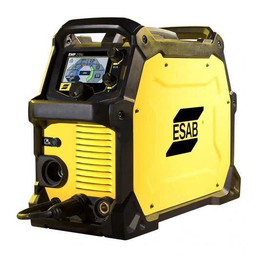
ESAB EMP 215IC Service Manual
Multi process welder
Hide thumbs
Also See for EMP 215IC:
- Instruction manual (66 pages) ,
- Instruction manual (38 pages) ,
- Instruction manual (52 pages)

Related Manuals for ESAB EMP 215IC


Summary of Contents for ESAB EMP 215IC
-
Page 1: Service Manual
ESAB EMP 215IC/EMS 215IC MULTI PROCESS WELDER Service Manual ® Revision: AA Issue Date: December 20, 2016 Manual No.: 0463 413 001 esab.com... - Page 2 WE APPRECIATE YOUR BUSINESS! Congratulations on your new ESAB product. We are proud to have you as our cus- tomer and will strive to provide you with the best service and reliability in the industry. This product is backed by our extensive warranty and world-wide service network. To locate your nearest distributor or service agency, visit us on the web at www.esab.com...
- Page 3 While the information contained in this Manual represents the Manufacturer's best judge- ment, the Manufacturer assumes no liability for its use. Multi-Process Welding Power Supply ESAB EMP215ic/EMS215ic Service Manual Number 0463 413 001 Published by: ESAB Group Inc 2800 Airport Rd.
- Page 4 Be sure this information reaches the operator. You can get extra copies through your supplier. CAUTION These INSTRUCTIONS are for experienced operators. If you are not fully familiar with the principles of operation and safe practices for arc welding and cutting equipment, we urge you to read our booklet, “Precautions and Safe Practices for Arc Welding, Cutting, and Gouging,”...
- Page 5 The RoHS Directive 2011/65/EU, entering into force 2 January 2013 Type of equipment Welding power source Type designation EMP 215ic, from serial number 615 xxx xxxx (2016 w/21) Brand name or trade mark ESAB Manufacturer or his authorised representative established within the EEA...
- Page 6 ESAB EMS215C/EMP215C This Page Intentionally Blank DECLARATION OF CONFORMITY Manual 0463 413 001...
-
Page 7: Table Of Contents
TABLE OF CONTENTS SAFETY PRECAUTIONS ................1-1 1.01 Safety precautions ..................1-1 1.02 User responsibility ..................1-6 SYSTEM INSTALLATION ................2-1 2.01 Installation ...................... 2-1 2.02 Lifting Instructions ..................2-1 2.03 Location ......................2-1 2.04 Mains Supply ....................2-2 2.05 Technical Data .................... - Page 8 TABLE OF CONTENTS REPLACEMENT PARTS ................8-1 8.01. Introduction ....................8-1 8.02. External Replacement Parts ................8-2 8.03 Internal Replacement Parts 1 CSA Systems ........... 8-3 8.04 Internal Replacement Parts 1 CE Systems ............8-4 8.05 Internal Replacement Parts 2 ................8-5 8.06 Wire Feeder Replacement Parts CSA Systems ..........
-
Page 9: Safety Precautions
ESAB EMS215C/EMP215C SAFETY PRECAUTIONS 1.01 Safety precautions MEANING OF SYMBOLS As used throughout this manual: Means Attention! Be Alert! DANGER! DANGER Means immediate hazards which, if not avoided, will result in immediate, serious personal injury or loss of life. WARNING! - Page 10 ESAB EMS215C/EMP215C PROTECT YOURSELF AND OTHERS Some welding, cutting and gouging processes are noisy and require ear protection. The arc, like the sun, emits ultraviolet (UV) and other radiation and can injure skin and eyes. Hot metal can cause burns. Training in the proper use of the processes and equipment is essential to prevent accidents.
- Page 11 ESAB EMS215C/EMP215C ELECTRICAL SHOCK Contact with live electrical parts and ground can cause severe injury or death. DO NOT use AC welding current in damp areas, if movement is confined, or if there is danger of falling. Therefore: 1. Be sure the power source frame (chassis) is connected to the ground system of the input power.
- Page 12 ESAB EMS215C/EMP215C 4. If you develop momentary eye, nose or throat irritation while operating, this is an indication that ventila- tion is not adequate. Stop work and take necessary steps to improve ventilation in the work area. Do not continue to operate if physical discomfort persists.
- Page 13 ESAB EMS215C/EMP215C WARNING EQUIPMENT MAINTENANCE Faulty or improperly maintained equipment can cause injury or death. Therefore: 1. Always have qualified personnel perform the installation, troubleshooting and maintenance work. Do not perform any electrical work unless you are qualified to perform such work.
-
Page 14: User Responsibility
1.02 User responsibility Users of ESAB equipment have the ultimate responsibility for ensuring that anyone who works on or near the equipment observes all the relevant safety precautions. Safety precautions must meet the requirements that apply to this type of equipment. The following recommendations should be observed in addition to the standard regulations that apply to the workplace. - Page 15 REFERENCE TO CAN/CSA-W117.2-06 WARNING Do not use the power source for thawing frozen pipes. CAUTION This product is solely intended for arc welding. ESAB can provide you with all necessary welding protection and accessories. Manual 0463 413 001 SAFETY INSTRUCTIONS...
- Page 16 ESAB EMS215C/EMP215C This Page Intentionally Blank SAFETY INSTRUCTIONS Manual 0463 413 001...
-
Page 17: System Installation
ESAB EMS215C/EMP215C SYSTEM INSTALLATION 2.01 Installation If you are not experienced seek help from a professional before installing. CAUTION This product is intended for industrial use. In a domestic environ- ment this product may cause radio interference. It is the user's responsibility to take adequate precautions. -
Page 18: Mains Supply
ESAB EMS215C/EMP215C 2.04 Mains Supply NOTE! Mains suppy requirments for CE version This equipment complies with IEC 61000-3-12 provided that the short-circuit power is greater than or equal to Sscmin at the interface point between the user's supply and the public system. It is the responsibility of the installer or... -
Page 19: Technical Data
Generators with Automatic Voltage Regulation (AVR) or with equivalent or better type of regulation, with rated power 8 kW, are recommended. 2.05 Technical Data EMP 215ic Voltage 230 V,1 ~ 50/60 Hz 120 V, 1 ~ 50/60 Hz Primary current 20 A Breaker: 28.6 A... - Page 20 ESAB EMS215C/EMP215C 23.0” (548 mm) × 9.0” 23.0” (548 mm) × 9.0” Dimensions L×W×H (229 mm) × 16.0” (406 mm) (229 mm) × 16.0” (406 mm) Weight 40 lbs (18.2 kg) 40 lbs (18.2 kg) Operating temperature -14 to +104 °F (-10 to +40 °C) -14 to +104 °F (-10 to +40 °C)
-
Page 21: Connecting The Power Source To Input Supply
ESAB EMS215C/EMP215C Duty cycle The duty cycle refers to the time as a percentage of a ten-minute period that you can weld at a certain current without overheating. The duty cycle is valid for 104°F / 40°C. For more information see section "Duty cycle" in the OPERATION chapter. - Page 22 ESAB EMS215C/EMP215C 120V, 20A 120V, 15A 208/230V, 50A NEMA 6-50P 230VAC plug INSTALLATION Manual 0463 413 001...
-
Page 23: Operation
ESAB EMS215IC/EMP215IC OPERATION 3.01 General General safety regulations for handling the equipment can be found in the "1 SAFETY PRECAUTIONS" chapter of this manual. Read it through before you start using the equipment! NOTE! When moving the equipment use intended handle. Never pull on the cables. - Page 24 ESAB EMS215IC/EMP215IC Saving welding programs for Seconds a specific application when in the Memory Mode Settings on user manual Cancel menu Spool Gun Remote (Not all markets) Settings Foot control Burnback Adjusting the time when the voltage stays on 2T, Trigger On/OFF...
- Page 25 ESAB EMS215IC/EMP215IC Inductance The addition of inductance into the arc characteristics to stabilize Diagnostics the arc and reduce spatter when in the short circuit process Memory, able to save welding programs for a Language selection specific application Stick electrode choice...
-
Page 26: Controls And Connections
ESAB EMS215IC/EMP215IC 3.02 Controls and Connections Front and rear: 1. Knob for current or wire feed speed selection 2. Display 3. Knob for voltage selection 4. Main knob for menu navigation 5. Torch/Remote control connection 6. Negative output [-] 7. Polarity changeover cable and receptacle connected to positive output [+] 8. -
Page 27: Connection Of Welding And Work Leads
ESAB EMS215IC/EMP215IC Drive System Diagram 1. Wire Spool Hub 2. Circuit breaker 3. Side Panel 4. Gas valve 5. Wire feeder mechanism 3.03 Connection of Welding and Work leads The power source has two outputs for connecting welding and work leads (see front illustration), a negative [-] terminal (6) and a positive [+] terminal (7). -
Page 28: Inserting And Replacing Wire
3.05 Inserting and Replacing Wire The EMS 215ic and EMP 215ic will handle wire spool sizes of 4” (100 mm) and 8” (200 mm). 1. Open the side panel. 2. Release the tension from the pressure roller by turning the adjustable wire drive tension knob in an counter-clockwise direction. -
Page 29: Setting The Wire Feed Pressure
ESAB EMS215IC/EMP215IC 3.06 Setting the Wire Feed Pressure Piece of wood WARNING Never point the torch toward you while depressing the trigger. Start by making sure that the wire moves smoothly through the wire guide. Then set the pressure of the wire feeder's pressure rollers. -
Page 30: Shielding Gas
ESAB EMS215IC/EMP215IC 3.08 Shielding Gas The choice of suitable shielding gas depends on the material. Typically mild steel is welded with mixed gas (Ar + CO2) or 100% carbon dioxide (CO2). Stainless Steel can be welded with mixed gas (Ar + CO2) or Trimix (He + Ar + CO2). - Page 31 ESAB EMS215IC/EMP215IC Manual 0463 413 001 OPERATION...
-
Page 32: Duty Cycle
3.10 Duty Cycle The EMS 215ic and EMP 215ic have a maximum welding current output of 220A at 10% duty cycle. A self- resetting thermostat will protect the power source if the duty cycle is exceeded. A different combination of duty cycle and welding current can be selected. Use the graphs below to determine the correct duty cycle for a given welding current. -
Page 33: Control Panel
ESAB EMS215IC/EMP215IC 3.11 Control Panel After power on has completed the main menu appears on the control panel. NOTE! System output status will be indicated by the screen background color. Red/Or- ange means the torch is live/hot. No trigger needed. Blue means a trigger has to be used and Green means system is in Set Up mode and not able to be activated. - Page 34 ESAB EMS215IC/EMP215IC EMS215ic sMIG mode Manual MIG mode Flux cored wire mode Stick/MMA mode Settings User manual information Dialogue box 3.11.3 sMIG mode Home screen Information Wire feed speed Material thickness Weld bead shape Voltage trim Must be in “Advanced Settings”...
- Page 35 3.11.5 Flux cored wire mode Home screen Information Wire feed speed Voltage Dialogue box 3.11.6 Stick mode SMAW (EMP 215ic only) 1. Home screen 2. Information 3. Amperage 4. Voltage (OCV or arc) 5. Stick mode ON/OFF 6. Dialogue box 3.11.7 TIG-Lift mode (EMP 215ic only)
- Page 36 ESAB EMS215IC/EMP215IC 3.11.8 Settings Reset mode Inch/Metric Basic/Advanced Language Information Home screen Dialog box 3.11.9 User Manual Information Maintenance information Spare parts Operation information Home screen Di alogue box 3-14 OPERATION Manual 0463 413 001...
-
Page 37: Service Instructions
Work surfaces, carts and containers must be conductive and grounded. Use only antistatic packaging materi- als. Overall, handling of ESD-sensitive devices should be minimized to prevent damage. Service aid ESAB can offer a number of service tools that will simplify the service. Antistatic service kit Ordering no. - Page 38 ESAB EMS215IC/EMP215IC This Page Intentionally Blank SERVICE INSTRUCTIONS Manual 0463 413 001...
-
Page 39: Power Supply Introduction
ESAB EMS215IC/EMP215IC POWER SUPPLY INTRODUCTION 5.01. Introduction Design structure of the power source The EMS215ic and EMP215ic power source is operating on the inverter principle. It consists of a number of function modules. Each module has a module number, which is always included as the first part of the name/ identification of components in the module. -
Page 40: Block Diagram
ESAB EMS215IC/EMP215IC 5.03 Block Diagram POWER SUPPLY INTRODUCTION Manual 0463 413 001... - Page 41 ESAB EMS215IC/EMP215IC This Page Intentionally Blank Manual 0463 413 001 POWER SUPPLY INTRODUCTION...
-
Page 42: System Schematic For Csa Systems
ESAB EMS215IC/EMP215IC 5.04 System Schematic for CSA Systems POWER SUPPLY INTRODUCTION Manual 0463 413 001... - Page 43 ESAB EMS215IC/EMP215IC A-12892_AA Manual 0463 413 001 POWER SUPPLY INTRODUCTION...
-
Page 44: System Schematic For Ce Systems
ESAB EMS215IC/EMP215IC 5.05 System Schematic for CE Systems A-13146_AA POWER SUPPLY INTRODUCTION Manual 0463 413 001... - Page 45 ESAB EMS215IC/EMP215IC A-13146_AA Manual 0463 413 001 POWER SUPPLY INTRODUCTION...
-
Page 46: Component Location
ESAB EMS215IC/EMP215IC 5.06 Component Location Item # Description Designator Control PCB PCB / (20AP1) Circuit Breaker On / Off Switch SW 1 Fan 1 and Fan 2 M1 and M2 PFC Inductor Output Diode PCB PCB4 Main Transformer Current Sensor... -
Page 47: Troubleshooting
ESAB EMS215IC/EMP215IC TROUBLESHOOTING 6.01 Error Codes Serverity Levels Critical Service Required - Unit not functional or locked, not recoverable Non- Service may be desired - unit functional with limit performance Critical Warning Unit functional and will recover on its own... - Page 48 ESAB EMS215IC/EMP215IC Err 008 Critical "VOLTAGE Open circuit UI Display & CN8 We start sensing this voltage only FAULT Voltage error, OKC Ctrl PCB when weld activity is expected to SERVICE voltage signal not be ocurring. If this failure happens REQUIRED"...
- Page 49 ESAB EMS215IC/EMP215IC ITEM# GRAPHIC ERROR Serverity Error Mes- Functional Circuit Where displayed Possible Cause or Repair Action SYMBOL CODE sage on Failure Explanation Display Err 020 Critical GRAPHICS No Image found UI Display ReLoad the SPI Flash with correct ERROR in Flash image.bin file.
-
Page 50: Pre Power-Up Checks
ESAB EMS215IC/EMP215IC 6.02 Pre Power-up Checks WARNING Buss voltage of 400 VDC will be present on the heatsinks of POWER PCB2 while unit is on. Wait 40 seconds after removing power before handling. Examine unit for any visible signs of damage. - Page 51 ESAB EMS215IC/EMP215IC 7. Place positive meter led on BR2 (-) terminal and negative meter lead on MAINS CABLE plug blade Line 2. Check for forward bias diode (0.3 – 0.7v) If any of the checks show a reading other than as indicated above, then the ten components will have to be checked to identify the failed component(s).
- Page 52 ESAB EMS215IC/EMP215IC 0.3 - 0.7 V Q7 Collector Q4 Collector 0.3 - 0.7 V 0.3 - 0.7 V BR2(-) 1 MAINS POWER CABLE/PLUG a. Check continuity of cable from end to end on all three leads. b. Check for short between Line 1 and Line 2.
- Page 53 ESAB EMS215IC/EMP215IC 2 SW1 ON/OFF SWITCH a. Check that mechanical switch action is crisp and positive. b. Check both halves of switch for continuity when ON and open when OFF c. Check for short between each half of switch Replace SW1 if fault is found The following image shows the previous steps listed.
- Page 54 ESAB EMS215IC/EMP215IC 5 BR1/BR2 a. Perform Diode Check on both Bridge rectifiers If either one has open or shorted diode, replace both BR1 & BR2 The following image shows the previous step listed. In the oval you will see the step number and below that the meter reading you should see.
- Page 55 ESAB EMS215IC/EMP215IC 6 PTC1/RY1 a. Measure continuity between BR1 or BR2 Positive Terminals and BUS terminals on POWER PCB2 for 23 ohms. If open or shorted replace POWER PCB2. The following image shows the previous step listed. In the oval you will see the step number and below that the meter reading you should see.
- Page 56 ESAB EMS215IC/EMP215IC 7 D49/D50 a. With Meter in Diode Check setting check for diode reading between Heatsink Terminal D50 and PFC Terminal on Power PCB2.. If open or shorted replace POWER PCB2. See following illustration 8 Q19/Q21 a. With Meter in Diode Check setting, place negative meter lead on PFC terminal on POWER PCB 2 and positive lead on BR2(–) terminal for forward biased diode (0.30-00.7VDC).
- Page 57 ESAB EMS215IC/EMP215IC 10 Q3, 4, 6, 7 Re-install wire into POWER PCB2 PFC terminal. Disconnect wire from POWER PCB2 TRANS2 terminal. a) With meter in diode setting, check for diode reading between Heatsink Terminals Q4 and Q7. b) With meter in diode setting, check for diode reading between Heatsink Terminals Q3 and Q6.
- Page 58 ESAB EMS215IC/EMP215IC An additional Pre Power-up check for the Output Diodes D66 – D69 should be performed. Using a meter set in the DIODE TEST setting do the following: 1 With positive meter lead on – OUTPUT WELD terminal and with negative meter lead on + WELD OUT- PUT terminal, check for forward biased diode drop reading.
-
Page 59: Led Diagnostics
ESAB EMS215IC/EMP215IC 6.03 LED Diagnostics The unit has several LEDs that can assist in diagnosing problems. POWER PCB2 / (15AP1) +24V_SEC OK +24VDC Supply on this pcb is present +18V_PRI OK +18VDC Supply on this pcb is present CONTROL PCB3 / (20AP1) - Page 60 ESAB EMS215IC/EMP215IC Initial Set up conditions SW1- OFF J1 – No remote device installed Connect unit to 120VAC Mains Power. Polarity Cable not connected. 1) Power-Up Test a) Turn SW1 to ON position and observe the following The unit will come up in whichever process that the unit was in when the unit was last turned off.
- Page 61 ESAB EMS215IC/EMP215IC GTAW LIFT TIG Process Test 1) Turn SW1 to Off Position. 2) Connect TIG torch power cable to negative weld output connector and work cable to positive weld output connector. 3) Connect gas hose to flow meter regulator. And turn regulator on and set flow.
- Page 62 ESAB EMS215IC/EMP215IC PCB LEDs Status POWER PCB3 D42 & D53 CONTROL PCB2 PS OK 3.3V_1 OK +24V_1 LOW BUS V ERR UI COM uP OK 10.3_VB OK +5V_10 OK MIG SOL ON TRIGGER ON TIG SOL FAN ON 1) With gun in position, activate MIG gun trigger. On CONTROL PCB3, D87 D88 will come on, gas will flow and wire will feed and arc will establish.
-
Page 63: Initial Power Up Test Problems
ESAB EMS215IC/EMP215IC 6.05 Initial Power Up Test Problems 1) Mains Power fuses blow/ breaker trips when SW1 is turned on. a) Faulty Mains Power Cable and/or Plug Check continuity – Replace if faulty b) Shorted BR1 or BR2 rectifiers. Check continuity- See sub-section 6.02 BR1/ BR2. - Page 64 ESAB EMS215IC/EMP215IC The following image shows the previous steps listed. In the oval you will see the step number and below that the meter reading you should see. 120VAC +/- 10% 208/230VAC +/- 10% 120VAC +/- 10% 208/230VAC +/- 10% 3.
- Page 65 ESAB EMS215IC/EMP215IC The following image shows the previous steps (4a and 4b) listed. In the oval you will see the step number and below that the meter reading you should see. Manual 0463 413 001 TROUBLESHOOTING 6-19...
- Page 66 ESAB EMS215IC/EMP215IC c) Defective CONTROL PCB3 (This step requires the unit be connected to power and turned on) 1) On the CONTROL PCB3 Connector CN19, Measure from pin 6 to pin 4. The voltage should be approx 1.8VDC. 2) On the Control PCB3 Connector CN19, Measure from Pin 3 to pin 4. The voltage should be less than 0.25VDC.
- Page 67 ESAB EMS215IC/EMP215IC CN17 4d 2 < 0.25 VDC 4d 1 Approximately 1.8VDC 4c 2 < 0.25 VDC 4c 1 Approximately 1.8VDC CN19 Manual 0463 413 001 TROUBLESHOOTING 6-21...
- Page 68 ESAB EMS215IC/EMP215IC SMAW Process Test Problems 1) Cannot change weld process a) Defective ENCODER PCB7 Perform ENCODER PCB Test subsection 6.06 2) No voltage between +/- Weld Output Connectors a) Defective CONTROL PCB3 D33 should be on (Very dim). If it is not on, replace Control PCB3 b) Defective OUTPUT DIODE PCB4 Perform OUTPUT DIODE PCB4 Test, see subsection 6.06...
- Page 69 ESAB EMS215IC/EMP215IC 3) No welding arc is established when electrode is touched /lifted off the work piece. a) Open or poor work cable connection b) Open TIG Torch lead c) Problem in the remote control start (Trigger) circuit. Perform REMOTE CONTROL START (TRIGGER) Test, see subsection 6.06 d) Defective Control PCB3 Check LED D33 is on (Very dim) when trigger is active.
- Page 70 ESAB EMS215IC/EMP215IC The following image shows the previous steps (2c , 3a and 3b) listed. In the oval you will see the step number and below that the meter reading you should see. CN10 5 VDC 1-24 VDC 0.0 VDC...
-
Page 71: Test Procedure/Troubleshooting
ESAB EMS215IC/EMP215IC 6.06 Test Procedure/troubleshooting POWER PCB2 - Power Supply Test 1) Measure for Mains voltage on POWER PCB2 between terminals LINE1 to LINE2. 2) Check LEDs Status +24V_SEC OK +18VDC_PRI OK 3) Measure for 400VDC buss voltage between terminals LINE+ to LINE-. - Page 72 ESAB EMS215IC/EMP215IC CONTROL PCB3 - Power Supply Test 1) Check PCB LEDs status as follows PS OK 3.3V_1 OK +24V_1 LOW 10.3_VB OK +5V_10 OK If problem is found, remove power, disconnect the harness connectors from CONTROL PCB3 connector CN6.
- Page 73 ESAB EMS215IC/EMP215IC OUTPUT DIODE PCB4 Test 1) Disconnect and isolate T1 transformer wires from Terminals SEC1 & SEC2. 2) With negative meter lead on + Welding Output Connector, place positive meter lead on SEC1, then SEC2 terminal. Check for forward biased diode drop reading.
- Page 74 ESAB EMS215IC/EMP215IC The following image shows the previous steps listed. In the oval you will see the step number and below that the meter reading you should see. +15 VDC -15 VDC CN18 4c 2 0.0 VDC No load 4c 1 0.5VDC / 100A...
-
Page 75: Pcb Layout
ESAB EMS215IC/EMP215IC REMOTE CONTROL START (TRIGGER) Test LED D88 (TRIGGER ON), located on CONTROL PCB3, is normally OFF. PCB3 applies either a 12VAC (230VAC line voltage) or 6vac (115vac line voltage) to CN5 Pins 3 &4 which connects to the front panel Remote Control Connector J1, Pins 2&3. - Page 76 ESAB EMS215IC/EMP215IC Control PCB D87 MIG SOL ON D89 TIG SOL ON D33 PWM R34 CURRENT CALIBRATION POT D36 3.3V_1 OK D45 P OK D44 UI COM D43 BUSS V ERROR D40 +24V_1 LOW D88 TRIGGER R642 WIRE FEED SPEED CALIBRATION...
- Page 77 ESAB EMS215IC/EMP215IC Main PCB Line - Line + Line 2 Line 1 D42 +24V_SEC OK D53 +18V_PRI OK TRANSF1 TRANSF2 Output Diode PCB Manual 0463 413 001 TROUBLESHOOTING 6-31...
- Page 78 ESAB EMS215IC/EMP215IC This Page Intentionally Blank 6-32 TROUBLESHOOTING Manual 0463 413 001...
-
Page 79: Maintenance
ESAB EMS215IC/EMP215IC MAINTENANCE NOTE! Regular maintenance is important for safe, reliable operation CAUTION Only persons with the appropriate electrical knowledge (authorized personnel) may remove the cover of the product to connect or carry out service, maintenance or repair work on the welding equipment. -
Page 80: Power Source And Wire Feeder Maintenance
ESAB EMS215IC/EMP215IC 7.02 Power Source and Wire Feeder Maintenance Perform a power source cleaning each time you replace a Ø4” (100 mm) or Ø8” (200 mm) wire bobbin. Power source and wire feeder cleaning procedure NOTE! Always were safety gloves during cleaning. -
Page 81: Replacement Parts
Note 0558 102 239 EM 215ic Wire Reel Size Ø4-8" (100-200 mm). CSA/Bayonet 0558 102 240 EMP 215ic Wire Reel Size Ø4-8" (100-200 mm). CSA/Bayonet 0700 300 985 EMP215ic Bobbin Ø 100-200mm (4-8") CE, Euro Connection Manual 0463 413 001... -
Page 82: 8.02. External Replacement Parts
ESAB EMS215IC/EMP215IC 8.02. External Replacement Parts Item Ordering no. Description Notes 0558 102 404 Side panel Left With ESAB logo and welding decal Screw M4 × 8 mm 0558 102 406 Hinge M4 × 0.7 mm 0558 102 407 Hinge pin... -
Page 83: Internal Replacement Parts 1 Csa Systems
ESAB EMS215IC/EMP215IC 8.03 Internal Replacement Parts 1 CSA Systems Item Ordering no. Description Notes 0558 102 414 Female Inert Gas Fitting 0558 102 415 ON / OFF switch TFT Display shell 0558 102 422 User Interface PCB PCB1 / (1AP1) -
Page 84: Internal Replacement Parts 1 Ce Systems
ESAB EMS215IC/EMP215IC 8.04 Internal Replacement Parts 1 CE Systems Item Ordering no. Description Notes 0558 102 414 Female Inert Gas Fitting 0558 102 415 ON / OFF switch TFT Display shell 0558 102 422 User Interface PCB PCB1 / (1AP1) -
Page 85: Internal Replacement Parts 2
ESAB EMS215IC/EMP215IC 8.05 Internal Replacement Parts 2 Item Ordering no. Description Notes 0558 102 416 Circuit Breaker 0558 102 415 ON / OFF Switch 0558 102 427 Control PCB PCB3 / (20AP1) 0558 102 426 Power PCB Assembly PCB2 / (15AP1) 0558 102 420 Fan 1&2... -
Page 86: Wire Feeder Replacement Parts Csa Systems
ESAB EMS215IC/EMP215IC 0558 102 430 Output Inductor 0558 102 417 Current Sensor CS1 / (15AP3) 8.06 Wire Feeder Replacement Parts CSA Systems Item Ordering no. Description Wire type Wire dimensions 0558 102 326 Wire outlet guide MS/SS/Flux Cored 0.030” / 0.035” / 0.045” (0.8 mm / 0.9 mm / 1.2 mm) -
Page 87: Wire Feeder Replacement Parts Ce Systems
ESAB EMS215IC/EMP215IC 8.07 Wire Feeder Replacement Parts CE Systems Item Ordering no. Description Wire type Wire dimensions 0558 102 460 Wire outlet guide MS/SS/Flux 0.8 mm / 0.9 mm / 1.2 mm Cored (0.030” / 0.035” / 0.045”) 0558 102 461... - Page 88 ESAB EMS215IC/EMP215IC This Page Intentionally Blank REPLACEMENT PARTS Manual 0463 413 001...
-
Page 89: Disassembly
ESAB EMS215IC/EMP215IC DISASSEMBLY 9.01 Safety Precautions for Disassembly WARNING Read and follow safety information in Section 1 before proceeding. Follow anti static precautions when handling any PCB (Printed Circuit Board). WARNING Buss voltage of 400 VDC will be present on the heatsinks of POWER PCB2 while unit is on. - Page 90 ESAB EMS215IC/EMP215IC 2. Unplug the small multi wire harness from CN6 on the bottom of the Control PCB. (Not shown) 3. Remove the four (4) screws on the inside of the unit that secure the User Interface TFT Display in place.
-
Page 91: Control Pcb Removal
ESAB EMS215IC/EMP215IC 9.03 Control PCB Removal Read and follow safety information in Section 1 before proceeding with disassembly. Follow anti static precautions when handling any PCB (Printed Circuit Board). Unplug the unit before beginning disassembly procedure. 1. Remove eight (8) screws securing the power-side cover and frame to the power supply. -
Page 92: Power Pcb Assembly Removal
ESAB EMS215IC/EMP215IC 9.04 Power PCB Assembly Removal WARNING Read and follow safety information in Section 1 before proceeding. Follow anti static precautions when handling any PCB (Printed Circuit Board). NOTE! The Control PCB must be removed before you can remove the Power PCB Assembly.. -
Page 93: Appendix 1: Working Principle (Block Diagram
ESAB EMS215IC/EMP215IC APPENDIX 1: WORKING PRINCIPLE (BLOCK DIAGRAM) Manual 0463 413 001 APPENDIX... -
Page 94: Appendix 2: Csa System Schematic, 115/230V Units
ESAB EMS215IC/EMP215IC APPENDIX 2: CSA SYSTEM SCHEMATIC, 115/230V UNITS APPENDIX Manual 0463 413 001... - Page 95 ESAB EMS215IC/EMP215IC A-12892_AA Manual 0463 413 001 APPENDIX...
-
Page 96: Appendix 3: Ce System Schematic, 115/230V Units
ESAB EMS215IC/EMP215IC APPENDIX 3: CE SYSTEM SCHEMATIC, 115/230V UNITS A-13146_AA APPENDIX Manual 0463 413 001... - Page 97 ESAB EMS215IC/EMP215IC A-13146_AA Manual 0463 413 001 APPENDIX...
- Page 98 ESAB EMS215IC/EMP215IC Calibration This section provides qualified service personnel detailed instructions to calibrate the Rebel control PCB when in an assembled unit. The control PCB will require calibration when: 1. The Control PCB, PCB3 has been replaced, 2. The Wire Feed Mechanism M1 has been replaced, 3.
- Page 99 ESAB EMS215IC/EMP215IC This Page Intentionally Blank Manual 0463 413 001 APPENDIX...
-
Page 100: Revision History
ESAB EMS215IC/EMP215IC Revision History Date Rev Description Dec. 20, 2016 Manual release APPENDIX Manual 0463 413 001... - Page 101 This Page Intentionally Blank...
- Page 102 THE NETHERLANDS ESAB Asia/Pacific Pte Ltd ESAB Nederland B.V. Singapore Amersfoort Tel: +65 6861 43 22 Tel: +31 33 422 35 55 Fax: +65 6861 31 95 Fax: +31 33 422 35 44 www.esab.eu ©2016 ESAB Welding and Cutting Products...
Need help?
Do you have a question about the EMP 215IC and is the answer not in the manual?
Questions and answers
Esab machine alarm help me pleas
The ESAB EMP 215IC machine has common alarms related to power, overheating, and electrical issues. Here’s how to resolve them:
1. No Arc
- Ensure the electrical power supply switch is turned on.
- Check that the mains, welding, and return cables are correctly connected.
- Verify that the correct current value is set.
- Inspect the electrical power supply fuses.
2. Overheating Protection Trips Frequently
- Ensure the duty cycle for the selected weld current is not exceeded.
- Check that air inlets and outlets are not clogged.
3. Low or Missing Voltage on PCB
- Check LED diagnostics for power supply issues.
- If LED D40 (+24V_1 LOW) is on, the +24VDC supply is low.
- If LED D43 (BUS V ERROR) is on, there is a bus voltage issue.
For further electrical issues, testing components like the output diode PCB and ensuring correct connections may be necessary. Repairs should be done by an authorized ESAB service technician.
This answer is automatically generated