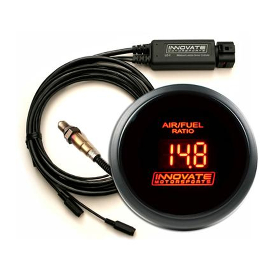
Innovate Motorsports LC-1 User Manual
Digital air/fuel ratio (lambda) sensor controller
Hide thumbs
Also See for LC-1:
- Manual (1 page) ,
- Quick start manual (2 pages) ,
- Quick start manual (2 pages)
Table of Contents
Advertisement
LC-1 Digital Air/Fuel Ratio (Lambda)
Sensor Controller Manual
Warning!
The Oxygen Sensor used in this device gets very hot in operation.
Do not touch the hot sensor. Do not let a hot sensor touch a
combustible surface. Do not use the sensor with or near flammable
liquids or gases. Failure to heed these warnings may result in severe
burns, explosions or fires.
When installed in the exhaust, the oxygen sensor MUST be
connected and operating with the LC-1 whenever the car is running.
An un-powered oxygen sensor will be quickly damaged when
exposed to hot exhaust gases.
Document # 11-0053
11-0053 LC-1_Manual_1.6.doc
Advertisement
Table of Contents
Troubleshooting

Related Manuals for Innovate Motorsports LC-1


Summary of Contents for Innovate Motorsports LC-1
- Page 1 Failure to heed these warnings may result in severe burns, explosions or fires. When installed in the exhaust, the oxygen sensor MUST be connected and operating with the LC-1 whenever the car is running. An un-powered oxygen sensor will be quickly damaged when exposed to hot exhaust gases.
-
Page 2: Table Of Contents
Indicator LED and Calibration button hookup: ..............5 Connecting the LC-1 to an external analog AFR display..........5 Connecting the LC-1 to an ECU or data logger ..............5 Mounting the sensor using a Bung................... 6 How to fabricate a copper heat sink ................. 8 First Time Use .......................... -
Page 3: Overview
1 Overview The LC-1 is a stand-alone Wideband Controller used to measure the Air/Fuel Ratio (AFR) or Lambda for an engine. For gasoline-driven engines, the theoretically optimal air fuel ratio is 14.7 pounds of air for every pound of fuel. At this ratio, theoretically, all available oxygen in the air combines with all available fuel. -
Page 4: Mounting And Connecting The Lc-1
B. Serial In connection, 2.5mm stereo (female) marked as IN C. Serial Out connection, 2.5 mm stereo (female) marked as OUT. * 3.1 If you have an LC-1 with only 6 stripped ends (early production) the wiring is as follows: a. Red 12V supply b. -
Page 5: Indicator Led And Calibration Button Hookup
2.1 Indicator LED and Calibration button hookup: To monitor LC-1 status, connect the red wire (Anode) of the included LED to the calibration wire (black) of the LC-1 and connect the black wire (Cathode) of the LED to the ground wire of the momentary switch. -
Page 6: Mounting The Sensor Using A Bung
Install the oxygen sensor’s bung upstream from the catalytic converter (a bung and plug is included in the LC-1 kit). Any decent muffler or exhaust shop can do this for you. The wide- band oxygen sensor is then installed into the bung to take a reading. (Insert the plug into the bung when not in use). - Page 7 It is NOT a good idea to connect the LC-1 permanently to 12V and switch it on with a separate switch before the vehicle is started. Depending on the climate...
-
Page 8: How To Fabricate A Copper Heat Sink
3 First Time Use 1. Do not connect the sensor yet. 2. Switch 12V supply to the LC-1 on and wait for 10 seconds. 3. Switch the 12V supply off after 10 seconds. 4. Connect the sensor to the sensor interface connector. The sensor must be exposed to air for the first time calibration. -
Page 9: Calibration
After that period the LC-1 will automatically perform a free air calibration. During this 2 second period a connected LED will go off. The LC-1 will now calibrate itself by using air as a reference gas with known oxygen content. -
Page 10: Calibration Schedule
AFR meters. With the LC-1, connecting these meters to the second analog output of the LC-1 allows them to be used as true remote AFR meters, provided the LC-1 analog output is programmed to the characteristics of the used meter. -
Page 11: Multi Channel Afr Recording With Multiple Lc-1'S And/Or Lm-1
5.4 Multi channel AFR recording with multiple LC-1’s and/or LM-1 If multiple LC-1’s are used, connect the Serial OUT of the first LC-1 to the Serial IN of the next one. Connect the serial out of that one again to the Serial IN of the next one and so on. -
Page 12: Programming The Lc-1
Start the LM-Programmer software. The screen should look like this: On this page you can see the software version of the LC-1 and you can change the multiplier to calculate AFR from Lambda. A number of different multipliers are already pre-selectable but you can change it to a custom one for the particular fuel you are using. -
Page 13: Resetting The Calibration Data
99.9% of the time. While we don’t anticipate this occurring, it is possible that the LC-1 will not recover correctly and may need to be serviced at our factory. If you suspect this is the case, contact Innovate support. -
Page 14: Advanced Output Programming
AFR of 22.39. Other curves of course are easily programmable 6.5.1 Advanced output programming The normal state of the analog outputs is to update the outputs every time the LC-1 takes a new measurement. The LC-1 is fast enough to distinguish individual pockets of exhaust gas. For many applications this will be too fast. -
Page 15: Tips, Tricks And Troubleshooting
LC-1 will report a sensor timing error. The oxygen sensor needs to have the back part of the sensor (where the wires enter the sensor) exposed to outside air. -
Page 16: Sensor Timing Errors
Sometimes it’s possible to encounter Error 08 when the exhaust gas suddenly gets too rich. Normally the LC-1 will display a ‘too rich’ indication if the exhaust gas is too rich. If the mixture gets rich very suddenly, the LC-1 cannot distinguish between a too rich condition and a sensor timing error. - Page 17 1, 2, 3 or 4 wire sensors. The analog output connector of the LC-1 can simulate the operation of a narrow band sensor while the wide-band oxygen sensor is installed in place of the OEM narrow-band sensor. Factory equipped Analog output 1 of the LC-1 is programmed to simulate a narrow band sensor.
-
Page 18: Appendix A: Lc-1 Cable Pinouts
Vehicle has a 4-wire sensor Typically the 4 wires are: heater power, heater ground, sensor ground, and sensor element connection. Proceed as for the 3-wire sensor. Appendix A: LC-1 Cable Pinouts A1. Sensor Interface Connector (Standard DIN-5 female) Lambda Meter Signal... -
Page 19: Appendix B: Led Blinking Codes
Appendix B: LED blinking codes 1. Blinking steady about 2 times/second: Warming up 2. Blinking steady at about 4 times/second: Heater calibration 3. LED off No Power or free air calibration 4. Blink sequence with 2 second pause Error indication Error indication details: Count the number of fast flashes between 2 second pauses. -
Page 20: Appendix C: Lc-1 Error Codes And Troubleshooting Tips
Appendix C: LC-1 Error Codes and Troubleshooting Tips Error Error Message Likely Root Cause Code Heater circuit shorted 1. Short in cable 1. Repair/replace cable. Error 1 2. Short in sensor 2. Replace sensor. Heater circuit open 1. Damaged sensor cable or 1. -
Page 21: Appendix C: Limited Warranty
Appendix C: Limited Warranty LIMITED WARRANTY Innovate stands behind the quality of its products. Innovate makes the following warranty to purchasers of its products: All new Innovate products carry a six-month warranty from the date of purchase. If proof of purchase cannot be provided, warranty will be determined by date of manufacture. -
Page 22: Revision History
Revision History – 1/23/05 Initial release. 1.1 – 5/16/05 Corrected error in section 6.4 1.2 – 5/26/05 Updates to section 3 1.3 – 11/03/05 Update Chapter 2 1.4 – 03/01/06 Update Chapter 2 1.5 – 03/16/06 Added Push Button/ LED, Calibration Schedule, and updated wiring schematic 1.6 –...
Need help?
Do you have a question about the LC-1 and is the answer not in the manual?
Questions and answers