Table of Contents
Advertisement
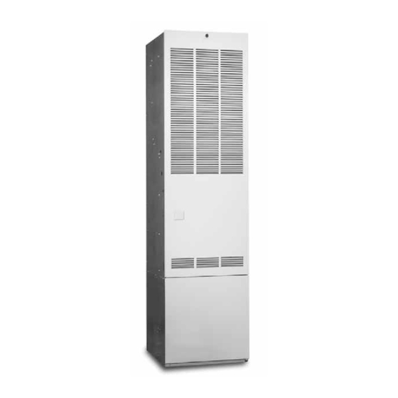
M1B, M1M & M5S Series
InstallatIon InstRuctIons
Downflow, Direct Vent (Sealed Combustion)
Forced Air Gas & Oil Furnaces
For installation in:
• Manufactured Homes
• RecreationalVehicles,Park Models,& Manufactured
Buildings
• Modular Homes / Buildings
FIRE oR EXPlosIon HaZaRD
• Failure to follow safety warnings exactly
could result in serious injury or property
damage.
• Installation and service must be performed
by a qualified installer, service agency or
the gas supplier.
• Do not store or use gasoline or other
flammable vapors and liquids in the vicinity
of this or any other appliance.
WHat to Do IF You sMEll Gas
• Do not try to light any appliance.
• Do not touch any electrical switch; do not
use any phone in your building.
• leave the building immediately.
• Immediately call your gas supplier from a
neighbors phone. Follow the gas suppliers
instructions.
• If you cannot reach your gas supplier, call
the fire department.
Do not DEstRoY. PlEasE REaD caREFullY & KEEP In a saFE PlacE FoR FutuRE REFEREncE.
WaRnInG / aVERtIssEMEnt
RIsQuE D'IncEnDIE ou D' EXPlosIon
• le non-respect des avertissements de sécurité
pourrait entraîner des blessures graves, la mort
ou des dommages matériels.
• l'installation et l'entretien doivent être effectués
par un installateur qualifié, un organisme de
service ou le fournisseur de gazstaller, service
agency or the gas supplier.
• ne pas entreposer ni utiliser de l'essence ni
d'autres vapeurs ou liquides inflammables dans le
voisinage de cet appareil,ni de tout autre appareil.
QuE FaIRE s'Il Y a unE oDEuR DE GaZ
• ne pas tenter d'allumer aucun appareil.
• ne toucher à aucun interrupteur électrique;
n'utiliser aucun téléphone dans le bâtiment.
• Évacuer l'immeuble immédiatement.
• appeler immédiatement le fournisseur de gaz en
employant le téléphone d'un voisin. Respecter à
la lettre les instructions du fournisseur de gaz.
• si personne ne répond, appeler le service des
incendies.
Advertisement
Table of Contents

Related Manuals for Intertherm M1B Series


Summary of Contents for Intertherm M1B Series
- Page 1 M1B, M1M & M5S Series InstallatIon InstRuctIons Downflow, Direct Vent (Sealed Combustion) Forced Air Gas & Oil Furnaces For installation in: • Manufactured Homes • RecreationalVehicles,Park Models,& Manufactured Buildings • Modular Homes / Buildings WaRnInG / aVERtIssEMEnt RIsQuE D’IncEnDIE ou D’ EXPlosIon FIRE oR EXPlosIon HaZaRD •...
-
Page 2: Table Of Contents
taBlE oF contEnts IMPoRtant saFEtY InFoRMatIon ..... 3 staRtuP & aDJustMEnts ........22 M1M Operating Instructions ........23 REQuIREMEnts & coDEs ........3 How to Shut Off Gas - Direct Ignition ....23 M5S Operating Instructions ........23 GEnERal InFoRMatIon ........5 Manufacturer Warranty .......... -
Page 3: Important Safety Information
IMPoRtant saFEtY InFoRMatIon REQuIREMEnts & coDEs Safety markings are used frequently throughout this • This furnace must be installed in accordance with manual to designate a degree or level of seriousness and these instructions, all applicable local building codes should not be ignored. WaRnInG indicates a potentially and the current revision of the National Fuel Gas Code hazardous situation that if not avoided, could result in (NFPA54/ANSI Z223.1) or the Natural Gas and Propane... - Page 4 Additional information listed below is for reference purposes only • The Commonwealth of Massachusetts requires and does not necessarily have jurisdiction over local or state compliance with regulation 248 CMR 4.00 and 5.00 for codes. Always consult with local authorities before installing installation of through –...
-
Page 5: General Information
GEnERal InFoRMatIon installation clearances listed in Table 1 and in Figure 4 (page • Alcove installations: minimum 18” clearance at front cautIon: of furnace shall be provided for future servicing. A removable access panel should be installed between • Do not alter or modify this furnace or any of top of the furnace door frame and the ceiling. - Page 6 Table 1 Figure 1 Figure 2 Figure 3 all MoDEls closEt alcoVE Front 6” 18” 6" (152 mm) Top Clearance Back 0” 0” Sides 0” 0” Roof Jack 0” 0” Removable access panel should be 6” 6” 0" Side installed above Clearance furnace door frame to Furnace...
-
Page 7: Circulating Air Requirements
cIRculatInG aIR REQuIREMEnts • Noncombustible pans having 1” upturned flanges are located beneath openings in a floor duct system. • Wiring materials located in the return duct system shall WaRnInG: conform to Articles 300-22 of the National Electrical Code (ANSI C1/NFPA-70). Do not allow combustion products to enter the •... -
Page 8: Furnace Installation
FuRnacE InstallatIon locating & cutting Duct openings Floor cut-outs and fuel line holes must be carefully located notE: These Installation procedures are suggested for to avoid misalignment of the furnace, and vent piping. typical furnace installations. Since each installation is To locate standard ducts see Figure 6 (page 9). -
Page 9: Alternate Attachment Method
Figure 9 Figure 6 20" 14 1/2" 2 3/4" FLOOR OPENING “X” REAR WALL OF CLOSET OR ALCOVE 2 1/4" SUPPLY AIR DUCT FLOOR FLOOR CUT-OUT CAVITY FOR STANDARD DUCT CONNECTORS Figure 9. Floor cavity CUT-OUT FOR 1 3/4" Table 3 OPTIONAL 3/4"... -
Page 10: Round Duct Connector Installation
Round Duct connector Installation Figure 10 1. Apply a bead of caulking, mastic, or other approved sealant around bottom side of connector. 2. Install and center the duct connector in the floor opening. DUCT CONNECTOR 3. Install the mounting plate under the back side of the SUPPLY duct connector. -
Page 11: Roof Jack Installation
RooF JacK InstallatIon Figure 15 Required ceiling and roof cut-out openings must be SLIDE FURNACE BACK AGAINST carefully located to avoid misalignment of the furnace MTG. PLATE and Roof Jack. notE: Install only Roof Jack Assemblies MTG. PLATE TABS listed in Table 4 on this heating appliance. SUPPLY AIR DUCT Roof Jack selection... -
Page 12: Locating & Cutting Roof/Ceiling Openings
Figure 18 Figure 19 20" ROOF JACK WITH /12 SLANT FLASHING 10" REAR WALL OF CLOSET OR ALCOVE SLANT DECK 5/12 ROOF SLOPE 24" Figure 18. Example of 2½ / 12 slant Jack with Flashing FURNACE OUTER Table 5 DOOR slant DEcK “X”... -
Page 13: Installation Of Transit-Mode Venting System
Figure 23 Figure 20 Secure roof jack with appropriate fasteners after connecting to UPPER ROOF furnace JACK (CROWN) SCREWS WEATHER CAP Caulk under roof Roof flashing to prevent FLASHING COMPLETED water leakage ASSEMBLY Ceiling OUTER PIPE TO FURNACE INNER FLUE Optional 2-piece ceiling PIPE ring #902521... -
Page 14: Electrical Information
Line Voltage Wiring Figure 24 On-Off Thermostat Wires Switch WaRnInG: Furnace Control Box Blower to avoid electric shock, personal injury, or death, Plug To combustion turn off the electric power at the disconnect or the Blower or Flame main service panel before making any electrical Power Roll-out Switch connections. -
Page 15: Low Voltage Wiring
Low Voltage Wiring Connecting Thermostat Wires • The furnace is designed to be controlled by a 24 VAC 1. Insert 24 volt wires through the plastic grommet just thermostat. The thermostat’s wiring must comply with above the control panel. the current provisions of the NEC (ANSI/NFPA 70) and 2. - Page 16 Table 6 FuRnacE FuRnacE caBInEt NOMINAL MaXIMuM MInIMuM MaXIMuM MInIMuM MaXIMuM MInIMuM MaXIMuM MoDEl InPut WIDtH ElEctRIcal oPERatInG oPERatInG FuRnacE WIRE FusE oR cIRcuIt cIRcuIt oVERcuRREnt nuMBER- (BtuH) (IN.) suPPlY VoltaGE VoltaGE aMPEREs GauGE BREaKER aMPs* aMPacItY PRotEctIon M1MB 056 56,000 19 3/4 115-1-60...
-
Page 17: Fuel Supply & Piping
FuEl suPPlY & PIPInG WaRnInG: WaRnInG: all piping must conform with local building codes, FIRE oR EXPlosIon HaZaRD or in the absence of local codes, with the most • Failure to follow safety warnings exactly could recent edition of the national Fuel Gas code result in serious injury or property damage. -
Page 18: Leak Check
leak check notE: Optional fuel inlet lines are available for all gas furnace models to permit the addition of a 1/2” F.P.T. shut-off valve above the floor. WaRnInG: The gas supply to your home will either be Natural Gas or L.P. (bottle gas). Your furnace is factory equipped to FIRE oR EXPlosIon HaZaRD operate on Natural Gas. -
Page 19: One-Line System
Figure 27 Cordset Bypass Solenoid Valve Pressure Adjustment Screw Nozzle Port 3/16 Flare Fitting Beckett Inlet Port INLET 1/4 NPTF 3/8" Oil Supply Line USE ONLY WITH VALVE ON DELAY Flue Gas A2EA-6520 4 GPH 100-150 PSI 3450 RPM NO. 2 & LIGHTER FUEL Vent with cap Furnace 3 GPH 150-200 PSI 3450 RPM... -
Page 20: Priming Furnaces Equipped With Honeywell
Priming furnaces equipped with Honeywell Atmospheric & Direct Ignition Furnaces 1. Follow the instructions “How to Shut Off Gas” (page R7184 primary control: 23). 1. While the ignition is on, press for 1/2 second (or less), 2. Disconnect the gas pipe union and the electrical wires and release the reset button. -
Page 21: Flue Gas Sampling
32). Flue Gas sampling It may be necessary to take flue gas sampling from oil and gas furnaces (M5S and M1B Series Models) in order to check the performance after furnace installation. A M11678 flue gas sample may be taken from the heat exchanger, Figure 28. -
Page 22: Startup & Adjustments
staRtuP & aDJustMEnts PlEasE REaD all saFEtY InFoRMatIon BEFoRE lIGHtInG tHE FuRnacE WaRnInG: WaRnInG: Before placing the furnace in service, it must be FIRE oR EXPlosIon HaZaRD checked to ensure it is equipped for the type of gas • Failure to follow safety warnings exactly could being used. -
Page 23: M1M Operating Instructions
M1M operating Instructions • Honeywell (Figure 30): Turn gas control knob clockwise to OFF, Robertshaw (Figure 31): Push the gas control (Direct Ignition Furnaces) lever to OFF. Direct ignition furnaces do not have a pilot. Ignition is • For oil, shut off all valves. accomplished by a silicon carbide hot surface ignitor. -
Page 24: How To Shut Off Gas - Oil & Gas Gun
5. Wait 10 minutes to clear out any gas. If you smell gas, The furnace is equipped with a multi-speed motor. Refer stoP! and follow the safety information. If gas is to the furnace wiring diagram, Figure 38 (page 34) &... -
Page 25: Gas Gun (M1B Models)
oPERatInG sEQuEncE Gas Gun (M1B Models) Combustion air box adjustment is made to the main burner Direct Ignition Furnaces (M1M Models) by loosening the two lock nuts on the plastic air shutter, 1. On a call for heat, the thermostat contacts close, located on the left side of the burner blower housing. -
Page 26: Gas Gun Furnaces (M1B Models)
5. The circulating air blower will energize after the Gas Valve: The gas valves for the gas furnaces are a temperature fan switch closes. 100% shut-off type and will fail safe, if for some reason the gas is turned off. The valve is a “slow-open” for M1M and 6. -
Page 27: Troubleshooting
tRouBlEsHootInG Control Module is Powered - Ignitor won’t Heat Up Direct Ignition Furnaces (M1M Models) & 1. Disconnect ignitor leads at AMP receptacle and check Gas Gun Furnaces (M1B Models) for 120 volts at the plug during ignition sequence. High Gas Bills 2. -
Page 28: Oil Gun - Honeywell R7184 Or Beckett 7505 Controls Only - M5S Series
oil Gun - Honeywell R7184 or Beckett 7505 4. If the LED continues to flash at the interval listed above, verify that the control is not in restricted mode. controls only - M5s series. If in restricted mode, reset it. If not in restricted mode, Burner does not start with a call for heat replace the control. -
Page 29: Optional Accessories
oPtIonal accEssoRIEs Table 9 contRol MoDulE status InDIcatoRs - M1M sERIEs necessary when the Furnace is used with some RED lED status Central Air Conditioners InDIcatoR If an air conditioner is installed that does not use the furnace Steady ON Control OK blower for air distribution and operates independently of Steady OFF... -
Page 30: Maintenance
optional add-on air conditioning WaRnInG: Whether split system or single package, an energy- saving NORDYNE Air Conditioner is available that has use of furnace or air conditioning components been designed specifically for manufactured housing that are not included in the certification of applications and can best handle your home comfort this appliance may create a hazard, invalidate needs. -
Page 31: Figures & Tables
FIGuREs & taBlEs Table 10 oRIFIcE no FuRnacE InPut outPut E.s.P. IGnItoR COMB. MotoR a/c REaDY MoDEl # MBtu/H MBtu/H IN WC noZZlE DIREct BloWER TONS NAT. M1MB 056 M1MC 056 M1MB 070 M1MC 070 M1MB 077 M1MC 077 M1MB 090 M1MC 090 M1BB 066 M1BC 066... -
Page 32: Table 11. Equivalent Orifice Sizes For High Altitude Installations
Table 11 altItuDE - FEEt FuRnacE oRIFIcE sIZE & MoDEls outPut caPacItY 2,000 3,000 4,000 5,000 6,000 7,000 8,000 9,000 10,000 lEVEl Orifice Size - Nat. Gas Orifice Size - LP M1M - 056 Output - MBTUH 45.4 41.8 40.1 38.5 37.0 35.5... -
Page 33: Gas Information
Gas Information Table 13 Gas FloW RatEs Gas FloW RatEs (cuBIc FEEt PER HouR) (cuBIc FEEt PER HouR) cuBIc FEEt PER cuBIc FEEt PER tIME FoR tIME FoR REVolutIon oF Gas MEtER REVolutIon oF Gas MEtER onE REVolutIon onE REVolutIon (sEconDs) (sEconDs) 1,800... -
Page 34: Electrical Information
Electrical Information Figure 38 WIRING DIAGRAM Gas Direct Ignition Furnace, Heating & A/C Ready, M1M All Models. NOTES 1. Incoming power must be polarized. Observe color coding. (See furnace data label for electrical information.) 2. If any of the original wires (as supplied with the appliance) must be replaced, use 105˚C Thermoplastic BLOWER BLOWER... -
Page 35: Figure 39. Gas And Oil Furnaces, A/C Ready M1B & M5S (066, 086) Models
Figure 39 WIRING DIAGRAM & NOTES: 1. Incoming power must be polarized. Observe color coding. 4. A/C Heating Speeds: Refer to Table 12, A/C Blower Selection (See furnace data label for electrical information.) 5. If any of the original wire supplied with the appliance is replaced, 2. -
Page 36: Installation / Performance Check List
InstallatIon / PERFoRMancE cHEcK lIst ElEctRIcal sYstEM attEntIon InstallERs: Electrical connections tight? It is your responsibility to know this product better than your customer. This includes being able to install the product according to strict Line voltage polarity correct? safety guidelines and instructing the customer on how to operate Supply Voltage: ________________________________ VOLTS and maintain the equipment for the life of the product.
Need help?
Do you have a question about the M1B Series and is the answer not in the manual?
Questions and answers