
Related Manuals for Alunar M508


Summary of Contents for Alunar M508
- Page 1 ALUNAR 3D Printer M508 Quick Start Guide Service Skype:alunar3d@hotmail.com Service Email:service@alunar.net...
-
Page 2: Table Of Contents
5. Preinstallation Checklist ..............................4 5.1 Step Way of Opening Box ............................. 4 5.2 Take an account of kits ............................4 6. Assembly and Calibration for M508 ..........................4 6.1 The main machine structure ..........................5 6.2 Step1 Frame assembly ............................5 6.3 Step2 Y axis assembly and hotbed assembly.................... -
Page 3: Foreword
Foreword Thanks in advance for choosing our M508 3D Printer! With the Quick Start Guide (hereinafter as “Guide”), you could enjoy accomplishing the assembly, Test and Printing step by step. Meanwhile, you will also learn the structure principle and its special FDM printing technology deeply, and then you will get great progress on not only the theoretical knowledge but also the manipulative ability. -
Page 4: Preparatory Work
(except leading by the inartificial reason). We will try our best to settle your problems as soon as possible). 6. Assembly and Calibration for M508 M508 assembly: Please assembly the printer by following the step1- step7 on assembly diagram and video, and pay attention the prompt for key of assembling.(SD-Card: \Installation Instruction\Video) -
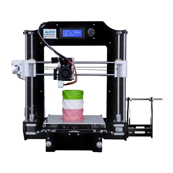
Page 5: The Main Machine Structure
6.1 The main machine structure 6.2 Step1 Frame assembly (SD-Card: \Installation Instruction\Video\1-Frame assembly.mp4) Video... -
Page 6: Step2 Y Axis Assembly And Hotbed Assembly
6.3 Step2 Y axis assembly and hotbed assembly (SD-Card: \Installation Instruction\Video\2-Y-Axis and Hot bed Assembly.mp4) Video... -
Page 10: Step3 Z Axis Assembly And X Axis Assembly
6.4 Step3 Z axis assembly and X axis assembly (SD-Card: \Installation Instruction\Video\ 3-Z-X-Axis Assembly.mp4) Video... -
Page 13: Step4 Extruder Assembly
6.5 Step4 Extruder assembly (SD-Card: \Installation Instruction\Video\ 4-Extruder Assembly.mp4) Video... -
Page 15: Step5 Lcd Assembly
6.6 Step5 LCD assembly Video (SD-Card: \Installation Instruction\Video\ 5-LCD-Assembly.mp4) -
Page 16: Step6 Power And Mainboard Assembly
6.7 Step6 power and mainboard assembly (SD-Card: \Installation Instruction\Video\ 6-Power and Mainboard Assembly.mp4) Video... -
Page 17: Step7 Filament Rack Assembly
6.8 Step7 Filament rack assembly (SD-Card: \Installation Instruction\Video\ 7-Filament Rack Assembly.mp4) Video... -
Page 18: Testing And Commissioning
7. Testing and Commissioning 7.1 Power on test When connecting the power supply to your printer, please make sure whether the power indicator light is on, LCD screen show correctly or not, hotbed and the extruder can be heated rightly or not, the thermistor, turbine fan and radiator fan works normally or not;... -
Page 19: Hotbed Leveling Test
X axis move Z axis move Y axis move 7.2 Hotbed leveling test: Hotbed leveling test: Please make calibration to level the hotbed according to the video(SD-Card:\Installation Instruction\Video\Hot Bed Leveling.mp4)After assembling, you need to level the bed when firstly print 7.2.1 Rough Debugging to level hotbed 7.2.1.1 Adjust the screws at the 4 angle of the hotbed to make the screws 4mm out of the nut (Picture 7.1);... -
Page 20: Accurate Debugging
Picture 7.4 Picture 7.5 7.2.2 Accurate Debugging 7.2.2.1 Auto home and make the XYZ axis back to origin (Picture 7.6); 7.2.2.2 Screw the screws at 4 angle of hotbed to make the nozzle above 1mm to the hotbed (Picture 7.7) (PS: After Auto home, please click “Disable Steppers”... -
Page 21: Change The Filament When Printing
Filament The Upper Aluminum Piece Picture 7.11 Picture 7.12 Picture 7.13 7.3.2 Change the Filament When Printing 7.3.2.1 Click “tune” →“change filament”;The printer stop working and the XY axis would be back to the origin, then the extruder would send back the filament from the printer automatically (Picture 7.14); 7.3.2.2 Change the filament manually and press the knob, then the printer would go on printing starting from the former position of printing model. -
Page 22: The First Memo Interface
7.4.2 The first Memo Interface Current Temperature of hotbed /setting Temperature of hotbed Current Temperature Extruder Current Hotbed nozzle /setting Temperature Temperature of nozzle hotbed line Current coordinate of line X, Y,Z axis line Used time for printing line Current status for printer Speed of printing Rate of progress for printing Picture 7.17... -
Page 23: Prepare For Printing (Prepare)
7.4.3.2 The 2 memo interface when printing (as shown on picture 7.19) Information Current Parameter Adjustment Parameter Adjustment Pause print Stop print Picture 7.19 Click the (Info screen) and back the 1 page of memo interface Click the (Tune) and adjust the temperature of nozzle& hotbed, speed of fan when printing Click the (Control) and set up for the temperature of nozzle&... -
Page 24: The Parameter Adjustment When Not Printing (Control)
Picture 7.22 Picture 7.23 Picture 7.25 Picture 7.24 PS: The axis movement is based on current coordinate and it can only move to the positive direction. The extruder could move to the positive& negative direction to input& output the filament. 7.4.6 The Parameter Adjustment when not printing (Control) When not printing, you can rotate the knob and click the “Control”... -
Page 25: Real-Time Parameter Adjustment (Tune)
Vmax Y: The maximal speed of Y axis Vmax Z: The maximal speed of Z axis Vmax E: The maximal speed of Extruder Vmin: VTrav min: The Maximal speed of quicken enablement Amax X: The maximal acceleration speed of X axis Amax Y: The maximal acceleration speed of Y axis Amax Z: The maximal acceleration speed of Z axis Amax E: The maximal acceleration speed of Extruder... -
Page 26: Parameter Adjustment When Printing (Control)
“test-*.g code” file and start printing with rotating the spin button. (SD-Card: \Installation Instruction\Video\Test Print.mp4) Congratulations! You’ve already accomplish the whole assembly for the M508. Please feel free to contact our customer service if you have any problem on technology or other. We will spare no effect to settle your problems accordingly. -
Page 27: Senior Instruction
9. Senior Instruction 9.1 Off-line Printing Off-line Printing: copy the “X.gcode”file to the SD card and insert the card into your printer, then start your printing directly. And you need to change it to “X.gcode”if the file you want to print is “X.STL”. How to use slicing software: Please open the “SD-Card: \ Software\Slicing software”... - Page 28 Step2: Step3:...
- Page 29 Step4: Step5:...
- Page 30 Step6: Step7:...
- Page 31 Step8: Step9:...
- Page 32 Step10: Step11: Open file (STL)
- Page 33 Step12: Step13: Scale...
-
Page 34: Online Printing
Step14: Rotate Step15: Save as G-code 9.1.2 Online Printing 1. Online Printing: Connect the printer to your computer and then you can get start printing by computer control. Connecting to your computer with USB cable: Please open the “SD-Card: \ Software \RepetierHost_1_0_6”... - Page 35 Step1: Choose the correct baud rate and COM port USB serial port Not exactly "COM7", Maybe other port Step2: Set the print range...
- Page 36 Step3: Start to connect Step4: Connecting successfully...
-
Page 37: Frequently Asked Questions And Solutions
10. Frequently Asked Questions and Solutions Please get the “Common problem” from the SD card for your reference (SD-Card: \Common problem) 10.1 “Err: MINTEMP” Alarm processing method ① ② Hot bed Normal temperature display interface Nozzle ①:Nozzle real time temperature Motherboard ②:Hot bed real time temperature Reason: the hot bed thermistor is not connected to the... -
Page 38: Trouble: Lcd Screen Is Not Bright
10.2 Trouble: LCD screen is not bright Solution method: (1). Confirm whether the power supply is normal ; (2) Confirm the LCD screen on the EXP1, EXP2 port is connected with the EXP1, EXP2 port on the motherboard, and no loose or poor contact (LCD screen) EXP1 EXP2... -
Page 39: No Extruded Filament When Printing
10.4 No extruded filament when printing 1.Check and confirm if the heating temperature is up as the setting ( picture 10.1); (Figure 1) Picture 10.1 2.The heating temperature is OK,push down the filament and confirm the nozzle extrude the filament (Picture 10.2); 2.1 If the nozzle extrude the filamentby pushing down, please check and confirm if the filament feed wheel is loose or not (Picture 10.3) 2.2If nozzle didn’t extrude the filament, the nozzle must be blocked and clean... - Page 40 &Y axis belt is too tight or loose. Y axis Belt Motor drum in-phase of X axis X axis Belt Motor drum in-phase of Y axis PS: Please visit our site if you would like to get more information on 3D printer: http://www.alunar.net.
-
Page 41: Wire Diagram Of Main Board
11. Wire Diagram of Main board...
Need help?
Do you have a question about the M508 and is the answer not in the manual?
Questions and answers