Advertisement
Quick Links
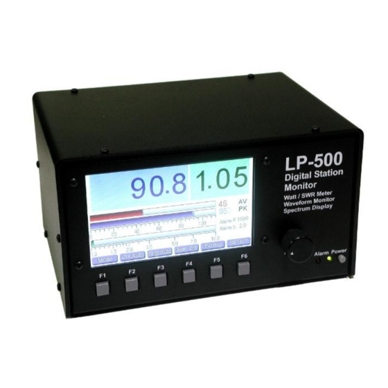
LP-500 / LP-700
User Guide v3.1
Connections...
Power: 12-16 VDC @ 800 mA maximum, center pin positive, 2.5mm. The cable either has a white stripe on the positive wire, or ridges on the negative
wire, depending on the cable supplied. The meter also has a protection diode to prevent damage in case of reverse polarity. If unsure, use multimeter to
check the wiring before plugging it into the meter. The meter has a built in replaceable 1A fuse on the PCB for protection. We recommend a well
regulated supply with a 1A to 1.5A rating. An alternative is to use the accessory 12VDC jack on the rig if it can handle the current. You can also use a
12VDC power distribution strip like RigRunner connected to the main station DC supply. Sharing the meter power with other devices when the supply is
marginal could result in ripple caused by the high current switching of the LED backlight between on and off states.
PTT: For older amplifiers, loop the PTT (send, amp keying) between your amplifier and rig through the LP-500 using RCA connectors. Two isolated pairs
of connectors are provided for connecting two amplifiers. Use either pair for either amplifier.
Test Tones: Audio output for built in test tones. 3.5mm mono. Connects to the MIC or LINE input of the rig. An attenuator will be needed in the case of
mic input, as well as galvanic isolation (transformer). Interfaces designed for a sound card based RTTY setup should work well for this. We plan to offer
an interface box for this type of connection in the future, which will allow hot-switching between the mic and LP-500, isolation and level balancing
between them. This will ensure that testing can be done at normal speech levels.
USB 2.0: Connects to computer using standard USB cable (Type A to Type B connectors). Used for flashing firmware and interfacing to LP-500 VM and
Utility programs. Can be connected to USB 2.0 or 3.0 jacks on PC. No special drivers are necessary since the standard Windows drivers are used.
Couplers: Connect to corresponding jacks on the coupler(s) using supplied or user provided CAT5/6 shielded Ethernet cables. See Fig.1 below.
1
Advertisement

Summary of Contents for TelePost LP500
- Page 1 LP-500 / LP-700 User Guide v3.1 Connections… Power: 12-16 VDC @ 800 mA maximum, center pin positive, 2.5mm. The cable either has a white stripe on the positive wire, or ridges on the negative wire, depending on the cable supplied. The meter also has a protection diode to prevent damage in case of reverse polarity. If unsure, use multimeter to check the wiring before plugging it into the meter.
- Page 2 Overview Fig.1. Shows installation with two couplers and PTT Alarm connections. The use of two couplers allows viewing of amplifier linearity with a trapezoidal display. PTT Alarm connections are optional and designed mainly for older amplifiers with no built in protection. The LP-500 Digital Station Monitor combines a state-of-the-art wattmeter and SWR meter with a task specific oscilloscope and spectrum analyzer, all using a large, bright color TFT display.
- Page 3 Power/SWR Mode… Power/SWR CH Auto Rng Auto AL Off Peak Hld Setup Waveform CH 1 Rng 5 AL On Average Normal Spectrum CH 2 Rng 10 (per channel) Tune CH 3 Rng 25 CH 4 Rng 50 Rng 100 Rng 250 Rng 500 Rng 1K Rng 2.5K...
- Page 4 Waveform / ‘Scope Mode… Power/SWR CH 1 Rng Auto SSB F 2 Tone+ Waveform CH 2 Rng 5 SSB S ½ Trap Wnoise+ CH 3 Rng 10 Scope Pnoise+ Spectrum CH 4 Rng 25 PSK F Wfm/Trap 2 Tone Rng 50 PSK S AM Mod WNoise...
- Page 5 Waveform / ‘Scope Mode, Continued… Descriptions below refer to these pictures and the one at the top of the previous page. ½ Trapezoid CW Envelope WFM / Trapezoid AM Modulation WFM / PWR Wfm Style Button: Selects the desired ‘scope display from these choices… Wfm: Standard ‘scope display…...
- Page 6 Spectrum Mode… Power/SWR CH 1 +65 dBm 2K Lin 2 Tone+ Waveform CH 2 +55 dBm 5K Lin Wnoise+ CH 3 10K Lin Pnoise+ Spectrum +45 dBm CH 4 2K Log 2 Tone 5K Log WNoise 10K Log Pnoise 400 Hz 1 kHz User 1 User 2...
- Page 7 Setup Mode… Power/SWR CH Auto Note: New option for Peak Response time Waveform CH 1 Spectrum CH 2 added after Alarm Pitch option. See below CH 3 for details CH 4 Mode Button: Changes mode CH Button: Selects among the 4 coupler channels. There are three parameters that are channel specific… Coupler, Pwr Alarm and SWR Alarm. The channel indicated next to each of these parameters is the one that is being adjusted.
- Page 8 Spectrum mode, as explained in the Spectrum Mode section. We will be posting some video tutorials on our LP-500 web page, www.telepostinc.com/lp500.html which will walk the user through various tests like amplifier linearity using the trapezoid display, frequency response tests using the white noise signal, two-tone IMD tests, etc.
- Page 9 Recommended Usage of the LP-500, Continued… Because the subcarrier must be stronger than the two test tones, this limits the peak power in the two tones, but still results in meaningful measurements on a relative basis at full power, so that the user can see the degradation of the IMD products depending on amplifier settings, or when comparing one amplifier to another.
- Page 10 For those with limited space for the LP-500, this provides a much larger display, and higher resolution. The VM is a free download, like all TelePost software, and very easy to set up. If the meter is plugged into a USB jack on the PC, starting the VM will automatically connect to it.
- Page 11 Using mikroBootloader to flash new firmware: Download the mikroBootloader software from our LP-500 web page, as well as the latest firmware. Unzip and install the software, then unzip the firmware file and save the resulting hex file to a convenient place where you might want to save future firmware versions as well. In this example, we’ll use LP500_v213.hex, and we’ll save it to the folder C:\Users\Shack\Downloads\LP-500_firmware\.
- Page 12 Using mikroBootloader to flash new firmware, Continued: Plug the LP-500 into a USB 2.0 port on the PC using the supplied USB cable. No special drivers are needed for the LP-500. It uses the standard Windows USB HID drivers and should be instantly recognized by the PC with the usual USB connect sound. Start the mikroBootloader program (Fig.
-
Page 13: Warranty
If failure occurs within the warranty period, return the LP-500 to TelePost Inc. at your shipping expense. The device will be repaired or replaced, at our option, without charge, and returned to you at our shipping expense. Repaired or replaced items are warranted for the remainder of the original warranty period. - Page 14 LP-500 & LP-700 are trademarks of TelePost Inc. Windows® is a registered trademark of Microsoft Corporation. Material in this document copyrighted ©2015, 2016 TelePost Inc. All rights reserved. All firmware and software used in the LP-500 & LP-700, VM and...
Need help?
Do you have a question about the LP500 and is the answer not in the manual?
Questions and answers