Table of Contents
Advertisement
SENTRY
Installation/Owners Manual
3
Year
Warranty
300 S / 300 D
®
High Quality Low Voltage
High Quality Low Voltage
Vehicular Swing Gate Opener
Vehicular Swing Gate Opener
Battery Powered
www.sentrygateopener.com
Solar or AC Charged
Designed to
open all types
of gates in all
kinds of places.
MADE IN THE USA
Advertisement
Table of Contents

Related Manuals for USAutomatic SENTRY 300 S


Summary of Contents for USAutomatic SENTRY 300 S
- Page 1 SENTRY 300 S / 300 D ® High Quality Low Voltage High Quality Low Voltage Vehicular Swing Gate Opener Vehicular Swing Gate Opener Battery Powered Solar or AC Charged Installation/Owners Manual Designed to open all types of gates in all kinds of places.
-
Page 2: Table Of Contents
TABLE OF CONTENTS INTRODUCTION About the Sentry ......................2 Safety Information ....................... 3 Sentry Parts Inventory ....................5 Sentry Hardware Inventory ..................6 General Tool Requirements ..................6 PREPARATION AND OVERVIEW Gate Qualifications/Applications .................. 7 Proper Gate Design ..................... 7 INSTALLATION 1. Mounting Site Review .................... 8 2. Determine Proper Brackets and Opening Method .......... -
Page 3: About The Sentry
The Sentry control board features high quality components and industry leading ideas such as auto resetting fuses for motor protection. The old automotive type fuse that frequently fail have been designed out of this controller to avoid the unnecessary expense of buying fuses. Another patent pending item designed into the control board is the on board potentiometers for adjusting stop limits. Many other features have been designed into the control board to ensure superior operation for years to come. Attention to detail and quality parts makes the Sentry Gate Opener the First High Quality Gate Opener for the Do It Yourself Installer. USAutomatic appreciates the fact you have recognized the quality of the Sentry gate opener for your installation and would appreciate your comments on how we are doing so that we may continue to build and design products in the future that work the way you want them to. PLEASE READ THE ENTIRE MANUAL CAREFULLY PRIOR TO INSTALLATION. In doing so, along with performing the installation in step-by-step order, you will achieve optimal results. Your Sentry control board was designed with a current sense safety feature and we strongly recommend other safety devices such as photo eyes to make each particular installation as safe as possible and reduce the risk of personal injury and/or property damage. -
Page 4: Safety Information
• Placards are installed, one on each side of the gate and visible in the gate area. • All contact sensors used for secondary entrapment safety devices and their wiring is installed in a manner which protects them from mechanical damage. • All non-Contact sensors used for secondary entrapment safety devices are located so that the signal from the transmitter to the receiver is not interfered with by adjacent structures. All exposed wiring must also be protected from mechanical damage. SECONDARY ENTRAPMENT DEVICES USAutomatic designs all control boards with secondary entrapment inputs. USAutomatic recommends that UL325 listed secondary safety devices be installed with all installations. USAutomatic recommends that these devices be connected after proper gate installation and operation has been verified. Then connect one device at a time to verify proper operation before installing the next device. Ensure that power is disconnected from the control board prior to wiring any accessory. - Page 5 15. THE ENTRANCE IS TO BE USED BY VEHICLES ONLY. Pedestrians must use a separate entrance. 16. All safety features required by UL 325 are incorporated in the capabilities of all USAutomatic Control boards and should be utilized, including but not limited to, safety edges, photo electric eyes, reverse sensing.
-
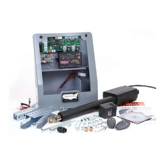
Page 6: Sentry Parts Inventory
SENTRY 300 Series part number 020320 PARTS INVENTORY Universal Actuator Linear Actuator Bracket Part # 510300 Part # 610400 1 per 1 per Transmitter Square Post Flush Plug N Go Harness Part # 030210 Mount Bracket Part # 630040 2 per Part # 610402 1 per 1 per 1/2” Cable Gland Transformer Round Post Flush Mount Bracket Part # 620022... -
Page 7: Sentry Hardware Inventory
HARDWARE INVENTORY 3/8 x 16 nylon lock nut 3/8 x 2 1/2” shoulder bolt Part # 610518 Part # 610512 5 per 3 per 1/4 x 20 nylon lock nut 3/8 x 16 x 8” carriage bolt Part # 610526 Part # 610510 2 per 2 per 3/8 USS flat washer Tap bolt Part # 610514 1/4 x 20 x 3 1/2”... -
Page 8: Gate Qualifications/Applications
PROPER GATE DESIGN IMPORTANT- A GATE OPENER CANNOT OVERCOME A POORLY DESIGNED GATE. Since the gate is a major component of the system, great care and concern must be given to the gate design. USAutomatic, LTD is not responsible for any damage to a gate in which the gate opener is installed. A poorly installed or misadjusted gate could be damaged. It is the responsibility of the installer to verify proper gate installation prior to opener installation. As a general rule, a gate, which is to be automatically operated, must be stronger and smoother than one operated manually. • Does the gate swing smoothly without binds or excessive resistance? • Swing gates should swing level and plumb to prevent the opener from having... -
Page 9: Installation
INSTALLATION Mounting Site Review Review the following items prior to installation and predetermine the solution to any problems which may exist: • Does sufficient space exist for mounting and future servicing of the opener and control box? • Which direction will the gate swing? • Will the gate opener pull the gate open to the inside (Pull to Open)? • Will the gate opener push the gate open to the outside (Push to Open)? • Where will the universal actuator bracket and gate bracket be secured at the hinge post and to the gate? • Where will the control box be mounted to support the weight of the battery and can it be located within 8 feet to prevent splicing of the actuator cable? • How will you charge the battery? Will it be AC or Solar charged? • How far away is the 110 VAC receptacles for the transformer? Transformer is supplied with 12 feet of cable, if extension is needed use Sentry Charge Cable Extension Kit (part #630050). See Appendix B (pg 42) for extension cable kit information and recommended wire size chart for extension distance needed. -
Page 10: Determine Proper Brackets And Opening Method
Determine Proper Brackets and Opening Method Mounting Brackets Determining which of the brackets will be needed for your installation. Square The Sentry gate opener is supplied with universal brackets to mount on round Post or square hinge post ranging in size from 2 3/8” to 6”. Some pieces may not be Bracket needed for your installation. The hinge post is the post your gate hinges are attached to. Follow the steps below to identify which of the included brackets will be needed for your installation. Round Is the hinge post round or square? Post Square post will use the “square post flush mount bracket”... -
Page 11: Push To Open Installation
Pull to Open Installation This installation method is the most common where the gate swings into the property/driveway. No matter which way you decide to install the actuator bracket and universal actuator bracket the pivot point below must be located in approximately this position for a pull to open installation. Gate Hinge Center (pivot point) Push to Open Installation This installation method is common where the driveway slopes up entering the property and gate must swing out to avoid interference. This type of installation places the actuator bracket and linear actuator into the drive area slightly. Another installation method would be to install as a Pull to Open and place linear actuator on outside of property. Push to open installation can be achieved by installing universal actuator bracket and actuator bracket as shown in figure below. Dimensions for this install method are 7” and 4” from hinge center. Universal actuator bracket hole pattern allows for the actuator bracket to be installed as shown in this location only. Establish enough offset in the rear actuator pivot point to allow the gate to close from the open position. IMPORTANT: If Installation is Push to Open, control switch #2 “operating direction reverse” must be turned “ON”. -
Page 12: Attaching Universal Actuator Bracket To Hinge Post Or Post Being Used
Attach Universal Actuator Bracket to hinge post or post being used Mounting hardware needed: • two 3/8” x 16 x 8” carriage bolts • two 3/8” USS flat washers • two 3/8” nylon lock nuts The universal actuator bracket can be installed in many different ways to accommodate your gate opener installation. The pictures here are for reference and your installation might differ. Universal actuator bracket must be securely installed. Drilling through the post is the strongest method. NOTE: In all cases, the universal actuator bracket should be aligned level with a horizontal gate section. 1. -
Page 13: Attach Actuator Bracket To Universal Actuator Bracket
Attach Actuator Bracket to Universal Actuator Bracket Pivot Point Predrilled The actuator bracket has a 3/8” pre drilled hole that the linear actuator will mount to. This is the pivot point for the linear actuator. In all cases, the Hole universal actuator bracket should be aligned level with a horizontal gate section. (see Mounting Site Review) For a Pull to Open installation - the pre-drilled hole must be located 5” Actuator behind the gate hinge and 8” to the inside of the property. Bracket For a Push to Open installation the pre-drilled hole must be located 7” in front of the gate hinge and 4” to the drive side of the hinge. These dimensions are measured from the center of the gate hinge (pivot point). Hardware needed: • two 3/8” x 2 1/2” shoulder bolts • two 3/8” USS flat washers • two 3/8 nylon lock nuts. -
Page 14: Install Gate Bracket To Linear Actuator
Install Gate Bracket to Linear Actuator Install manual release pin, gate bracket and manual release clip to linear actuator extension rod end. Install Gate Bracket to Gate (Pull to Open Only) To determine where the gate bracket will be installed follow these steps: The linear actuator should be connected to the actuator bracket at this point. NOTE - The linear actuator was shipped from the factory set to the fully retracted position. -
Page 15: Install Sentry Control Box
3. Attach the 4 #12 hex head self tapping metal screws. 4. Mount the control box on the screws. Verify the structure the control box is mounted on is sufficient enough to hold the control box and battery securely. Splicing for Sentry 300 S Linear Actuator Cable (if needed) The Sentry linear actuator comes with 8 feet of cable. Avoid splicing this cable if possible. If the control box must be located in such a way that splicing is required follow the guidelines below to avoid problems. Determine the length of additional linear actuator cable needed and either build it yourself or visit www.sentrygateopener. -
Page 16: Sentry Plug N Go Harness
Sentry Plug N Go Harness The Plug N Go Harness comes preinstalled and should be plugged into the bottom of the charge controller. Plug is color coded. Red connects to positive battery post and Black connects to negative battery post. Once connected, place harness into wire compartment to prepare for battery installation. Charge controller connector 15 amp fuse 1/4” Ring terminal for battery Gate 1 and Gate 2 linear Red connects to positive battery post actuator power plugs Black connects to negative battery post Install Battery BATTERY REQUIRED FOR OPERATION (Battery not included) Recommended battery type - 12-volt, Group U-1; sealed... -
Page 17: Install Charging System (Ac Or Solar)
Install Charging System - AC or Solar For AC Charge Option - Install Transformer Supplied with opener The USAutomatic transformer (PN520008) supplied is a low voltage UL approved transformer for this type of application. The transformer is equipped with a DC plug for easy connection to the charge controller and can easily provide 575 cycles of operation a day without decreasing the battery charge. In the event AC power goes out the opener will operate for weeks on the battery (if cycles per day are below 20) before needing service. Accessories connected to the opener are critical. Always use Solar Friendly accessories to help avoid premature battery failure in cases of power outages. TRANSFORMER MUST NOT GET WET. 1. Loosen cable gland nut and route the cable from the charge device into the control box (see figure). Ensure that DC plug can reach the charge controller “Power In” connector. 2. Tighten cable gland nut to hold cable in place. 3. Connect the transformer to an approved electrical receptacle. Cable Gland NOTE: The 110 VAC receptacles should be installed by a qualified electrician, per local building codes. -
Page 18: Connect Charge Device To Charge Controller
Charge Device plugs in here Connect Charge Device to Charge Controller (Transformer or Solar Panel Kit) The Sentry gate opener charge controller accepts inputs from either the supplied AC transformer or the optional solar panel. The transformer and solar panel come with a DC plug for easy installation. Once the charge device is selected and installed connect the DC plug into the charge controller “Power In” located in the upper right corner of the charge controller. If charge device cable needs to be extended to reach the charge controller see appendix B of this manual. Charge Controller Operation Check Once the charge device is plugged into the charge controller verify the following: Transformer: 1. -
Page 19: Install Linear Actuator Cable
Install Linear Actuator Cable With the control box installed route the linear actuator cable into the bottom of the control box using the 1 1/4” hole in the rear bottom. Slide the hole plug that is installed on the linear actuator cable into the control box hole and snap in place. If cable length is excessive, coil up and place in the wire compartment of control box. Ensure the length allows for connection to the Sentry control board Gate 1 connector. Sentry Plug N Go Harness Final Installation At this point verify the following items have been completed: Linear actuator installation is complete. Control box is securely installed. Plug N Go harness is connected to the charge controller. Plug N Go harness is connected to the battery. Battery is installed in the battery compartment of control box. Charge device cable is routed into control box and connected to the charge controller. Linear actuator cable is routed into control box. Verify the above items have been completed correctly before continuing. If necessary, correct before proceeding. -
Page 20: Sensitivity Adjustments And Entrapment Alarm
Sentry Control Board Information The Sentry control board is capable of operating two gates. If your installation is a single gate you can operate the gate on the Gate 1 or Gate 2 connector. Set control switch “ON” for the connector being used. The Sentry gate opener was shipped with the receiver and entrapment siren already connected to the control board; these connections are plugs that can easily be disconnected. Sentry Control Board Sensitivity Adjustments and Entrapment Alarm Gate 1 and Gate 2 sensitivity adjustments are located on the left edge of the control board. Sensitivity is the primary safety control designed into the control board. The adjustment dials control the amount of force the gate can apply to an object before the gate will stop and reverse direction. If the gate senses an obstruction it will reverse direction. If it senses a second obstruction before reaching the fully open or closed position the gate will shut down. The entrapment alarm which is preinstalled in the control box will sound. Entrapment alarm will continue for 5 minutes then shut off. The entrapment alarm can be reset by pressing the “Reset” button on the control board. Sensitivity Adjustments If two obstructions were detected and control board has shut down, the “Reset” button will have to be pressed to re-activate the opener. -
Page 21: Adjusting Gate 1 And Gate 2 Sensitivity
Adjusting Gate 1 and Gate 2 Sensitivity Sensitivity factory setting is on position 5. This setting will work with most gates. Adjust so that when gate is stopped by an object, it stops and reverses direction. If gate stops and reverses for no obvious reason then increase force by slightly adjusting clockwise. If force is set too sensitive false sensing may be observed. IMPORTANT: If adjusting for a single gate, once adjustment for that gate is set, also set the other sensitivity adjustment to the same setting. Adjusting both Gate 1 and Gate 2 sensitivity adjustments to the same setting for a single gate installation will prevent the possibility of false trigger and gate reversal. -
Page 22: Operating Gate For The First Time
J2 Terminal (Accessory Wiring) Accessories wire to the J2 connector. Insert wire and tighten screw. J2 pin functions are as follows: J2 pin 1 - +12 VDC output for any accessory power needed (80ma max). J2 Terminal J2 pin 2 - Ground connection for any accessory item. J2 pin 3 - Push Button input J2 pin 4 - Monitored contact edge input N/O J2 pin 5 - Safety Reversing input (Photo Eye N/O input) J2 pin 6 - Photo Eye Power output (+12 VDC only) connect photo eye power lead here. J2 pin 7 - Solenoid Lock Power output (+12 VDC only) connect solenoid lock power lead here. J2 pin 8 - Monitored Photo Eye - N/C J2 pin 9 - Open Input / Exit Sensor - N/O Control Switch Functions Switch 1 A uto close enable – Turns on the auto close feature. Gate will close from any position. DO NOT turn this feature on unless safety devices are installed (see page 29) for details. -
Page 23: Making Final Adjustments
Making Final Adjustments Once the gate has traveled to the stop position adjust the Gate 1 “Extend Limit More or Less” adjustment dial located on the control board. Turn the adjustment slightly clockwise to close gate more, cycle gate and repeat until close position is correct. If gate is adjusted past the desired closed position turn the adjustment counter clockwise slightly. Then cycle the gate to verify close position is correct. Install Safety Signs Mount the 2 included safety signs on inside and outside of the gate area so they are clearly visible. Programming Transmitter and Receiver (model 433DSR2LC): Operating frequency 433.92 MHz. Receiver can store up to 42 unique transmitter dipswitch code settings. Transmitter Setup: (It is recommended that the dipswitch code be changed from the default factory setting) Battery 1. Open the battery compartment door and locate the dipswitches. Compartment Door 2. Change the dipswitches to the settings you prefer, record for future reference... - Page 24 Programming Transmitter and Receiver (cont) 2. Press and hold the right transmitter button down. Red light on transmitter should be on. 3. Press the P2 push-button until the green LD light comes on. 4. Release both buttons. Transmitter right button to receiver programming is complete. Receiver Programming - Latch Open Mode: Relay P2 programming from momentary to latching mode (to hold gate open) 1. Press the P2 push-button until the green LD light comes on, then release. Green LD light should be steady. 2. While the green LD light is on, push the P1 push-button down and release. Green LD light should be flashing. Latching mode is set. Verifying Receiver P2 relay is programmed to latching mode: 1. Press the P2 push-button until the green LD light comes on, then release. 2. Green LD light should be flashing. If green LD light is steady, redo the Receiver Programming section above.
-
Page 25: Entrapment Zones
ENTRAPMENT ZONES Zone 1 The leading edge of the gate & catch post. Zone 2 Area between the gate and hinge post. Zone 3 The arc of the gate or gate path. Zone 4 T he space between the gate when open and any obstruction such as fence, wall, landscaping, etc. Zone 5 The point where two bi-parting gates come together when closing. (Not shown below) Every installation is unique and it is the installer’s responsibility to recognize and remedy all safety concerns. Please consult a qualified dealer or the factory for a complete explanation of the remedies shown above and additional tips pertaining to your installation. PERIODIC SERVICE All gate operators require periodic checking and adjustments of the control mechanism for force (load), speed and sensitivity. All accessories and secondary safety devices must be checked. Secondary safety devices need to be checked at least once a month for proper operation. Periodic checking is also advised for the following: 1. Battery terminals for corrosion, clean with baking soda solution. 2. Hinges and pivot points need to be greased. 3. Mounting bolts for correct tightness. 4. Inspect weld points for cracks or other defects. 5. Inspect wiring for cuts, nicks or other defects. 6. Inspect hinge post to ensure it is not moving or twisting. 7. -
Page 26: Sentry 300 D Gate 2 Installation
Sentry 300 D Gate 2 Installation PN #020325 PARTS INVENTORY Universal Actuator Bracket Linear Actuator Part # 610400 Part # 510300 1 per 1 per NOTE: Arrow installs toward drive. 50 Ft 5 Conductor 1/4 x 20 x 2 1/2” Extension Cable Tap Bolt Square Post Flush Part # 630035 Part # 610520 Mount Bracket... - Page 27 The Gate 2 kit contains linear actuator with 1 1/4” hole plug, 50 feet of 5 conductor cable, wire nuts, junction box and mounting hardware. The Sentry control box is equipped with two knock outs for the gate 2 linear actuator cable. One knock out is 1 1/4” and is intended for non conduit installation (not advised). The other knock out is 7/8” and designed for 1/2” conduit fitting for conduit installation (recommended). (see figure) If conduit is being installed knock out 7/8” hole. If conduit is not being installed knock out 1 1/4” hole. Remove the knock out that is right for your installation. Control Box Knock Outs Installing Gate 2 Linear Actuator 1. Install Gate 2 linear actuator using the procedure described for the Gate 1 actuator. The linear actuator for Gate 2 comes with an 8’ cable that must be cut and spliced in the following manner once linear actuator is installed. Once Actuator is installed: 1.
- Page 28 CAUTION: To reduce the risk of injury, USAutomatic strongly recommends the installation of additional safety devices such as Photo Eye Sensors and Safety Edges. Consult an authorized installing dealer or www.Sentrygateopener.com for a complete explanation of options and see...
-
Page 29: Accessories
Accessories Sentry Garage Door Receiver Part Number 030209 The receiver provided with the Sentry gate opener operates at 433.92 MHZ and might or might not be compatible with your garage door. If receiver frequency is not compatible the optional “Sentry Garage Door Receiver kit” can be easily installed in the garage. The kit contains receiver, transformer and a wire harness that easily installs to the existing garage door. One receiver will be needed for each garage door. All existing transmitters used for garage door will continue to operate. They are not being disconnected. Mounting hardware included. To program open receiver box cover. Place small screw driver in slot to open. Press the learn button. Then press the transmitter button that will be used to open the garage. See garage opener for connecting the 2 wires supplied. If needed, 4 button transmitters are available at www.sentrygateopener.com part number 030212. CAUTION: DOOR WILL OPERATE WHEN RECEIVER IS PROGRAMMED IF SIGNAL WIRES ARE ATTATCHED. KEEP HANDS CLEAR OF MOVING PARTS TO AVOID INJURY Sentry Push to Operate Wireless (Solar friendly device) Part Number 050510 The Push to Operate transmitter is designed for outdoor wireless installation. Install to allow operation of the gate or garage by simply pressing the pad. The button is a pressure sensitive pad. Press the pad an audible tone is generated. Programming is identical to transmitter programming. Installation hardware is included. 7 Day Timer (Solar friendly device) Part Number 550015 The optional 7 day timer can be used to open the gate at a preset time and if the auto close feature of the gate operator is being used the gate can then close automatically at a preset time. The timer is supplied with 3 spade terminals for easy connection. - Page 30 Sentry Photo Eye (Send and receive) Part Number 550012 The photo eye is a secondary safety device. It produces a beam between the 2 units. When the beam is broken it will keep the gate from closing. It requires wires to be connected to both units (20 gauge) for operation. Typically a swing gate needs two sets of photo eyes for the best area protection (see figure below). One set of photo eyes pointing across the drive on the Transmitter Receiver outside of the hinge post (A). The second set mounted across the drive at the point where the gate is fully opened (B). The photo eye must be installed where the gate does not break the beam. The primary unit (Receiver) should be installed close to the control box. It requires 4 wires to be installed from the unit to the control box. The second unit (Transmitter) should be installed on the opposite side of the drive. It requires 2 wires to be installed from the unit to the control box. The two units must face each other to establish the beam (maximum distance 40 feet). Photo Eye Installation / Wiring Select a proper installation site, where the transmitter and the receiver can be along the same line and at the same height. Remove the cover from both units. Attach back plate to the installation site using mounting holes in back plate. If conduit is being used (recommended) knockouts are provided in the unit for 1/2”conduit fitting. Install wires into unit and strip 1/4” of insulation to prepare for wiring connections. Connect both conduits to a weather tight junction box. Then connect an additional conduit between the junction box and Sentry control box. The Sentry control box has knockouts for the conduit. Verify which knockout is available for the photo eye conduit. Pull wire into Sentry control box wire compartment. Transmitter wiring – 2 wires will be connected to the transmitter. First wire connects to ground (“GND”) terminal and the second wire connects to “+12V” terminal. Receiver wiring – 4 wires will be connected to the receiver. First wire connects to “+12V” terminal, second wire connects to “NO” terminal, third wire connects to the “GND” terminal and the fourth wire connects to the “COM” terminal.
- Page 31 Electric Gate Lock Part Number 070510 The USAutomatic Electric Gate Lock works with an automatic gate operator to securely lock the gate into position without having to step out of a vehicle. The USAutomatic Electric Gate Lock is wired into the gate operator control box, and when an input device such as a transmitter or keypad is used to open the gate, the USAutomatic Electric Gate Lock disengages. The gate will then swing open. When closing the gate, the gate retracts and the gate lock automatically engages to secure the gate in the closed position. • R ugged steel housing and catch assembly • S trike pin removable for emergency release • 12 vdc operating voltage • B olt-on Installation • M ounting hardware included • L ow amperage, rack and pinion driven • S pring loaded self-latching locking mechanism...
- Page 32 Programming Your Wireless Keypad 050520 or 050550 050500 (plastic) (metal) PUK code PUK code ___________ ___________ Terms to Understand Access Code – The 2 to 5-digit code used to open the gate (24 unique codes are possible). If access code is less than 5 digits it requires the # sign after code is entered. Example: “2 #.” If code is 5 digits the # sign is not required. Metal keypad uses A or B in place of * and #. ACCESS CODE CAN NOT BE THE SAME AS THE MASTER PASSWORD. Master Password – The 5-digit code used to access programming features. Factory default is “11111”. This should be changed for security reasons. NOT USED TO OPEN GATE AND CAN NOT BE THE SAME AS THE ACCESS CODE.
- Page 33 Create Communication with Receiver: *for P1 (relay 1) access code: Receiver 1. Carry keypad to receiver location for programming. P1 Button 2. E nter Access Code for P1 (relay 1) on the keypad and continue to press the last key entered (red light blinks). P2 Button 3. P ress P1 (learn button) on the receiver until LD (green light) comes on and relay clicks. Create Communication with Receiver: *for P2 (relay 2) access code: 1. Carry keypad to receiver location for programming. 2. E nter Access Code for P2 (relay 2) on the keypad and continue to press the last key entered (red light blinks). 3. Press P2 (learn button) on the receiver until LD (green light) comes on and relay clicks. Programming New Master Password: Once created record here for reference __________ NOTE: The Master Password is NOT an access code.
- Page 34 5. Reenter the Access Code to be deleted. 6. Press the “7” key. If correct, 2 short beeps (if 1 long beep is heard, start over with step 1). Deleting All Access Codes: 1. Enter the Master Password. 2. Press the “7” key. If correct, 2 short beeps (if 1 long beep is heard, start over with step 1). 3. Reenter the Master Password. 4.
-
Page 35: Troubleshooting
Troubleshooting Terms and Definitions Control board - See page 19 Receiver - See page 22 Transmitter - Hand held unit with 2 buttons, used to operate the gate, sends signal to receiver when button is pressed see page 22. Linear Actuator - Connected to gate and hinge post, contains the motor, gearbox. Connector - Control board has Six, two white 8-pin connectors (X1 and X2) are used to connect linear a ctuator to control board and one 7-pin connector (J2) (located bottom center of control board) for accessory wiring, two 2 pin header (J3, J4) for entrapment siren & external “Reset” and one four pin header (J1) for receiver. Push Button - Two are located on the control board. “Open/Close command” used to operate the gate a nd the “Reset” used to reset the control board after current sensing twice before a limit is reached see page 21. Control Switches - Used to turn “ON” or “OFF” specific control board functions see page 21. Sensitivity adjustments - Located on the control board see page 19. These adjustments are t he primary safety feature. If the gate comes in contact with an object it will stop and reverse. These adjustments control the amount of force applied to an object before reversing the gate. Charge Controller - Located inside the control box see page 17. This is the battery charger. T he input power for this device can be either from the transformer (supplied) or the Sentry Solar Panel (Part #520015). Transformer - This device connects to a 110 VAC electrical outlet and converts it to a low AC voltage that can be connected to the charge controller to provide continuous charging of the battery. Retract and Extend Limit - This refers to the fully open or closed position and are adjusted on the control board see page 20. - Page 36 Problems Gate 1 or Gate 2 will not operate. Single gate installation. Gate 1 or Gate 2 will not operate. Dual gate installation. Gate 1 and Gate 2 will not operate. Dual gate installation. Single or Dual gate installation opens or closes very slow. Single or Dual gate installation will not automatically close.
- Page 37 2. Gate 1 or Gate 2 will 1. These instructions are for the failure of one gate to operate in a dual gate installation. not operate. Dual gate Installation 2. Identify the gate that will not work and check the control switch for that gate and verify that it is turned “ON”. 3. Swap the Gate 1 and Gate 2 linear actuator connectors on the control board. If problem moves to other gate then the control board is bad. 4. If problem remains in the same gate then the problem is either a wire problem or linear actuator problem. Since it is a possible wire problem we need to check the following: A. Wire harness for cuts, nicks or bad splices if splice exist. B. If gate with problem is the gate located on the other side of drive from control box (Gate 2) the cable under the drive needs to be verified good. This is done by using a voltmeter and going to the junction box located below the Gate 2 linear actuator. Locate the red wire with white stripe and the black wire with white stripe and then operate the gate and check voltage on these two wires (expect 12 VDC). C. If voltage is present when gate should be operating then the problem is most likely the linear actuator. D. If voltage is not present when gate should be operating then move back to the control box side and check voltage on same two wires located in the wire compartment. E. If voltage is present on the control box side of drive then the cable in the ground must be damaged.
- Page 38 4. Gate 1 or Gate 2 (Gate 1 When the gate is running slow, the reason is low power. The Sentry charge controller does not output any voltage or current and Gate 2 if dual gate) when disconnected from the battery, you cannot check the operating speed has charge controller by disconnecting from battery and measuring slowed down output voltage. To check charge controller output, disconnect from battery, measure battery voltage and note. Reconnect charger and monitor battery voltage it should rise above the battery voltage noted above. Two things need to be considered. 1. Battery condition (replace or charge) 2. the 1/4” ring terminals located on the Plug N Go harness which are connected to the battery. The ring terminals can become corroded and need replacing over time. Remove battery and have it load tested at a battery shop. Replace if bad. 5. Single or Dual gate If control switch number 1 is turned “ON”...
- Page 39 6. Single or dual gate 1. In this condition the open time can be controlled by adjusting the auto close timer adjustment. installation gate auto opens instead of auto 2. If installed in the pull to open configuration then control switch number 2 should be turned “OFF” verify it is. If installed in the closing push to open configuration verify switch is turned “ON”. 3. Gate is trying to close too far. Readjust close limit adjust for gate 1 or gate 2 to the correct stop position. 4. If time before auto opening cannot be adjusted and occurs in a couple of seconds after closing then the close limit adjustment of one or both gates is misadjusted. The feature that is causing the gate to open is the current sense circuit on the control board. The gate is trying to close farther than possible and it has traveled to the full extent of the linear actuator. Verify that linear actuator harness has no cuts or nicks. 5. Verify correct installation of the universal actuator bracket. Possible cause is incorrect installation of the gate bracket or linear actuator bracket. Verify and correct as required. 7. Gate begins to open or 1.
- Page 40 9. Transmitter (remote 1. Remove the J1 connector from the control board and then reconnect, press transmitter button to verify operation. control) will not operate the gate 2. Open the control box and press the transmitter button to operate the gate, listen closely for a clicking sound coming from the receiver. Click should be heard when the transmitter button is pressed if transmitter and receiver programming is correct and they are working correctly a sound should be heard. 3. If click was not heard verify that “Programming transmitter and Receiver” steps on page 22 have been completed. 4. If clicking sound was not heard, verify that transmitter battery is good, replace if necessary. 5. If click was not heard verify that transmitter dip switches were not changed after initial programming on page 22, if so then reprogram transmitter to receiver following steps on page 22 or set back to original setting recorded on page 22. 6. If click was not heard verify that receiver has power applied to it by pressing the P1 button on receiver and holding down until green light comes “ON” then release P1. If light comes “ON” then power to unit is correct. If light does not come “ON” verify that connector J1 is connected to control board correctly. If light does not come “ON” and power to receiver is good then receiver is possibly bad. 7. If clicking sound was heard then the problem might possibly be the control board. Verify control board is not the problem.
- Page 41 10. Photo-eye or other 1. The first thing to check is the accessory wiring. See accessory wiring information on page 21. safety accessory will not reverse the gate 2. Accessory being used should be wired with the N/O wire connected to J2 pin 5 on the Sentry control board. when closing or hold the gate open 3. Verify the control switch “Operating Direction Reverse” switch is set in the correct position, Pull to Open switch is OFF. 4. Connect a wire to J2.5 then start the gate closing and then touch the free end of this wire to J2.2. Gate should stop and reverse. If gate reverses then the control board is working correctly and the accessory is the problem. 5. If gate does not stop and reverse, the control board is the problem. 11. Transmitter operating 1. Replace the batteries in the transmitter. range seems short 2.
-
Page 42: Appendix
GATE CYCLES PER DAY SOLAR CHARGED SYSTEM (Optional Solar Kit PN #520015) Solar charged systems should not exceed the cycles listed in the chart below. These numbers are based on a single 5 watt solar panel installation. If additional panels are installed additional cycles will be available. Model Type REGION 1 REGION 2 REGION 3 Sentry 300 S single gate 8 cycles per day 27 cycles per day 50 cycles per day Sentry 300 D dual gate 5 cycles per day 13 cycles per day 23 cycles per day Region 1 covers the area of the country receiving the least amount of solar radiation. On average the amount of charge time is 1.5 hours in region 1, 3 hours in region 2 and 5 hours in region 3. - Page 43 Extending Charge Device Location (AC or Solar) If charge device cable needs to be extended to reach the charge controller use “Sentry Charge Cable Extension Kit” Part Number 630050 (see figure). The kit contains junction box, DC plug pigtails and wire nuts. Use charts below to determine wire size needed for the distance to be extended. The cable must be a 2 conductor cable, stranded wire recommended. Do not modify the transformer or solar panel cable, this will void the product warranty. Sentry Charge Cable Extension Kit Part Number 630050 1.
- Page 44 CHARGE CONTROLLER L.E.D. DESCRIPTIONS EXTERNAL POWER ADAPTOR - Illuminates continuously while power from A.C. Power Supply Adaptor is sensed. SOLAR PANEL - Illuminates continuously while power from Solar Panel is sensed. DETECTION - If illuminated for longer than 3 seconds check connection on battery. CHARGING - Continuous or flashing indicates charging. CHARGED - On continuously when input power is present and battery fully charged. Flashes when battery capacity is low. SYSTEM ERROR - If flashing, the charger has entered Failure Mode. Disconnecting power will r eset charger, but if source of failure is not corrected, Failure Mode will occur again.- refer to the following Table to Decode the Error Type: L.E.D.s (First 4 L.E.D.s from Left) Wrong Battery Voltage Flash Reverse Battery Connection Flash Thermal Runaway Condition Flash Charge Time Monitor - 1 Flash Flash Charge Time Monitor - 2...
- Page 45 POSSIBLE REMEDIES TO CHARGE CONTROLLER ‘FAILURES’ WRONG BATTERY VOLTAGE Charger connected to a 24v battery. Reconnect to a battery rated at 12Vdc. REVERSE BATTERY Check and correct any reverse battery. CONNECTION THERMAL RUNAWAY Old Battery - cells, inside battery, age differently. During CONDITION c harging, and over the course of many years of operation, OR, many battery discharges to levels beyond 100% discharged, this error may occur and the battery(s) may have to be replaced. CHARGE TIME MONITOR – Battery pack took too long to complete its charge. Possible 1 and 2 causes include a load (gate cycling repeatedly for a long period of time) during charging or the battery pack is too large (Many batteries connected in a parallel circuit). Apply the following formula to determine if the Timer may run out due to a large battery: Charge Time = Battery Capacity (AH) x 1.25 Calculated Charge Time must be less than approximately 108hrs.
-
Page 46: Warranty
Sentry 300 WARRANTY AND REPAIR INFORMATION If your Sentry Automatic Gate Opener is not operating properly, please follow all troubleshooting procedures in the Troubleshooting Guide in this Manual. If you are unable to solve the problem, call USAUTOMATIC at 1-866-711-0001, or visit our web site at www.sentrygateopener.com. We will help with troubleshooting and arrange repair or replacement, if needed. When you call, please have the model and serial number of the Sentry Automatic Gate Opener. CONSUMER AFTER INSTALL: Return the enclosed warranty registration or register online at www.sentrygateopener.com. Retain your sales receipt for proof of purchase and date purchased. NOTE: PRODUCT MUST BE REGISTERED WITHIN 30 DAYS OF PURCHASE TO BE COVERED. 3 YEAR WARRANTY Warranty Coverage If your Sentry Gate Opener, also referred to as the “Product”, does not work properly due to a defect in materials or workmanship, USAutomatic will, for the length of 3 years, which begins on the date of the original purchase, at its option either (a) repair your Product with new or refurbished parts, or (b) replace it with a new or refurbished Product. .The repair or replacement of the Product will be made free of charge including parts, shop labor, and return to customer shipping and handling. In all cases, the decision to repair or replace will be made by USAutomatic. Included shop labor does not apply to removal or installation of the Product on purchaser’s home or premises. Product must be shipped, at purchaser’s expense, to USAutomatic during the applicable Warranty period. The Warranty excludes both parts and labor for batteries, and cosmetic parts such as product housing and paint finishes. The Warranty only applies to Products purchased in the United States and is extended only to the original purchaser of a new product that was not sold “as is”. - Page 47 BE CHARGED FOR THE REPAIR OF ANY PRODUCT OR PRODUCT PART RECEIVED WITHOUT SUCH PROOF OF PURCHASE OR FOR REPAIRS REQUESTED OUTSIDE OF THE APPLICABLE WARRANTY PERIOD. Warranty Limitations and Exclusions This Limited Warranty ONLY COVERS failure due to defects in materials or workmanship, and DOES NOT COVER normal wear and tear or cosmetic damage, The Warranty ALSO DOES NOT COVER damages which occurred in shipment , or failures which are caused by products not supplied by USAutomatic, or failures which result from accidents, misuse, abuse, neglect, mishandling, misapplication, or alterations, faulty installation, connection to an improper power source, set-up adjustments, misadjustment of controls, improper maintenance, power line surges, damage from acts of God such as lightning, wind, fire, flood or insects, introduction of sand, humidity or liquids, commercial or rental use or service by anyone other than an Authorized Sentry Repair Center. THERE ARE NO EXPRESS WARRANTIES EXCEPT AS STATED UNDER “WARRANTY COVERAGE”. USAUTOMATIC IS NOT LIABLE FOR INCIDENTAL OR CONSEQUENTIAL DAMAGES RESULTING FROM THE USE OF THE PRODUCT, OR ARISING OUT OF ANY BREACH OF THIS LIMITED WARRANTY. (As examples, this excludes damages for lost time, lost calls or...
- Page 48 © USAutomatic, LTD, 2015 rev. B All rights reserved. No part of this may be reproduced by any means without the expressed written consent of the publisher.
Need help?
Do you have a question about the SENTRY 300 S and is the answer not in the manual?
Questions and answers