Table of Contents
Advertisement
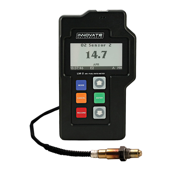
LM-2
Digital Air/Fuel Ratio Meter
User Manual
This manual assumes that firmware version 1.18 or later is installed.
Warning!
It is extremely important to avoid hot-plugging sensor connections. Do
not connect or disconnect the sensor connectors while the unit is
powered ON.
The Oxygen Sensor used in this device gets very hot in operation.
Do not touch the hot sensor. Do not let a hot sensor touch a
combustible surface. Do not use the sensor with or near flammable
liquids or gases. Failure to heed these warnings may result in severe
burns, explosions or fires.
When installed in the exhaust, the oxygen sensor MUST be connected
and operating with the LM-2 whenever the car is running. An un-
powered oxygen sensor will be quickly damaged when exposed to hot
exhaust gases.
1
11-0122B
Advertisement
Table of Contents

Related Manuals for Innovate LM-2

Summary of Contents for Innovate LM-2
- Page 1 When installed in the exhaust, the oxygen sensor MUST be connected and operating with the LM-2 whenever the car is running. An un- powered oxygen sensor will be quickly damaged when exposed to hot exhaust gases.
-
Page 2: Table Of Contents
OBD-II ....................11 Selecting OBD-II Channels on the LM-2 .......... 11 Check Vehicle Trouble Codes on the LM-2 ........12 Clear Vehicle Trouble Codes on the LM-2 ........12 Selecting Channels with the LM Programmer software ....12 ... - Page 3 LM-2 The LM-2 is a single or dual channel wideband controller with a built-in OBD II scan tool, RPM input, four analog inputs, MTS serial I/O, SD memory card recording and two analog outputs. Front MODE Press once to cycle through channel display screens.
- Page 4 Left Inductive Clamp MTS Serial IN MTS Serial OUT SD Memory Card USB Connector Bottom Analog Cable Power OBD-II Connector Sensor Port # 2 Sensor Port # 1 (Enabled with the Dual Channel version) 11-0122B...
-
Page 5: Main Screen
Main Screen There are 3 different screen view options: one channel, two channels, and four channels. These can be cycled by momentarily pressing the MODE button. The type of channels being displayed can be changed by using the UP and DOWN arrows. One Channel Two Channels Four Channels... - Page 6 - Error, Check Appendix E for error code meanings and trouble shooting tips Note: If the LM-2 is a single channel model, the second indication will be blank, not an error code. The next indicator, “R”, will appear when a) RPM is selected for logging/use (see menus) and b) an RPM signal is detected.
-
Page 7: Configuration Menu Screen
The blinking “M” indicates that MTS serial data is being generated. This will blink at the relative MTS packet rate (for comparison with the O indicator). If the unit is not the “head” unit, then this will only blink when packets are being received via the Serial In connector. -
Page 8: Air/Fuel Ratio Setup
When installed in the exhaust, the oxygen sensor must be connected to a powered, functional LM-2 (no error codes) whenever the engine is running. An un-powered sensor will be damaged in a short period of time when exposed to exhaust gas. -
Page 9: Sensor Calibration
The calibration procedure requires that the oxygen sensor be in free air, this means removed from the exhaust system completely. 1. With the LM-2 powered off, connect the oxygen sensor to the sensor cable and the other end to the sensor input on the LM-2. -
Page 10: Calibration Schedule
3. The sensor(s) will start warming up. The LM-2 will display WXX, where XX is the percentage of temperature reached. Notice the status bar displaying a ‘W’. 4. Once the unit stops indicating the sensor is warming up, it is time to trigger the calibration. -
Page 11: Obd-Ii
When the LM-2 first establishes the connection to the vehicle’s ECU it will query the list of available channels, the LM-2 will then only allow a selection from this list. When moving the LM-2 from vehicle to vehicle is it important to reset the channel count to 1 and set the protocol to ‘Automatic’. -
Page 12: Check Vehicle Trouble Codes On The Lm-2
5. Select Clear DTC Codes and press the ENTER button. Selecting Channels with the LM Programmer software 1. Connect the LM-2 to your computer with the provided USB cable. Connect the OBD-II cable to vehicle’s OBD-II port and the other end to the LM-2. -
Page 13: Check And Clear Vehicle Trouble Codes With Lm Programmer
6. Hit the ‘Program’ button to send the configuration. Check and Clear Vehicle Trouble Codes with LM Programmer 1. Connect the LM-2 to your computer with the provided USB cable. 2. Connect the OBD-II cable to vehicle’s OBD-II port and the other end to the LM-2. -
Page 14: Obd Ii Connection Diagnostic Trace
RPM – (Blue) RPM Input The LM-2 has a direct tach signal input signal. This input can be used to feed a signal from the negative lead of a coil, ECU, negative lead of an injector, or ignition box (i.e. MSD 6AL). This tach signal can be feed to the RPM + (Black/White) wire. -
Page 15: Enable/Disable Rpm
Enable/Disable RPM Enabling the RPM channel will allow you to display the channel on the LM-2 and log it on the SD memory card. Disabling the channel will do the exact opposite. 1. Press and hold the MODE button to go into the Configuration Menu Screen. -
Page 16: Attenuating A Tach Signal
Wiring 1. Connect the tach signal to terminal A. 2. Connect terminal B to the tach signal input of the LM-2’s analog cable which is the Black wire with a White stripe. 3. Connect the terminal C to Ground. (Do not connect this to the Blue tach signal ground on the LM-2’s analog cable.) -
Page 17: Analog Inputs
LM-2 displays an 'R' on the status bar. Analog Inputs The LM-2 has 4 analog inputs for external 0-5V sensors. Each input has a corresponding positive lead (+) for the signal and a negative lead (–) for the ground signal source. -
Page 18: Programming Analog Outputs
22.39. They represent sensor 1 and sensor 2, respectively. 4.3.1 Programming Analog Outputs 1. Connect the LM-2 to your computer with the provided USB cable. 2. Power up the LM-2. 3. Launch LM Programmer. The LM Programmer application can be launched from Start->Programs->LogWorks3->LM Programmer from... -
Page 19: Advanced Output Programming
When programming by AFR the LM Programmer converts the number to Lambda before programming the LM-2. Click the ‘Program’ button to download the new data into the LM-2. Once the unit is programmed the ‘Program’ button will grey out. -
Page 20: Data Logging
Data Logging The LM-2 can record up to 32 channels of information at 12 times per second. Data can originate from the internal analog inputs, OBD-II port, or the built-in wideband channel(s). The LM-2 can also accept other Innovate Motorsports’ MTS (Modular Tuning System) devices through the serial IN... -
Page 21: Recording
Below are some examples of how the LM-2’s recording capabilities can be expanded. Innovate Motorsports’ MTS devices have two types of serial interface connectors, the legacy 2.5mm stereo and the 4 pin Molex. The following patch cables are available to interface your devices together:... -
Page 22: Log File Format
Note: An SD memory card reader is necessary to retrieve logs from the memory card. The logs can not be downloaded through the LM-2.. 1. Remove the memory card from the LM-2 and insert it in your SD memory card reader. -
Page 23: Software (Logworks 3 And Lm Programmer)
Wizard.” Click Next. 4. Select “Install the Device Automatically” and click Next. 5. A progress screen might appear indicating that the LM-2 has not passes Windows Logo testing – Click “Continue Anyway” to proceed. 6. The last screen will inform you that the unit has been successfully installed. - Page 24 Windows task bar. 4. Once connected , LM Programmer will display the current version of the firmware that is installed in the LM-2. Do not update the firmware if the versions are the same. A firmware update should only be necessary if there has been a new release.
-
Page 25: Changing Sensor Type
The LM-2 is multi sensor compatible with the Bosch LSU 4.2 and 4.9 sensors. The LM-2 can be set to from one sensor type to another from the Configuration Menu screen on the unit itself or on a computer using LM Programmer. -
Page 26: Appendix A: Specifications
Appendix A: Specifications Power Power requirements Single Channel 8-14 Volt / 2 A (max, 1 A nominal) Dual Channel 8-14 Volt / 4 A (max, 2 A nominal) Serial Communication Serial Port Speed 19.2 kbit/sec Packet/Logging Speed 81.92 msec/sample packet Sample Resolution 10 bits (0..5V at 0.1% resolution) OBD-II (US Spec vehicles) -
Page 27: Appendix B: Limited Warranty
When Warranty Void This warranty shall terminate and Innovate shall have no obligation pursuant to it if (i) your Innovate product has been modified or repaired in a manner not previously authorized by Innovate in writing, (ii) the identification markings on your Innovate product have been removed, defaced, or altered;... -
Page 28: Appendix C: Error Codes And Troubleshooting Tips
2. Connectors not fully position. seated 2. Replace sensor. 3. Replace sensor cable. Error System error System error Reboot LM-2 by cycling power. Error Sensor 1. Sensor over-heating 1. Perform sensor calibration. Timing error or over-cooling (error 2. Move sensor bung as far...
Need help?
Do you have a question about the LM-2 and is the answer not in the manual?
Questions and answers