Table of Contents
Advertisement
Quick Links
Advertisement
Table of Contents

Related Manuals for Super X10SLM-F


Summary of Contents for Super X10SLM-F
- Page 1 X10SLM-F X10SLL-F X10SLL-SF X10SLL-S USER’S MANUAL Revision 1.1b...
- Page 2 Clara County in the State of California, USA. The State of California, County of Santa Clara shall be the exclusive venue for the resolution of any such disputes. Super Micro's total liability for all claims will not exceed the price paid for the hardware product.
-
Page 3: About This Motherboard
PC users. It provides information for the installation and use of the X10SLM-F/X10SLL-F/X10SLL-SF/X10SLL-S motherboard. About This Motherboard X10SLM-F/X10SLL-F/X10SLL-SF/X10SLL-S supports Intel ® Xeon ® E3-1200 v3 and 4th Gen Core™ i3, Pentium and Celeron processors in an LGA 1150 (H3) socket. With the Intel ® C224/C222 Express chipset built in, the X10SLM- F_X10SLL-(F/SF/S) motherboard supports Intel ®... -
Page 4: Conventions Used In The Manual
X10SLM-F/X10SLL-F/X10SLL-SF/X10SLL-S User’s Manual Conventions Used in the Manual: Special attention should be given to the following symbols for proper installation and to prevent damage done to the components or injury to yourself: Warning: Critical information to prevent damage to the components or injury to your- self. -
Page 5: Contacting Supermicro
Contacting Supermicro Contacting Supermicro Headquarters Address: Super Micro Computer, Inc. 980 Rock Ave. San Jose, CA 95131 U.S.A. Tel: +1 (408) 503-8000 Fax: +1 (408) 503-8008 Email: marketing@supermicro.com (General Information) support@supermicro.com (Technical Support) Web Site: www.supermicro.com Europe Address: Super Micro Computer B.V. -
Page 6: Table Of Contents
X10SLM-F/X10SLL-F/X10SLL-SF/X10SLL-S User’s Manual Table of Contents Preface About This Motherboard ....................iii Manual Organization ..................... iii Conventions Used in the Manual: .................iv Contacting Supermicro ....................v Chapter 1 Introduction Overview ......................1-1 Checklist ......................1-1 Motherboard Features ................... 1-10 Chipset Overview ..................1-13 Intel C224/C222 Express Chipset Features .......... - Page 7 Table of Contents Connectors/IO Ports ..................2-16 Backplane I/O Panel ..................2-16 Serial Ports ....................2-17 Video Connection ..................2-17 Universal Serial Bus (USB) ..............2-18 Ethernet Ports ..................2-19 Front Control Panel ..................2-20 Front Control Panel Pin Definitions............... 2-21 NMI Button ....................
- Page 8 Onboard Power LED ................2-36 BMC Heartbeat LED (For -F Models) ............2-36 2-10 Serial ATA (SATA) Connections ..............2-37 SATA Connections (For the X10SLM-F) ..........2-37 SATA Connections (For the X10SLL-F/X10SLL-SF/X10SLL-S) ....2-38 Chapter 3 Troubleshooting Troubleshooting Procedures ................3-1 Technical Support Procedures ................
-
Page 9: Chapter 1 Introduction
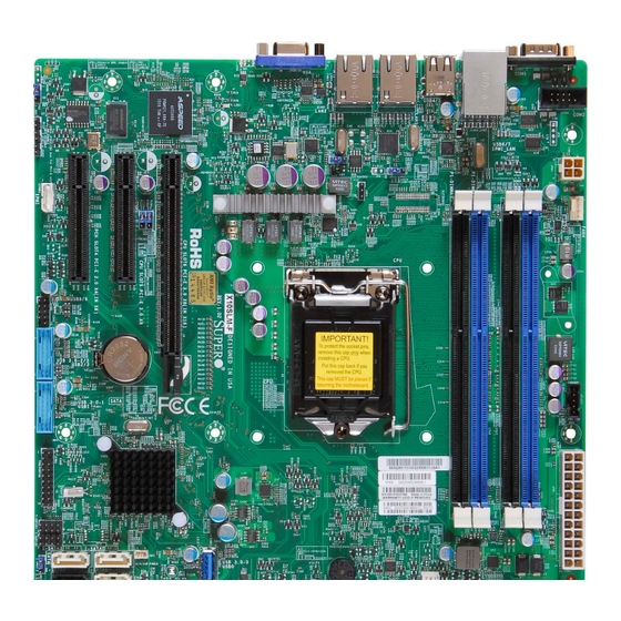
Chapter 1: Introduction Chapter 1 Introduction Overview Checklist Congratulations on purchasing your computer motherboard from an acknowledged leader in the industry. Supermicro boards are designed with the utmost attention to detail to provide you with the highest standards in quality and performance. Please check that the following items have all been included with your motherboard. - Page 10 X10SLM-F/X10SLL-F/X10SLL-SF/X10SLL-S User’s Manual X10SLM-F Motherboard Image Note: All graphics shown in this manual were based upon the latest PCB Revision available at the time of publishing of the manual. The motherboard you've received may or may not look exactly the same as the graphics shown in this manual.
- Page 11 Chapter 1: Introduction X10SLL-F Series Motherboard Image Note: All graphics shown in this manual were based upon the latest PCB Revision available at the time of publishing of the manual. The motherboard you've received may or may not look exactly the same as the graphics shown in this manual.
- Page 12 X10SLM-F/X10SLL-F/X10SLL-SF/X10SLL-S User’s Manual X10SLL-SF/-S Motherboard Layout Note: All graphics shown in this manual were based upon the latest PCB Revision available at the time of publishing of the manual. The motherboard you've received may or may not look exactly the same as the graphics shown in this manual.
- Page 13 Chapter 1: Introduction X10SLM-F_X10SLL-(F/SF/S) Motherboard Layout USB6/7 COM1 COM2 USB4/5 LED1 BMC FW LAN1 LAN2 CTRL IPMI_LAN BIOS JPL2 JPL1 X10SLM-F/X10SLL(-F/SF/S) Rev. 1.02 IPMI Code BAR Code MAC Code T-SGPIO1 T-SGPIO2 I-SATA3 JSD1 I-SATA0 JBT1 JSTBY1 JPME1 FP Control JBR1...
- Page 14 X10SLM-F/X10SLL-F/X10SLL-SF/X10SLL-S User’s Manual Differences among the models The table below summarizes the differences among the models: Model Variation Table Feature X10SLM-F X10SLL-F X10SLL-SF/-S Intel C224 Exp Intel C222 Exp Intel C222 Exp PCI-E Slot 1 PCI-E 3.0 x8 in x16, 1 PCI-E 3.0 x8 in x16,...
- Page 15 Chapter 1: Introduction X10SLM-F_X10SLL-(F/SF/S) Quick Reference USB6/7 COM1 COM2 USB4/5 LED1 BMC FW LAN1 LAN2 CTRL IPMI_LAN BIOS JPL2 JPL1 X10SLM-F/X10SLL(-F/SF/S) Rev. 1.02 IPMI Code BAR Code MAC Code T-SGPIO1 T-SGPIO2 I-SATA3 JSD1 I-SATA0 JBT1 JSTBY1 JPME1 FP Control JBR1...
- Page 16 (CPU) Slot 6 PCI-Express 3.0 x8 in x16 Slot (CPU) Slot 5 PCI-Express 3.0 x8 Slot (PCH) Slot 4 PCI-Express 2.0 x4 in x8 Slot (X10SLM-F/X10SLL-F Only) T-SGPIO 1/2 Serial Link General Purpose I/O Connection Headers 1/2 USB 3.0-0 (USB0)
- Page 17 Chapter 1: Introduction USB 3.0-2/3 (USB2/3) Front Accessible USB 3.0 Header 2/3 (for X10SLM-F Only) USB 4/5, 6/7 (2.0) Back panel USB 2.0 Ports 4/5, 6/7 (USB 6/7: for X10SLM-F & X10SLL-F Only) USB 8/9 Front Panel Accessible USB 2.0 Headers 8/9...
-
Page 18: Motherboard Features
Dual-channel memory DIMM sizes UDIMM 1 GB, 2 GB, 4GB, and 8GB Intel ® C224 Express (X10SLM-F), C222 (X10SLL Series) Chipset Expansion Slots One (1) PCI Express 3.0 x8 in x16 slot (CPU Slot 6), One (1) PCI Express 3.0 x8 (CPU Slot 5), One (1) PCI Express 2.0 x4 in x8 slot (PCH Slot 4 Not... - Page 19 Chapter 1: Introduction Serial (COM) Connections One (1) Front Accessible Serial Port header(COM2) (X10SLM-F/X10SLL-F) One (1) Serial Port on the rear I/O Panel (COM1) (X10SLM-F/X10SLL-F) Super I/O AST2400/AST1400 BMC (AXT2400 for -F models) BIOS 128 Mb AMI BIOS SPI Flash BIOS ®...
-
Page 20: System Block Diagram
X10SLM-F/X10SLL-F/X10SLL-SF/X10SLL-S User’s Manual X10SLM-F_X10SLL-(F/SF/S) Block Diagram #B-1 VR12.5 #B-0 3 PHASE #A-1 PCI-E X16 G3 #A-0 PCI-E x16 #0-15 BOM Select (Default: 2 *8) 4 CORE DDR-III #0-7 PCI-E x8(x16) #8-15 PCI-E x8 PCI-E X8 G3 3.0 Gb/S PCI-E X4 G2... -
Page 21: Chipset Overview
Chapter 1: Introduction Chipset Overview The X10SLM-F_X10SLL-(F/SF/S) supports Intel ® Xeon ® E3-1200 v3 and 4th Gen Core i3, Pentium and Celeron processors in an LGA 1150 (H3) Socket. Built upon the functionality and the capability of the C224/C222 Express chipset, the motherboard provides substantial enhancement to system performance and storage capability for high performance platforms in a sleek package. -
Page 22: Special Features
X10SLM-F/X10SLL-F/X10SLL-SF/X10SLL-S User’s Manual Special Features Recovery from AC Power Loss Basic I/O System (BIOS) provides a setting for you to determine how the system will respond when AC power is lost and then restored to the system. You can choose for the system to remain powered off, (in which case you must press the power switch to turn it back on), or for it to automatically return to a power-on state. -
Page 23: Acpi Features
Chapter 1: Introduction System Resource Alert This feature is available when the system is used with SuperDoctor® 5 in the Windows and Linux operating systems. SuperDoctor is used to notify the user of certain system events. For example, you can also configure SuperDoctor to provide you with warnings when the system temperature, CPU temperatures, voltages and fan speeds go beyond predefined thresholds. - Page 24 X10SLM-F/X10SLL-F/X10SLL-SF/X10SLL-S User’s Manual areas where noisy power transmission is present, you may choose to install a line filter to shield the computer from noise. It is recommended that you also install a power surge protector to help avoid problems caused by power surges.
-
Page 25: Chapter 2 Installation
Chapter 2: Installation Chapter 2 Installation Standardized Warning Statements The following statements are industry-standard warnings, provided to warn the user of situations which have the potential for bodily injury. Should you have questions or experience difficulty, contact Supermicro's Technical Support department for assis- tance. - Page 26 10SLM-F/X10SLL-F/X10SLL-SF/X10SLL-S User’s Manual Attention Danger d'explosion si la pile n'est pas remplacée correctement. Ne la remplacer que par une pile de type semblable ou équivalent, recommandée par le fabricant. Jeter les piles usagées conformément aux instructions du fabricant. ¡Advertencia! Existe peligro de explosión si la batería se reemplaza de manera incorrecta. Re- emplazar la batería exclusivamente con el mismo tipo o el equivalente recomen- dado por el fabricante.
-
Page 27: Product Disposal
Chapter 2: Installation Product Disposal Warning! Ultimate disposal of this product should be handled according to all national laws and regulations. 製品の廃棄 この製品を廃棄処分する場合、 国の関係する全ての法律 ・ 条例に従い処理する必要が あり ます。 警告 本产品的废弃处理应根据所有国家的法律和规章进行。 警告 本產品的廢棄處理應根據所有國家的法律和規章進行。 Warnung Die Entsorgung dieses Produkts sollte gemäß allen Bestimmungen und Gesetzen des Landes erfolgen. -
Page 28: Static-Sensitive Devices
10SLM-F/X10SLL-F/X10SLL-SF/X10SLL-S User’s Manual القىانين واللىائح الىطنية جميع وفقا ل ينبغي التعامل معه هذا المنتج من التخلص النهائي عند 경고! 이 제품은 해당 국가의 관련 법규 및 규정에 따라 폐기되어야 합니다. Waarschuwing De uiteindelijke verwijdering van dit product dient te geschieden in overeenstemming met alle nationale wetten en reglementen. -
Page 29: Processor And Heatsink Installation
Chapter 2: Installation Processor and Heatsink Installation Warning: When handling the processor package, avoid placing direct pressure on the label area of the fan. Important: • Always connect the power cord last, and always remove it before adding, re- moving or changing any hardware components. Make sure that you install the processor into the CPU socket before you install the CPU heatsink. - Page 30 10SLM-F/X10SLL-F/X10SLL-SF/X10SLL-S User’s Manual 2. Gently lift the load lever to open the load plate. Remove the plastic cap. 3. Use your thumb and your index finger to hold the CPU at the North center edge and the South center edge of the CPU. North Center Edge South Center Edge 4.
- Page 31 Chapter 2: Installation 5. Do not rub the CPU against the surface or against any pins of the socket to avoid damaging the CPU or the socket.) 6. With the CPU inside the socket, inspect the four corners of the CPU to make sure that the CPU is properly installed.
-
Page 32: Installing An Active Cpu Heatsink With Fan
10SLM-F/X10SLL-F/X10SLL-SF/X10SLL-S User’s Manual Installing an Active CPU Heatsink with Fan 1. Locate the CPU Fan power connec- tor on the motherboard. (Refer to the layout on the right for the CPU Fan location.) 2. Position the heatsink so that the heatsink fan wires are closest to the CPU fan power connector and are Thermal Grease... - Page 33 Chapter 2: Installation 7. Align the four heatsink fasten- ers with the mounting holes on the motherboard. Gently push the pairs of diagonal fasteners (#1 & #2, and #3 & #4) into the mounting holes until you hear a click. Also, make sure to orient each fastener so that the narrow end of the groove is pointing...
-
Page 34: Removing The Heatsink
10SLM-F/X10SLL-F/X10SLL-SF/X10SLL-S User’s Manual Removing the Heatsink Warning: We do not recommend that the CPU or the heatsink be removed. However, if you do need to remove the heatsink, please follow the instructions below to remove the heatsink and to prevent damage done to the CPU or other components. -
Page 35: Installing Ddr3 Memory
DIMMB2 (Channel B, Slot 2, blue slot. See the next page for the location). For the system to work properly, please use the memory X10SLM-F/X10SLL(-F/SF/S) modules of the same type and speed Rev. 1.02 IPMI Code BAR Code in the same motherboard. -
Page 36: Removing Memory Modules
10SLM-F/X10SLL-F/X10SLL-SF/X10SLL-S User’s Manual Removing Memory Modules Reverse the steps above to remove the DIMM modules from the motherboard. Memory Support Towards the CPU Slot A1 Slot A2 (Blue Slot) Slot B1 Slot B2 (Blue Slot) Towards the edge of the motherboard The X10SLM-F_X10SLL-(F/SF/S) supports up to 32GB of Unbuffered (UDIMM) DDR3 ECC 1600/1333 MHz in 4 memory slots. - Page 37 Chapter 2: Installation • For Microsoft Windows users: Microsoft implemented a design change with Windows Vista. This change is specific to the behavior of Physical Address Extension (PAE) mode which improves driver compatibility. For more in- formation, please read the following article at Microsoft’s Knowledge Base website at: http://support.microsoft.com/kb/888137.
-
Page 38: Motherboard Installation
Only if Needed Location of Mounting Holes USB6/7 COM1 COM2 USB4/5 LED1 BMC FW LAN1 LAN2 CTRL IPMI_LAN BIOS JPL2 JPL1 X10SLM-F/X10SLL(-F/SF/S) Rev. 1.02 IPMI Code BAR Code MAC Code T-SGPIO1 T-SGPIO2 I-SATA3 JSD1 I-SATA0 JBT1 JSTBY1 JPME1 FP Control JBR1... -
Page 39: Installing The Motherboard
Chapter 2: Installation Installing the Motherboard 1. Install the I/O shield into the back of the chassis. 2. Locate the mounting holes on the motherboard. (See the previous page.) 3. Locate the matching mounting holes on the chassis. Align the mounting holes on the motherboard against the mounting holes on the chassis. -
Page 40: Connectors/Io Ports
I-SATA4 I-SATA1 I-SATA5 I-SATA2 Backplane I/O Panel A. COM1 F. USB Port 5 (2.0) (Available on X10SLM-F/X10SLL-F) B. USB Port 6 (2.0) G. LAN1 C. USB Port 7 (2.0) H. LAN2 D. IPMI LAN I. VGA E. USB Port 4 (2.0) -
Page 41: Serial Ports
COM2 Video Connection A Video (VGA) port is located next to LAN2 on the I/O backplane. Refer to the board layout below for the location. A. COM1 (Available on X10SLM-F/X10SLL-F) B. COM2 (Available on X10SLM-F/X10SLL-F) C. VGA USB6/7 COM1 COM2... -
Page 42: Universal Serial Bus (Usb)
X10SLL-S/SF. In addition, three USB 3.0 headers (four USB 3.0 connections: 0, 1, 2/3) are located on the X10SLM-F, two USB 3.0 headers (USB 0, 1) are located on the X10SLL-F. A USB 2.0 header with two USB 2.0 connections (USB 8/9) are also located on X10SLM/X10SLL to provide front chassis access using USB cables (not included). -
Page 43: Ethernet Ports
B. LAN2 C. IPMI_LAN (-F models only) USB6/7 COM1 COM2 USB4/5 LED1 BMC FW LAN1 LAN2 CTRL IPMI_LAN BIOS JPL2 JPL1 X10SLM-F/X10SLL(-F/SF/S) Rev. 1.02 IPMI Code BAR Code MAC Code T-SGPIO1 T-SGPIO2 I-SATA3 JSD1 I-SATA0 JBT1 JSTBY1 JPME1 FP Control JBR1... -
Page 44: Front Control Panel
LED indicators. Refer to the following section for descriptions and pin definitions. USB6/7 COM1 COM2 USB4/5 LED1 BMC FW LAN1 LAN2 CTRL IPMI_LAN BIOS JPL2 JPL1 X10SLM-F/X10SLL(-F/SF/S) Rev. 1.02 IPMI Code BAR Code MAC Code T-SGPIO1 T-SGPIO2 I-SATA3 JSD1 I-SATA0 JBT1 JSTBY1 JPME1 FP Control JBR1... -
Page 45: Front Control Panel Pin Definitions
FP PWRLED 3.3 V UID Switch HDD LED NIC1 Activity LED 3.3V Stby 3.3V Stby NIC2 Activity LED OH/Fan Fail Blue LED X10SLM-F/X10SLL(-F/SF/S) Rev. 1.02 IPMI Code Power Fail LED 3.3V BAR Code MAC Code Reset Reset Button T-SGPIO1 Ground... -
Page 46: Hdd Led
3.3 V FP PWRLED HDD LED UID Switch NIC1 Activity LED 3.3V Stby 3.3V Stby NIC2 Activity LED OH/Fan Fail Blue LED X10SLM-F/X10SLL(-F/SF/S) Rev. 1.02 Power Fail LED 3.3V IPMI Code BAR Code MAC Code Reset Reset Button Ground T-SGPIO1... -
Page 47: Overheat (Oh)/Fan Fail Led
JPL2 JPL1 Ground FP PWRLED 3.3 V UID Switch HDD LED NIC1 Activity LED 3.3V Stby 3.3V Stby NIC2 Activity LED X10SLM-F/X10SLL(-F/SF/S) OH/Fan Fail Blue LED Rev. 1.02 IPMI Code BAR Code Power Fail LED 3.3V MAC Code T-SGPIO1 T-SGPIO2... -
Page 48: Reset Button
3.3 V FP PWRLED HDD LED UID Switch NIC1 Activity LED 3.3V Stby 3.3V Stby NIC2 Activity LED OH/Fan Fail Blue LED X10SLM-F/X10SLL(-F/SF/S) Rev. 1.02 IPMI Code Power Fail LED 3.3V BAR Code MAC Code Reset Reset Button Ground T-SGPIO1... -
Page 49: Connecting Cables
A. 24-Pin ATX Main PWR USB4/5 LED1 BMC FW LAN1 LAN2 CTRL IPMI_LAN BIOS (Required) JPL2 JPL1 B. 4-Pin PWR (Recom- mended) X10SLM-F/X10SLL(-F/SF/S) Rev. 1.02 IPMI Code BAR Code MAC Code T-SGPIO1 T-SGPIO2 I-SATA3 I-SATA0 JSD1 JBT1 JSTBY1 JPME1 FP Control... -
Page 50: Fan Headers (Fan 1- Fan 4/Fan A)
LED1 BMC FW C. Fan 3 LAN1 LAN2 CTRL IPMI_LAN BIOS D. Fan 4 JPL2 JPL1 E. Fan A F. Chassis Intrusion X10SLM-F/X10SLL(-F/SF/S) Rev. 1.02 IPMI Code BAR Code MAC Code T-SGPIO1 T-SGPIO2 I-SATA3 JSD1 I-SATA0 JBT1 JSTBY1 JPME1 FP Control... -
Page 51: Internal Buzzer
A. Internal Buzzer USB6/7 COM1 B. Speaker Header COM2 USB4/5 LED1 BMC FW LAN1 LAN2 CTRL IPMI_LAN BIOS JPL2 JPL1 X10SLM-F/X10SLL(-F/SF/S) Rev. 1.02 IPMI Code BAR Code MAC Code T-SGPIO1 T-SGPIO2 I-SATA3 JSD1 I-SATA0 JBT1 JSTBY1 JPME1 FP Control JBR1... -
Page 52: Dom Pwr Connector (Jsd1)
A. DOM PWR USB6/7 COM1 COM2 B. Wake-On-LAN USB4/5 LED1 BMC FW LAN1 LAN2 CTRL IPMI_LAN BIOS JPL2 JPL1 X10SLM-F/X10SLL(-F/SF/S) Rev. 1.02 IPMI Code BAR Code MAC Code T-SGPIO1 T-SGPIO2 I-SATA3 I-SATA0 JSD1 JBT1 JSTBY1 JPME1 FP Control JBR1 FANA FAN3... -
Page 53: T-Sgpio 1/2 Headers
A.T-SGPIO 1 USB6/7 COM1 COM2 B.T-SGPIO 2 USB4/5 LED1 BMC FW LAN1 LAN2 CTRL IPMI_LAN C.JTPM1 BIOS JPL2 JPL1 X10SLM-F/X10SLL(-F/SF/S) Rev. 1.02 IPMI Code BAR Code MAC Code T-SGPIO1 T-SGPIO2 I-SATA3 I-SATA0 JSD1 JBT1 JSTBY1 JPME1 FP Control JBR1 FANA FAN3... -
Page 54: Power Smb (I 2 C) Connector
A. PWR SMB USB6/7 COM1 COM2 B. IPMB USB4/5 LED1 BMC FW LAN1 LAN2 CTRL IPMI_LAN BIOS JPL2 JPL1 X10SLM-F/X10SLL(-F/SF/S) Rev. 1.02 IPMI Code BAR Code MAC Code T-SGPIO1 T-SGPIO2 I-SATA3 I-SATA0 JSD1 JBT1 JSTBY1 JPME1 FP Control JBR1 FANA FAN3... -
Page 55: Jumper Settings
A. JPL1: LAN1 Enable COM1 COM2 B. JPL2: LAN2 Enable USB4/5 LED1 BMC FW LAN1 LAN2 CTRL IPMI_LAN BIOS JPL2 JPL1 X10SLM-F/X10SLL(-F/SF/S) Rev. 1.02 IPMI Code BAR Code MAC Code T-SGPIO1 T-SGPIO2 I-SATA3 I-SATA0 JSD1 JBT1 JSTBY1 JPME1 FP Control... -
Page 56: Watch Dog Enable/Disable
USB6/7 COM1 B. JI COM2 USB4/5 LED1 BMC FW C. JI LAN1 LAN2 CTRL IPMI_LAN BIOS JPL2 JPL1 X10SLM-F/X10SLL(-F/SF/S) Rev. 1.02 IPMI Code BAR Code MAC Code T-SGPIO1 T-SGPIO2 I-SATA3 JSD1 I-SATA0 JBT1 JSTBY1 JPME1 FP Control JBR1 FANA FAN3... -
Page 57: Vga Enable
A. VGA Enable B. BIOS Recovery Enable USB6/7 COM1 COM2 USB4/5 LED1 BMC FW LAN1 LAN2 CTRL IPMI_LAN BIOS JPL2 JPL1 X10SLM-F/X10SLL(-F/SF/S) Rev. 1.02 IPMI Code BAR Code MAC Code T-SGPIO1 T-SGPIO2 I-SATA3 JSD1 I-SATA0 JBT1 JSTBY1 JPME1 FP Control JBR1... -
Page 58: Management Engine (Me) Recovery
B. Manufacturer Mode Select the right for jumper settings. USB6/7 COM1 COM2 USB4/5 LED1 BMC FW LAN1 LAN2 CTRL IPMI_LAN BIOS JPL2 JPL1 X10SLM-F/X10SLL(-F/SF/S) Rev. 1.02 IPMI Code BAR Code MAC Code T-SGPIO1 T-SGPIO2 I-SATA3 JSD1 I-SATA0 JBT1 JSTBY1 JPME1 FP Control JBR1... -
Page 59: Onboard Indicators
USB6/7 COM1 COM2 B. IPMI_LAN LED (for -F USB4/5 LED1 BMC FW LAN1 LAN2 models) CTRL IPMI_LAN BIOS JPL2 JPL1 X10SLM-F/X10SLL(-F/SF/S) Rev. 1.02 IPMI Code BAR Code MAC Code T-SGPIO1 T-SGPIO2 I-SATA3 JSD1 I-SATA0 JBT1 JSTBY1 JPME1 FP Control JBR1... -
Page 60: Onboard Power Led
A. Onboard PWR LED USB6/7 COM1 B. BMC LED (-F models) COM2 USB4/5 LED1 BMC FW LAN1 LAN2 CTRL IPMI_LAN BIOS JPL2 JPL1 X10SLM-F/X10SLL(-F/SF/S) Rev. 1.02 IPMI Code BAR Code MAC Code T-SGPIO1 T-SGPIO2 I-SATA3 JSD1 I-SATA0 JBT1 JSTBY1 JPME1 FP Control JBR1... -
Page 61: 2-10 Serial Ata (Sata) Connections
Four Serial ATA (SATA) 3.0 connectors (I-SATA 0-3) and two SATA 2.0 (I-SATA 4/5) are located on the X10SLM-F motherboard. These SATA ports are supported by the Intel C224 PCH chip. These SATA ports support RAID 0, 1, 10, and 5. Serial Link connections provide faster data transmission than legacy Parallel ATA. -
Page 62: Sata Connections (For The X10Sll-F/X10Sll-Sf/X10Sll-S)
LAN1 LAN2 CTRL IPMI_LAN BIOS D. I-SATA 2.0 #3 JPL2 E. I-SATA 2.0 #4 JPL1 (X10SLL-F Only) F. I-SATA 2.0 #5 (X10SLL-F Only) X10SLM-F/X10SLL(-F/SF/S) Rev. 1.02 IPMI Code BAR Code MAC Code T-SGPIO1 T-SGPIO2 I-SATA3 JSD1 I-SATA0 JBT1 JSTBY1 JPME1... -
Page 63: Chapter 3 Troubleshooting
Chapter 3: Troubleshooting Chapter 3 Troubleshooting Troubleshooting Procedures Use the following procedures to troubleshoot your system. If you have followed all of the procedures below and still need assistance, refer to the ‘Technical Support Procedures’ and/or ‘Returning Merchandise for Service’ section(s) in this chapter. Always disconnect the AC power cord before adding, changing or installing any hardware components. -
Page 64: Memory Errors
X10SLM-F/X10SLL-F/X10SLL-SF/X10SLL-S User’s Manual No Video 1. If the power is on, but you have no video--in this case, you will need to re- move all the add-on cards and cables first. 2. Use the speaker to determine if any beep codes exist. (Refer to Appendix A for details on beep codes.) -
Page 65: Technical Support Procedures
Chapter 3: Troubleshooting Technical Support Procedures Before contacting Technical Support, please make sure that you have followed all the steps listed below. Also, Note that as a motherboard manufacturer, Supermicro does not sell directly to end users, so it is best to first check with your distributor or reseller for troubleshooting services. -
Page 66: Frequently Asked Questions
X10SLM-F/X10SLL-F/X10SLL-SF/X10SLL-S User’s Manual Frequently Asked Questions Question: What type of memory does my motherboard support? Answer: The X10SLM-F_X10SLL-(F/SF/S) supports up to 32GB of unbuffered ECC DDR3 DIMM (1.35V/1.5V, 1600/1333 MHz). See Section 2-4 for details on installing memory. Question: How do I update my BIOS? Answer: We do NOT recommend that you upgrade your BIOS if you are not experiencing any problems with your system. -
Page 67: Battery Removal And Installation
Chapter 3: Troubleshooting Important: The SPI BIOS chip installed on this motherboard is not re- movable. To repair or replace a damaged BIOS chip, please send your motherboard to RMA at Supermicro for service. Question: I think my BIOS is corrupted. How can I recover my BIOS? Answer: Please see Appendix C-BIOS Recovery for detailed instructions. -
Page 68: Returning Merchandise For Service
X10SLM-F/X10SLL-F/X10SLL-SF/X10SLL-S User’s Manual Proper Battery Disposal Warning: Please handle used batteries carefully. Do not damage the battery in any way; a damaged battery may release hazardous materials into the environment. Do not discard a used battery in the garbage or a public landfill. Please comply with the regulations set up by your local hazardous waste management agency to dispose of your used battery properly. -
Page 69: Chapter 4 Bios
BIOS Introduction This chapter describes the AMI BIOS Setup Utility for the X10SLM-F/X10SLL-F/ X10SLL-SF/X10SLL-S . The ROM BIOS is stored in a Flash EEPROM and can be easily updated. This chapter describes the basic navigation of the AMI BIOS Setup Utility setup screens. -
Page 70: Main Setup
X10SLM-F/X10SLL-F/X10SLL-SF/X10SLL-S User’s Manual How to Start the Setup Utility Normally, the only visible Power-On Self-Test (POST) routine is the memory test. As the memory is being tested, press the <Delete> key to enter the main menu of the AMI BIOS Setup Utility. From the main menu, you can access the other setup screens. - Page 71 Day MM/DD/YY format. The time is entered in HH:MM:SS format. Note: The time is in the 24-hour format. For example, 5:30 P.M. appears as 17:30:00. The following BIOS items will also be displayed: Supermicro X10SLM-F Version Build Date Memory Information...
-
Page 72: Advanced Setup Configurations
X10SLM-F/X10SLL-F/X10SLL-SF/X10SLL-S User’s Manual Advanced Setup Configurations Use the arrow keys to select Boot Setup and press <Enter> to access the submenu items: Warning: Take Caution when changing the Advanced settings. An incorrect value, a very high DRAM frequency or an incorrect DRAM timing setting may cause system to become unstable. -
Page 73: Power Configuration
Chapter 4: AMI BIOS Bootup Num-Lock This feature selects the Power-on state for the Numlock key. The options are Off and On. Wait For 'F1' If Error This feature forces the system to wait until the 'F1' key is pressed if an error oc- curs. - Page 74 X10SLM-F/X10SLL-F/X10SLL-SF/X10SLL-S User’s Manual CPU Configuration The following CPU information will be displayed: • Type of CPU • CPU Signature • Microcode Patch • Maximum CPU Speed • Minimum CPU Speed • CPU Speed • Processor Cores • Intel HT(Hyper-Threading) Technology •...
- Page 75 Chapter 4: AMI BIOS Hyper-threading Select Enabled to support Intel Hyper-threading Technology to enhance CPU per- formance. The options are Enabled and Disabled. Active Processor Cores This feature determines how many CPU cores will be activated for each CPU. When all is selected, all cores in the CPU will be activated.
- Page 76 X10SLM-F/X10SLL-F/X10SLL-SF/X10SLL-S User’s Manual CPU AES Select Enable to enable Intel CPU Advanced Encryption Standard (AES) Instruc- tions for CPU to enhance data integrity. The options are Enabled and Disabled. EIST EIST (Enhanced Intel SpeedStep Technology) allows the system to automatically adjust processor voltage and core frequency in an effort to reduce power consump- tion and heat dissipation.
- Page 77 Chapter 4: AMI BIOS 1-Core Ratio Limit (Available when "Turbo Mode" is set to Enabled) This increases (multiplies) 1 clock speed in the CPU core in relation to the bus speed when one CPU core is active. Press "+" or "-" on your keyboard to change this value.
- Page 78 X10SLM-F/X10SLL-F/X10SLL-SF/X10SLL-S User’s Manual CPU C3 Report (Available when "CPU C-States" is set to Enabled) Select Enabled to allow the BIOS to report the CPU C3 State (ACPI C2) to the operating system. During the CPU C3 State, the CPU clock generator is turned off.
-
Page 79: Chipset Configuration
Chapter 4: AMI BIOS LakeTiny Feature Select Enabled for LakeTing feature support. The options are Disabled and En- abled. ACPI T State Select Enabled for ACPI T state (processor throttling) feature support. The options are Disabled and Enabled. Chipset Configuration WARNING: Setting the wrong values in the following sections may cause the system to malfunction. -
Page 80: Memory Configuration
X10SLM-F/X10SLL-F/X10SLL-SF/X10SLL-S User’s Manual PEG1 - Gen X This item allows the generation configuration of PEG1 on the PCI-E slot. The options are Auto, Gen1, Gen2 and Gen3. Detect Non-Compliance Device Select Enabled for the AMI BIOS will automatically detect a PCI-E device that is not in compliance. - Page 81 Chapter 4: AMI BIOS • Minimum Delay Time • CAS to RAS (tRCDmin) • Row Precharge (tRPmin) • Active to Precharege (tRASmin) Memory Frequency Limiter This feature sets the limit of memory frequency for DIMM modules installed on the the motherboard. The options are 1067 (MHz), 1333 (MHz), 1600 (MHz), and Auto.
- Page 82 X10SLM-F/X10SLL-F/X10SLL-SF/X10SLL-S User’s Manual Select Enabled to enable EHCI (Enhanced Host Controller Interface) Controller 2 for USB 2.0 support. One EHCI controller must always be enabled. The settings are Enabled and Disabled.. Legacy USB Support This feature enables support for legacy USB devices. Select Auto to disable legacy support if USB devices are not present.
-
Page 83: Sata Configuration
Chapter 4: AMI BIOS SATA Configuration of the SATA Devices and displays the following items: SATA Controllers This item Enables or Disables the built-in SATA controllers on the motherboard. The options are Enabled and Disabled. SATA Mode Selection This item selects the mode for the installed SATA drives. The options are IDE, AHCI and RAID. - Page 84 X10SLM-F/X10SLL-F/X10SLL-SF/X10SLL-S User’s Manual Serial ATA Port 0~ Port 5 This item displays the information detected on the installed SATA drives on the particular SATA port. • Model number of drive and capacity • Software Preserve Support If the item above - SATA Mode Select is set to RAID, the following items are...
- Page 85 Chapter 4: AMI BIOS VGA Palette Snoop Select Enabled to support VGA palette register snooping which will allow the PCI cards that do not contain their own VGA color palette to examine the video cards palette and mimic it for proper color display. The options are Disabled and Enabled.
-
Page 86: Acpi Settings
X10SLM-F/X10SLL-F/X10SLL-SF/X10SLL-S User’s Manual ment) to boot the computer using a PXE device installed in a LAN port specified. Select Disabled to prevent system boot using a device installed in a LAN port. The options are Disabled, PXE and iSCSI. The default setting for Onboard LAN1 Op- tion ROM is PXE. -
Page 87: Super Io Configuration
• ME FW SKU Information • End-of-POST Status Super IO Configuration Super IO Chip NCT6776F Serial Port 1 Configuration Serial Port Select Enabled to enable the onboard serial port. The options are Enabled and Disabled. Change Port 1 Settings This feature specifies the base I/O port address and the Interrupt Request ad- dress of Serial Port 1. -
Page 88: Console Redirection Settings
X10SLM-F/X10SLL-F/X10SLL-SF/X10SLL-S User’s Manual SOL Change Settings This feature specifies the base I/O port address and the Interrupt Request ad- dress of SOL Serial Port. Select Auto to let the BIOS automatically assign the base I/O and IRQ address. The options for Serial Port 2 are Auto, (IO=2F8h;... - Page 89 Chapter 4: AMI BIOS Stop Bits A stop bit indicates the end of a serial data packet. Select 1 Stop Bit for standard serial data communication. Select 2 Stop Bits if slower devices are used. The options are 1 and 2. Flow Control This feature allows the user to set the flow control for Console Redirection to prevent data loss caused by buffer overflow.
- Page 90 X10SLM-F/X10SLL-F/X10SLL-SF/X10SLL-S User’s Manual Console Redirection (for EMS) Select Enabled to use a COM Port selected by the user for Console Redirection. The options are Enabled and Disabled. Console Redirection Settings (for EMS) This feature allows the user to specify how the host computer will exchange data with the client computer, which is the remote computer used by the user.
-
Page 91: Event Logs
Chapter 4: AMI BIOS Event Logs Change SMBIOS Event Log Settings Enabling/Disabling Options SMBIOS Event Log Change this item to enable or disable all features of the SMBIOS Event Logging during system boot. The options are Enabled and Disabled. Erasing Settings Erase Event Log If No is selected, data stored in the event log will not be erased. -
Page 92: View Smbios Event Log
X10SLM-F/X10SLL-F/X10SLL-SF/X10SLL-S User’s Manual SMBIOS Event Long Standard Settings Log System Boot Event This option toggles the System Boot Event logging to enabled or disabled. The options are Disabled and Enabled. MECI The Multiple Event Count Increment (MECI) counter counts the number of oc- curences a duplicate event must happen before the MECI counter is incremented. - Page 93 Chapter 4: AMI BIOS The following IPMI information will be displayed: • IPMI Firmware Revision • IPMI Status System Event Log This feature is used to change the Sytem Event Log (SEL) configuration. SEL Components - Change this item to enable or disable all features of System Event Logging.
-
Page 94: Bmc Network Configuration
X10SLM-F/X10SLL-F/X10SLL-SF/X10SLL-S User’s Manual BMC Network Configuration LAN Channel 1: This feature allows the user to configure the settings for LAN1 Port. Update IPMI LAN Configuration This feature allows the BIOS to implement any IP/MAC address changes at the next system boot. -
Page 95: Boot Settings
Chapter 4: AMI BIOS Boot Settings Use this feature to configure Boot Settings: Set Boot Priority This option prioritizes the order of bootable devices that the system to boot from. Press [ENTER] on each entry from top to bottom to select devices. •... - Page 96 X10SLM-F/X10SLL-F/X10SLL-SF/X10SLL-S User’s Manual Delete Boot Option This feature allows the user to delete a previously defined boot device from which the systems boots during startup. The settings are [any pre defined boot device] Delete Driver Option This feature allows the user to delete a previously defined boot device from which the systems boots during startup.
-
Page 97: Security Settings
Chapter 4: AMI BIOS Security Settings This menu allows the user to configure the following security settings for the system. • If the Administrator password is defined ONLY - this controls access to the BIOS setup ONLY. • If the User's password is defined ONLY - this password will need to be entered upon each system boot, and will also have Administrator rights in the setup. -
Page 98: Save & Exit
X10SLM-F/X10SLL-F/X10SLL-SF/X10SLL-S User’s Manual Save & Exit Select the Exit tab from the BIOS Setup Utility screen to enter the Exit BIOS Setup screen. Discard Changes and Exit Select this option to quit the BIOS Setup without making any permanent changes to the system configuration, and reboot the computer. - Page 99 Chapter 4: AMI BIOS Restore Optimized Defaults To set this feature, select Restore Defaults from the Exit menu and press <Enter>. These are factory settings designed for maximum system stability, but not for maximum performance. Save As User Defaults To set this feature, select Save as User Defaults from the Exit menu and press <En- ter>.
- Page 100 X10SLM-F/X10SLL-F/X10SLL-SF/X10SLL-S User’s Manual Notes 4-32...
-
Page 101: Appendix A Bios Error Beep Codes
Appendix A: POST Error Beep Codes Appendix A BIOS Error Beep Codes During the POST (Power-On Self-Test) routines, which are performed each time the system is powered on, errors may occur. Non-fatal errors are those which, in most cases, allow the system to continue with bootup. - Page 102 X10SLM-F/X10SLL-F/X10SLL-SF/X10SLL-S User’s Manual Notes...
-
Page 103: Appendix B Software Installation Instructions
Appendix B: Software Installation Instructions Appendix B Software Installation Instructions B-1 Installing Software Programs The Supermicro ftp site contains drivers and utilities for your system at ftp://ftp. supermicro.com. Some of these must be installed, such as the chipset driver. After accessing the ftp site, go into the CDR_Images directory and locate the ISO file for your motherboard. -
Page 104: B-2 Installing Superdoctor5
X10SLM-F/X10SLL-F/X10SLL-SF/X10SLL-S User’s Manual B-2 Installing SuperDoctor5 The Supermicro SuperDoctor® 5 is a hardware monitoring program that functions in a command-line or web-based interface in Windows and Linux operating systems. The program monitors system health information such as CPU temperature, system voltages, system power consumption, fan speed, and provides alerts via email or Simple Network Management Protocol (SNMP). -
Page 105: Appendix C Uefi Bios Recovery Instructions
Appendix C: UEFI BIOS Recovery Appendix C UEFI BIOS Recovery Instructions Warning: Do not upgrade the BIOS unless your system has a BIOS-related issue. Flashing the wrong BIOS can cause irreparable damage to the system. In no event shall Supermicro be liable for direct, indirect, special, incidental, or consequential damages arising from a BIOS update. - Page 106 To perform UEFI BIOS recovery using a USB-attached device, follow the instruc- tions below. 1. Using a different machine, copy the "Super.ROM" binary image file into the disc Root "\" Directory of a USB device or a writeable CD/DVD. Note: If you cannot locate the "Super.ROM" file in your driver disk, visit our website at www.supermicro.com to download the BIOS image into...
- Page 107 Appendix C: UEFI BIOS Recovery 6. After the process of BIOS Recovery is complete, press any key to reboot the system. 7. Using a different system, extract the BIOS package into a bootable USB flash drive. 8. When a DOS prompt appears, enter AMI.BAT BIOSname.### at the prompt. Note: Do not interrupt this process until BIOS flashing is completed.
- Page 108 X10SLM-F/X10SLL-F/X10SLL-SF/X10SLL-S User’s Manual 9. After seeing the message that BIOS update is completed, unplug the AC pow- er cable from the power supply to clear CMOS, and then plug the AC power cable in the power supply again to power on the system.
-
Page 109: Appendix D Dual Boot Block
Appendix D: Dual Boot Block Appendix D Dual Boot Block D-1 Introduction This motherboard supports the Dual Boot Block feature, which is the last-ditch mechanism to recover the BIOS boot block. This section provides an introduction to the feature. BIOS Boot Block A BIOS boot block is the minimum BIOS loader required to enable necessary hardware components for the BIOS crisis recovery flash that will update the main BIOS block. -
Page 110: D-2 Steps To Reboot The System By Using Jumper Jbr1
X10SLM-F/X10SLL-F/X10SLL-SF/X10SLL-S User’s Manual D-2 Steps to Reboot the System by Using Jumper JBR1 1. Power down the system. 2. Close pins 2-3 on Jumper JBR1, and power on the system. 3. Follow the BIOS recovery SOP listed in the previous chapter (Appendix C). - Page 111 (Disclaimer Continued) The products sold by Supermicro are not intended for and will not be used in life support systems, medical equipment, nuclear facilities or systems, aircraft, aircraft devices, aircraft/emergency com- munication devices or other critical systems whose failure to perform be reasonably expected to result in significant injury or loss of life or catastrophic property damage.
Need help?
Do you have a question about the X10SLM-F and is the answer not in the manual?
Questions and answers