Table of Contents
Advertisement
Quick Links
MEDIA RECEIVER
THIS MANUAL IS APPLICABLE TO THE FOLLOWING MODEL(S) AND TYPE(S).
Model
Type
PDP-R06XE
WYVIXK5
PDP-R06FE
WYVI5
PDP-R06FE
WYVIXK5
This service manual should be used together with the following manual(s).
Model No.
PDP-R06XE, PDP-R06FE
For details, refer to "Important Check Points for good servicing".
PIONEER CORPORATION
PIONEER ELECTRONICS (USA) INC. P.O. Box 1760, Long Beach, CA 90801-1760, U.S.A.
PIONEER EUROPE NV Haven 1087, Keetberglaan 1, 9120 Melsele, Belgium
PIONEER ELECTRONICS ASIACENTRE PTE. LTD. 253 Alexandra Road, #04-01, Singapore 159936
PIONEER CORPORATION 2005
Power Requirement
AC220-240V
AC220-240V
AC220-240V
Order No.
ARP3276
SCHEMATIC DIAGRAM, PCB CONNECTION DIAGRAM
4-1, Meguro 1-chome, Meguro-ku, Tokyo 153-8654, Japan
PDP-R06XE
Remarks
ORDER NO.
ARP3275
Remarks
T-IZR AUG. 2005 printed in Japan
Advertisement
Table of Contents
Troubleshooting

Related Manuals for Pioneer PDP-R06XE


Summary of Contents for Pioneer PDP-R06XE
- Page 1 PIONEER CORPORATION 4-1, Meguro 1-chome, Meguro-ku, Tokyo 153-8654, Japan PIONEER ELECTRONICS (USA) INC. P.O. Box 1760, Long Beach, CA 90801-1760, U.S.A. PIONEER EUROPE NV Haven 1087, Keetberglaan 1, 9120 Melsele, Belgium PIONEER ELECTRONICS ASIACENTRE PTE. LTD. 253 Alexandra Road, #04-01, Singapore 159936 PIONEER CORPORATION 2005 T-IZR AUG.
-
Page 2: Safety Information
PIONEER Service Manual. A subscription to, or additional copies Also test with plug reversed of, PIONEER Ser vice Manual may be obtained at a (Using AC adapter Earth nominal charge from PIONEER. plug as required) - Page 3 To protect products from damages or failures during transit, the shipping mode should be set or the shipping screws should be installed before shipment. Please be sure to follow this method especially if it is specified in this manual. PDP-R06XE...
-
Page 4: Table Of Contents
3.2 R06 D-TUNER ASSY..........................18 3.3 POWER SUPPLY UNIT..........................19 3.4 POWER SUPPLY SIGNAL ROUTE ......................20 3.5 PC CARD Module (PDP-R06XE Only) ....................21 3.6 VOLTAGES ............................... 22 3.7 WAVEFORMS ............................24 4. PCB CONNECTION DIAGRAM (Refer to “Service Manual : ARP3276”) 5. -
Page 5: Specifications
1. SPECIFICATIONS PDP-R06XE model Item Media Receiver, Model: PDP-R06XE Colour System Analogue PAL/SECAM/NTSC 3.58/NTSC 4.43/PAL 60 Digital PAL/SECAM Receiving System B/G, D/K, I, L/L' TV Function (Analogue) Tuner VHF/UHF E2–E69ch, F2–F10ch, I21–I69ch, IR A–IR Jch CATV Hyper-band, S1–S41ch Auto Channel Preset... - Page 6 FontAvenue is a registered trademark of NEC Corporation. • HDMI, the HDMI logo and High-Definition Multimedia Interface are trademarks or registered trademarks of HDMI Licensing LLC. • The names of companies or institutions are trademarks or registered trademarks of the respective companies or institutions. PDP-R06XE...
- Page 7 Power cord (2 m) (For UK and Eire) (For Europe, except UK and Eire) (ADG1214) Remote control unit (PDP-R06XE : AXD1509) Only the power cord that is appropriate in your country or region (PDP-R06FE : AXD1491) is supplied. System cable (3 m)
-
Page 8: Exploded Views And Parts List
Screws adjacent to mark on product are used for disassembly. For the applying amount of lubricants or glue, follow the instructions in this manual. (In the case of no amount instructions, apply as you think it appropriate.) 2.1 PACKING SECTION PDP-R06XE... - Page 9 AHG1337 NSP 15 Catalogue Bag AHG1340 Laminate Sheet AHG1350 Air Cap Bag AHG1351 (2) CONTRAST TABLE PDP-R06XE/WYVIXK5, PDP-R06FE/WYVI5 and WYVIXK5 are constructed the same except for the following: PDP-R06XE PDP-R06FE PDP-R06FE Mark No. Symbol and Description /WYVIXK5 /WYVI5 /WYVIXK5 1 Operating Instructions (Italian, Dutch, Spanish)
- Page 10 2.2 EXTERIOR SECTION PDP-R06XE only PDP-R06XE only PDP-R06XE only Cleaning paper GED-008 PDP- R06XE only Cleaning paper GED-008 PDP-R06XE only PDP-R06XE Refer to only "2.3 FRONT PANEL SECTION". PDP-R06FE only PDP-R06FE only PDP-R06XE...
- Page 11 Floating Rubber 60 AEB1410 Floating Rubber 40 See Contrast table (2) TERAOKA No.570F 16mm(W) GYH1001 Flat Clamp AEC1858 (2) CONTRAST TABLE PDP-R06XE/WYVIXK5, PDP-R06FE/WYVI5 and WYVIXK5 are constructed the same except for the following: PDP-R06XE PDP-R06FE PDP-R06FE Mark Symbol and Description /WYVIXK5 /WYVI5...
- Page 12 PDP-R06XE PDP-R06FE PDP-R06FE Mark Symbol and Description /WYVIXK5 /WYVI5 /WYVIXK5 > 23 Shield Plate ANG2838 Not used Not used 25 Floating Rubber 40 AEB1413 Not used Not used 30 Rear Cover AMR3425 Not used Not used 32 Fan Holder 40...
- Page 13 • Pasting up location WEEE Label (No.38) XE Remote Control Unit FE Remote Control Unit (AXD1509) (AXD1491) PDP-R06XE...
-
Page 14: Front Panel Section
2.3 FRONT PANEL SECTION PDP-R06XE... - Page 15 See Contrast table (2) NSP 20 LED Lens AMR3452 Rubber Foot VEB1349 Screw BPZ30P080FTB (2) CONTRAST TABLE PDP-R06XE/WYVIXK5, PDP-R06FE/WYVI5 and WYVIXK5 are constructed the same except for the following: PDP-R06XE PDP-R06FE PDP-R06FE Mark No. Symbol and Description /WYVIXK5 /WYVI5 /WYVIXK5...
-
Page 16: Overall Block Diagram
EXDIO_VDEC EXA_VDEC R2S11002AFT AV SW MON_OUT_L/R IC6002 K4S161622H-TC60 MUTE3 16M SDRAM MON_OUT_V (Main VDEC) Input 3 PDP-R06XE only SUB_Y/C IC6001 SDA_MA TVP5150AM1PBS SCL_MA SUB VDEC Input 5 for XE HDMI_RCH/LCH Input 4 for FE A_MUTE Input 5/PC for XE HP_L/R... - Page 17 IC5206 BUFFER MB91305PMC-G-BND IC6404 MAIN UCOM SII9021CTU HDMI Rx REM_B MTXD MRXD TXD_DT A0-19 RXD_DT DQ0-15 AUDIO_L/R IC5209 IC5207 PQ200WNA1ZPH CN7201 MBM29DL162TE70TN FAN CONTROL PLASMA DISPLAY FLASH BLACK POWER SUPPLY Input 3 Input 4 PDP-R06XE HDMI HDMI UNIT only PDP-R06XE...
-
Page 18: R06 D-Tuner Assy
Audio A/D SPDIF out Audio L/R out IC2000 Y, C OMEGA Audio LPF Ope-Amp. IC3003 128Mbit IC4000 SDRAM Audio DAC Video Buffer Transistor RxRx, controls IC3002 Analog Audio out Flash Analog Video out CN6003 Digital Connector Digital Video out PDP-R06XE... -
Page 19: Power Supply Unit
3.3 POWER SUPPLY UNIT PDP-R06XE... -
Page 20: Power Supply Signal Route
DSEL DC/DC_ V+1.8V_D BLOCK CONV V+1.2V_D BLOCK PSW1 MULTI BLOCK MR IF BLOCK : at constant electricity R06 D-TUNER ASSY : at ACTIVE : at RELAY : at PSW1 : Control port "H" active : Control port "L" active PDP-R06XE... -
Page 21: Pc Card Module (Pdp-R06Xe Only)
3.5 PC CARD Module (PDP-R06XE Only) PC CARD MODULE IC100 IC300 IC301 IC302 CN501 (CPU) (FLASH) (SDRAM) (SDRAM) CN501 1 YUVD1_R 2 GND 3 YUVD1_G 4 GND 5 YUVD1_B Hsync 6 GND Vsync 7 YGND IC400 IC603 IC600 IC600 8 CARD_H... -
Page 22: Voltages
0 to 3.3 Y7_DT KEY_AD2 KEY_AD2 V+5_1V V+5_1V V+5_1V V+5_1V KEY_AD1 KEY_AD1 CLK_DT 0 to 3.3 CLK_DT V+5_1V_STB V+5_1V_STB LED_REC LED_REC V+5_1V_STB V+5_1V_STB DT_FNC DT_FNC V+3_3V_STB V+3_3V_STB LED_OFF LED_OFF RXD_DT RXD_DT LED_ON LED_ON RELAY RELAY TXD_DT TXD_DT AC_DET AC_DET V+3_3V_STB V+3_3V_STB PDP-R06XE... - Page 23 FAN_VCC – – FAN_NG1 OPT_L OPT_L – – OPT_R OPT_R FRONT ASSY LED ASSY DT_SP_L DT_SP_L CN7803 (AKM1233) CN8001 (CKS3828) Voltage Name Name DT_SP_R DT_SP_R KEY_AD2 KEY_AD2 KEY_AD1 KEY_AD1 LED_REC LED_REC V+5_1V_STB V+5_1V_STB LED_R LED_R LED_G LED_G V+3_3V_STB V+3_3V_STB PDP-R06XE...
-
Page 24: Waveforms
V : 500mV/div H : 20µsec/div V : 500mV/div H : 20µsec/div TP4816 (Component Cb) TP4819 (SCART B) IC4804-pin 42 (SUB_C) (BCB_AD) (BCB_MVDEC) (SUB_C) V : 500mV/div H : 10µsec/div V : 500mV/div H : 20µsec/div V : 500mV/div H : 20µsec/div PDP-R06XE... -
Page 25: Pcb Parts List
AWW1038 AWW1042 AWW1042 2..LED ASSY AWW1039 AWW1043 AWW1043 > 1..POWER SUPPLY UNIT AXY1114 AXY1114 AXY1114 7 7 7 7 FOR PDP-R06XE Mark No. Description Part No. Mark No. Description Part No. C1004,C1055 CEHVKW101M6R3 R06 D-TUNER ASSY C1010 CEHVKW2R2M50 [TUNER BLOCK]... - Page 26 SEMICONDUCTORS IC6200 TC74LCX245FTS1 Q6006 2SB1188 IC4000 CS4334-KS IC4003 CS8406CZZ Q6100 2SC4081 IC4100 PCM1803DB Q6003,Q6005,Q6010 DTA143EUA IC4002 RC4558D Q6001,Q6009,Q6011,Q6200 DTC124EUA IC4001 SN74LVU04APW Q6008 TPC8209 Q4001,Q4002 2SC4081 D6003,D6100-D6102 1SS355 COILS AND FILTERS D6001 RSX201L-30 F4000,F4100 CHIP FERRITE BEAD VTF1091 D6103 UDZS30(B) PDP-R06XE...
- Page 27 RESISTORS SEMICONDUCTORS All Resistors RS1/16S###J Q4003,Q4004 2SA1586 Q4001 DTA124EUA Q4002 TPC6104 [TUNER BLOCK] D4001-D4005 1SS355 SEMICONDUCTORS CAPACITORS IC4401 MSP3417G C4002 CKSRYB105K10 Q4404 2SA1586 C4003,C4004 CKSSYB104K10 Q4401,Q4402 2SC4116 Q4414 DTA124EUA RESISTORS Q4410,Q4413,Q4415 DTC124EUA R4021-R4023 RS1/10S0R0J R4007 RS2LMF8R2J Other Resistors RS1/16S###J PDP-R06XE...
- Page 28 DTC124EUA Q4611,Q4612,Q4640 2SD2114K Q4807 HN1B04FU Q4606,Q4616,Q4621,Q4627,Q4631 DTA124EUA D4802,D4806 1SS301 Q4610 DTA143EUA D4801 1SS355 Q4613,Q4617,Q4628 DTC124EUA Q4601,Q4609,Q4625,Q4630,Q4638 HN1A01FU CAPACITORS C4916 (4.7U/10V) ACG1122 Q4644 HN1C01FU C4821,C4835,C4871 (10/6.3V) ACG7046 D4602,D4607,D4611,D4612,D4615 1SS301 C4875,C4896,C4923 (10/6.3V) ACG7046 D4621 1SS301 C4877,C4880 CCSRCH181J50 D4606,D4626 1SS355 C4859 CCSRCH331J50 PDP-R06XE...
- Page 29 C5422,C5423 CCSSCH200J50 SEMICONDUCTORS C5404 CKSSYB102K50 C5403 CKSSYB103K16 IC5202 BR24L64F-W C5445 CKSSYB104K10 IC5206 MB91305PMC-G-BND IC5207 MBM29DL162TE70TN C5405,C5406,C5408,C5410,C5413 CKSSYF104Z16 IC5210 MM1522XU C5416,C5418,C5420,C5425,C5427 CKSSYF104Z16 IC5209 PQ200WNA1ZPH C5429-C5431,C5434,C5435,C5440 CKSSYF104Z16 C5442,C5446,C5449,C5451,C5454 CKSSYF104Z16 IC5203 PST3628UR C5456,C5458,C5460,C5476 CKSSYF104Z16 IC5201,IC5204 TC74VHC125FTS1 Q5202 2SJ461A Q5204 DTC124EUA Q5201 SM6K2 PDP-R06XE...
- Page 30 Other Resistors RS1/16S###J IC6201 AD9985KSTZ-110 OTHERS COILS AND FILTERS JA6401,JA6402 HDMI CONNECTOR AKP1278 > F6201,F6204 EMI FILTER CCG1162 X6401 CRYSTAL ASS1192 CAPACITORS C6205,C6209 CKSSYB104K10 [DSEL BLOCK] C6207,C6210,C6218 CKSSYB473K16 SEMICONDUCTORS C6202 CKSSYB822K16 IC6601 PD6523A C6201 CKSSYB823K10 IC6602 TC74LCX125FT C6203,C6204,C6206,C6208 CKSSYF104Z16 PDP-R06XE...
- Page 31 COILS AND FILTERS R7401-R7403 RS1/16S75R0F > F7001-F7006 EMI FILTER CCG1162 Other Resistors RS1/16S###J CAPACITORS OTHERS C7052 CKSSYB102K50 JA7401 3P PIN JACK AKB1321 C7006,C7008,C7010-C7017,C7019 CKSSYF104Z16 JA7402 3P PIN JACK AKB1328 C7021,C7023,C7024,C7026-C7029 CKSSYF104Z16 CN7402 CONNECTOR CKS3826 C7032-C7034,C7036,C7037 CKSSYF104Z16 C7039-C7042,C7044,C7046-C7048 CKSSYF104Z16 C7050 CKSSYF104Z16 PDP-R06XE...
- Page 32 12P FFC CONNECTOR JA7803 PIN JACK 3P AKB1303 CN4001 50P CONNECTOR AKM1236 CN7803 12P FFC CONNECTOR AKM1233 CN4009 PH CONNECTOR 3P AKM1274 CN7804 50P CONNECTOR AKM1236 CN7801 MINI JACK AKN1028 CN7806 15P D-SUB SOCKET AKP1214 JA7801 4P MINI DIN SOCKET AKP1238 PDP-R06XE...
- Page 33 Q4409 HN1C01FU COILS AND FILTERS D4401 UDZS33(B) L4602,L4604,L4606,L4608 LCTAW1R0J2520 D4403 UDZS8R2(B) L4611,L4612 LCTAW1R0J2520 L4601,L4603,L4605,L4607 LCTAW560J2520 COILS AND FILTERS L4609,L4610 LCTAW560J2520 L4401-L4403 CHIP COIL BTH1119 L4405,L4406 LCTAW150J2520 SWITCHES AND RELAYS L4407 LCTAW4R7J2520 S4601 ASH1029 L4404 LCTAW8R2J2520 F4401,F4402 FERRITE BEAD VTF1080 PDP-R06XE...
- Page 34 CAPACITORS C4822,C4862 CEHVKW101M6R3 C5235 CCSRCH221J50 C4802,C4805,C4806,C4808 CKSRYB105K10 C5244,C5245 CCSSCH120J50 C4813,C4814,C4820,C4833,C4834 CKSRYB105K10 C5217,C5218,C5237,C5239-C5243 CCSSCH470J50 C4836,C4838-C4841,C4847,C4848 CKSRYB105K10 C5246-C5249 CCSSCH470J50 C5238 CEHVKW100M35 C4850,C4851,C4878,C4879 CKSRYB105K10 C4899-C4905 CKSRYB105K10 C5201 CEHVKW101M6R3 C4837 CKSRYB474K10 C5261-C5263 CKSSYB102K50 C4853-C4858,C4860,C4865 CKSSYB103K16 C5216,C5233 CKSSYB103K16 C4869,C4870,C4890-C4893 CKSSYB103K16 C5215 CKSSYB472K25 C5253 CKSSYF103Z50 PDP-R06XE...
- Page 35 [HDMI BLOCK] R5432,R5460 RAB4CQ680J SEMICONDUCTORS Other Resistors RS1/16S###J IC6403 BR24L02FJ-W IC6405 PCM1754DBQ OTHERS IC6404 SII9021CTU X5401 CRYSTAL ASS1193 Q6416 2SA1586 Q6414 DTA124EUA [VDEC BLOCK] Q6415 DTC124EUA SEMICONDUCTORS Q6405 HN1K02FU IC6002 K4S161622H-TC60 Q6404 RN1902 IC6003 UPD64015AGM-UEU D6408 1SS301 D6407 UDZS6R8(B) PDP-R06XE...
- Page 36 RS1/16S###J C6613-C6617,C6619,C6621-C6623 CKSSYF104Z16 C6625-C6627,C6629,C6630 CKSSYF104Z16 [MR IF BLOCK] SEMICONDUCTORS RESISTORS IC7202 SII170BCLG64 R6603-R6605 ACN1251 IC7201,IC7203 TC74VHC08FTS1 R6611,R6614,R6618 BCN1071 Q7206 2SA1586 R6613,R6620 RAB4CQ101J Q7203,Q7207,Q7210 DTA124EUA Other Resistors RS1/16S###J Q7211 DTC124EUA OTHERS Q7209 HN1C01FU X6601 CRYSTAL ASS1194 Q7201 RN1902 D7202-D7206 1SS355 PDP-R06XE...
- Page 37 SR ASSY OTHERS SEMICONDUCTORS CN8001 CONNECTOR CKS3826 IC7601 MAX3232CPW IC7602 TC74VHC125FTS1 CAPACITORS POWER SUPPLY UNIT C7608 CEHVKW100M16 POWER SUPPLY Unit has no service part. C7603-C7607,C7610 CKSSYF104Z16 RESISTORS All Resistors RS1/16S###J OTHERS CN7602 9P D-SUB SOCKET AKP1213 CN7601 CONNECTOR CKS3826 PDP-R06XE...
-
Page 38: Adjustment
The assembly must be replaced as a unit, and no part PC Card Module replacement is allowed. The assembly must be replaced as a unit, and no part R06 D-TUNER Assy replacement is allowed. Other assemblies No adjustment required PDP-R06XE... -
Page 39: Using Rs-232C Commands
3-10 seconds. Then within 3 seconds after the key is released, use the SET key on the remote control unit to set to RS-232C (the baud rate last selected is chosen) or the HOME MENU key to set to SR+. PDP-R06XE... -
Page 40: Servicing Using Only The Media Receiver
About connections • Connect the SR OUT connector of a Pioneer product having that connector (a DVD in the following example) and the SR IN connector of the Media Receiver, using the SR cable. As the remote control sensor is not provided with the Media Receiver, this connection is required for using the remote control unit if the panel is not available. -
Page 41: Service Factory Mode
Function: TV Numeric keys Function: TV (previously selected channel number is selected) POWER Power OFF Turning the power off FACTORY Factory OFF Turning Service Factory mode off MENU Menu ON Turning Service Factory mode off and Menu mode on PDP-R06XE... - Page 42 MUTE MUTE 2 FUNCTION CHECK mode 5 OPTION mode 1.PEAK LIMITER 1.FAN 2.EDID WRITE MODE 2.DTB ANT VOLT 3.CH PRESET (PDP-R06XE Only) MUTE MUTE MUTE 4 PANEL FACTORY mode 3 COMMON ADJ. mode 1.PANEL INFORMATION 1. RGB 1 2.PANEL WORKS 3.POWER DOWN...
- Page 43 Basic : PDP-R06FE EBS6 Analog Tuner Digital Tuner PC Card Note : AV5/ARD/PCC/ PC is PDP-R06XE only. 2 SIG mode and screen size Note: See SIG-Mode Tables. (See next page.) 3 Color system and signal type Color System and Signal Type...
- Page 44 Description on GUI VIDEO Remarks − ¶ DOT BY DOT ¶ ¶ ¶ ¶ FULL(FULL1) ¶ − ZOOM ¶ − CINEMA ¶ − WIDE ¶ − FULL 14:9 ¶ − CINEMA 14:9 ¶ ¶ FULL2 ¶: available, −: not available PDP-R06XE...
- Page 45 P A S SWO R D 1 2 3 4 Device On - Screen Display Version Display Remarks DTB Software Version 4 character PDP-R06XE only PC Card Software Version CARD 8 character PDP-R06XE only Teletext ucom Software Version TEXT 60 character...
- Page 46 DTB communication failure M-DCDC Power decrease of the DC-DC converter (only for SX model) HOME-G Failure of the Home Gallery CD-COM PC Card Communication failure CD-DEV Requirement for resetting from the PC Card CD-RST PC Card reset failure *: Not available PDP-R06XE...
- Page 47 6 0 1 – N T V – J H S 6 H O U R M E T E R 0 0 1 5 1 H 2 1 M The cumulative power-on time of the Media Receiver is displayed. PDP-R06XE...
- Page 48 Audio InfoFrame data1 (channel count, cording type) - 85: Audio InfoFrame data2 (always zero) - 86: Audio InfoFrame data3 (always zero) - 87: Audio InfoFrame data4 (channel / speaker allocation) - 88: Audio InfoFrame data5 (downmix inhibit, level shift value for downmixing) PDP-R06XE...
- Page 49 ACC data output ACC information output Input signal mode Status register 1 (TV/VCR status) Status register 2 (Macrovision detection etc) SVDEC Status register 3 (Front-end AGC gain value) Status register 4 (Subcarrier to horizontal (SCH) phase) Status register 5 (signal distinction) PDP-R06XE...
- Page 50 Refer to the service manual of the PDP-506P/436P. 5 OPTION mode ¶ Operation items Function/Display Content RS-232C PEAK LIMITTER ⇔ − Control Peak Limitter (Select ON/OFF) − EDID WRITE MODE ⇔ Control EDID WRITE MODE (Select DISABLE/ENABLE) − CH PRESET ⇔ USER ⇔ FACTORY PDP-R06XE...
- Page 51 DIG MVDEC YCBCR Digital output (YCbCr) ANA MVDEC Y Analog output to the Videio SW (Y) ANA MVDEC RGB SCART (PDP-R06XE only) ANA SVDEC Y Analog output to the SUB Videio SW(Y) ANA AD YCBCR Analog output to the RGB SW (YCbCr)
- Page 52 The input signal is necessary to adjust it. Context RS-232C Display R MASK LEVEL ⇔ Adjust Side Mask R (range :000-255) G MASK LEVEL ⇔ Adjust Side Mask G (range :000-255) B MASK LEVEL ⇔ Adjust Side Mask B (range :000-255) PDP-R06XE...
- Page 53 To Set to RS-232C (2400bps) 2400 4800 To Set to RS-232C (4800bps) SR+ is OFF SR+ is OFF 9600 To Set to RS-232C (9600bps) To Set to RS-232C (19200bps) SR+ is OFF 19200 SR+ is OFF 38400 To Set to RS-232C (38400bps) PDP-R06XE...
-
Page 54: List Of Rs-232C Commands (Media Receiver)
Turning Service Factory mode off. Turning Service Factory mode on. Final Set Up Adjust side mask side mask G Selection of tuner for terrestrial analog signals. PDP-R06XE only INC*** Selection of tuner for terrestrial digital signals PDP-R06XE only Selection of SD card/PCMCIA card... -
Page 55: Outline Of Commands
Remarks Received Command Name on MR 3 byte 'QS6' only Version of DTB (PDP-R06XE only) 4 byte Version of PC Card (PDP-R06XE only) 8 byte Version of Text 60 byte User Passward 4 byte QMT: Returning information of MR temperature and FAN speed. - Page 56 • Data on Subcategories for failure in 3-wire serial communication of Main microcomputer (subcategory 1) Data Cause of Shutdown Remarks Non subcategory Communication failure of IF microcomputer Power OFF MANTA communication failure(MULIT1) Power OFF MANTA communication failure(MULIT2) Reserved MANTA communication failure(I/P) MANTA communication failure(D-SEL) PDP-R06XE...
- Page 57 Communication failure to DTB • Data on Subcategories for failure in the Home Gallery communicaion of Main microcomputer (subcategory 4) Data Cause of Shutdown Remarks Non subcategory Failure of PC Card Communication Failure of PC Card PC Card Reset NG PDP-R06XE...
-
Page 58: General Information
MAIN Assy is replaced? Note: Finished • Diagnosis points MR MAIN ASSY • For check the communication with the microcomputer, refer to the section 6.3 SERVICE FACTORY MODE. • The encircled numbers denote measuring point in the Waveforms for Troubleshooting. PDP-R06XE... - Page 59 IC4804. Check around IC4804 and Is a signal output from check the communication IC4804? between IC4804 and the (pin 79) microcomputer. Is a signal detected at Check between IC4804 and TP4620? TP4620. Check around the SCART terminal. PDP-R06XE...
- Page 60 Check the IC with a between the microcomputer communication failure and and each IC on the MR around the microcomputer. MAIN Assy OK? Does the symptom disappear after the MR Failure in the panel MAIN Assy is replaced? Finished PDP-R06XE...
- Page 61 Check the IC with a between the microcomputer communication failure and and each IC on the MR around the microcomputer. MAIN Assy OK? Does the symptom disappear after the MR Failure in the panel MAIN Assy is replaced? Finished PDP-R06XE...
- Page 62 Check the IC with a between the microcomputer communication failure and and each IC on the MR around the microcomputer. MAIN Assy OK? Does the symptom disappear after the MR Failure in the panel MAIN Assy is replaced? Finished PDP-R06XE...
- Page 63 Are the signals output from IC4807? Check around IC4807. (pin 1) (pin 7) Plug the flexible cable in Is the flexible cable correctly correctly and check the connected between CN4001 sound again. and CN7804? Check around the phono jack. PDP-R06XE...
- Page 64 IC4804 and the microcomputer. IC6405 and the microcomputer. Does the symptom disappear after the system Failure in the panel cable is replaced? Is only the sound from the SCART input connector not output? Finished Check between SCART connector and IC4804. PDP-R06XE...
- Page 65 Check around IC4804 and IC4804? each input signal. (pin 31), (pin 32) Are the signals output from IC4807? Check around IC4807. (pin 1), (pin 7) Is a signal detected at Check around Q4827 and TP7410? R7408. Check around the pinjack. PDP-R06XE...
- Page 66 CN4005? Are moving pictures Does the symptom displayed on the panel with disappear after the MR Failure in the panel the inputs other than digital MAIN Assy is replaced? Failure in DTB Finished Replace the DTB. PDP-R06XE...
- Page 67 V: 500mV/div. H: 20µsec/div. V: 500mV/div. H: 20µsec/div. V: 500mV/div. H: 20µsec/div. V: 500mV/div. H: 4µsec/div. IC4804-pin 42 IC6001-pin 2 TP4636 IC4806-pin 45 V: 500mV/div. H: 20µsec/div. V: 500mV/div. H: 20µsec/div. V: 500mV/div. H: 20µsec/div. V: 500mV/div. H: 4µsec/div. PDP-R06XE...
- Page 68 V: 500mV/div. H: 4µsec/div. V: 500mV/div. H: 10µsec/div. V: 500mV/div. H: 20µsec/div. V: 500mV/div. H: 20µsec/div. IC4806-pin 94 IC4806-pin 68 IC4806-pin 10 IC6003-pin 160 V: 500mV/div. H: 10µsec/div. V: 500mV/div. H: 10µsec/div. V: 500mV/div. H: 20µsec/div. V: 500mV/div. H: 20µsec/div. PDP-R06XE...
- Page 69 V: 20mV/div. H: 400µsec/div. IC4804-pin 32 IC4401-pin 2 IC4804-pin 13 V: 50mV/div. H: 100msec/div. V: 500mV/div. H: 40msec/div. V: 500mV/div. H: 400µsec/div. IC4807-pin 1 IC4401-pin 30 IC4804-pin 14 V: 50mV/div. H: 100msec/div. V: 500mV/div. H: 400µsec/div. V: 500mV/div. H: 400µsec/div. PDP-R06XE...
-
Page 70: Disassembly
7.1.2 DISASSEMBLY Note : Even if the unit shown in the photos and illustrations in this manual may differ from your product, the procedures described here are common. For PDP-R06XE Model Metal Bonnet Front Panel Section Remove the three screws. -
Page 71: Pcb Location
Remove the R06 D-TUNER Assy. Rear view R06 D-TUNER Assy ×2 PCB Location POWER SUPPLY Unit REAR IO Assy Cleaning paper MR MAIN Assy PC CARD Module GED-008 SR Assy FRONT Assy R06 D-TUNER Assy LED Assy Cleaning paper GED-008 PDP-R06XE... -
Page 72: Processing In Abnormality
ON/OFF Detection L: ON Inversion H : ON IF_UCOM MAIN_UCOM Latch L : OFF ANT_POW_EU At short: L hold Observation Specifications for port monitoring Port Name SD/PD Indication Assigned Pin Active ANT_POW_EU DTB antenna IF_37 Warning with L short-circuit PDP-R06XE... - Page 73 PDP-R06XE...
- Page 74 PDP-R06XE...
-
Page 75: Power On Sequence
5 : The MOD microcomputer controls the relay of the PDP Power MOD and starts the power-on sequence of the PDP. 6 : The main microcomputer controls the relay of the MR Power MOD and starts the power-on sequence of the MR. PDP-R06XE... -
Page 76: Parts
• The information shown in the list is basic information and may not correspond exactly to that shown in the schematic diagrams. List of IC R2S11002AFT, R2S11001FT, K4S641632H-TC75, S29AL016D70TFI010, UPD64015AGM-UEU, TVP5150AM1PBS, K4S161622H-TC60, AD9985KSTZ-110, SII9021CTU, K4S643232H-TC60, S29JL032H70TFI21, SII170BCLG64, AXF1149, AXY1117 R2S11002AFT (MR MAIN ASSY: IC4804) • AV SW Block Diagram PDP-R06XE... - Page 77 R2S11001FT (MR MAIN ASSY: IC4806) • Component SW IC Block Diagram PDP-R06XE...
- Page 78 4Mx4 / 2Mx8 / 1Mx16 47, 48, 50, 51, 53 4Mx4 / 2Mx8 / 1Mx16 LRAS LCBR 23-26, A [11:0] 29-35 Column Decoder Column Buffer Latency & Burst Length LCKE Programming Register LCAS LRAS LCBR LWE LDQM LWCBR Timing Register LDQM UDQM PDP-R06XE...
- Page 79 DQ12 Data input/output − A10/AP Address input Power supply for data output Address input DQ13 Data input/output Address input DQ14 Data input/output − Address input Ground for data output Address input DQ15 Data input/output − − Power supply Ground PDP-R06XE...
- Page 80 DQ10 Block Diagram DQ0-DQ15(A-1) 29-36, 38-45 Sector Switches Erase Voltage Input/Output Generator Buffers RY/BY# State Control RESET# Command Register BYTE# PGM Voltage Generator Chip Enable Data Output Enable Latch Logic Timer Detector Y-Decoder Y-Gating X-Decoder Cell Matrix 1-9,16-25, A0-A19 PDP-R06XE...
- Page 81 Address input DQ14 Data input/output Address input Data input/output DQ15: Data input/output, word mode Address input DQ15/A-1 A-1: LSB address input, byte mode − Address input Device ground Address input BYTE# Selects 8-bit or 16-bit mode Address input Address input PDP-R06XE...
- Page 82 AVDDA AVDD3 AGNDA AVDD3 IOGB VRT2 AVDDA ASCI AGNDA VRB2 IOYG AVDDA VCOM2 RSET ACBI VRT3 AGNDA DVDD1 VRB3 DGND VCOM3 AVDD3 AVDD3 DVDD3 VCOM4 SDRDQ15 ACRI SDRDQ0 VLPF2 SDRDQ14 SDRDQ1 VRB4 DVDD1 VRT4 SDRDQ13 AGND SDRDQ2 AGND DGND PDP-R06XE...
- Page 83 Block Diagram PDP-R06XE...
- Page 84 DVDD3 Digital power supply (3.3V) − DGND Digital ground SDRDQ2 Data input/output for external memory SDRDQ13 Data input/output for external memory − DVDD1 Digital power supply (1.5V) SDRDQ1 Data input/output for external memory SDRDQ14 Data input/output for external memory PDP-R06XE...
- Page 85 Digital ITU-R BT. 656/component output Digital RGB component (8 bit) output − DVDD3 Digital power supply (3.3V) ROY1 Digital ITU-R BT. 656/component output Digital RGB component (8 bit) output ROY0 Digital ITU-R BT. 656/component output Digital RGB component (8 bit) output PDP-R06XE...
- Page 86 Analog ground − AGND Analog ground − AGND Analog ground VCLY ADC1 clamp voltage − VCOM1 ADC1 common-mode reference voltage ADC1 composite/Y signal input − VLPFI Analog test output Connect to GND via 0.1µF capacitor. ASYI ADC1 composite/Y signal input PDP-R06XE...
- Page 87 ADC4 common-mode reference voltage ACRI ADC4 color-difference component Cr signal input − VLPF2 Analog test output ADC3 RGB component R signal input − VRB4 ADC4 bottom reference voltage − VRT4 ADC4 top reference voltage − AGND Analog ground − AGND Analog ground PDP-R06XE...
- Page 88 TVP5150AM1PBS (MR MAIN ASSY : IC6001) (PDP-R06XE only) • Video Decoder (for Subscreen) Pin Arrangement (Top view) AIP1A 1 VSYNC/PALI AIP1B 2 FID/GLCO PLL_AGND 3 PLL_AVDD 4 XTAL1 5 DVDD XTAL2 6 DGND AGND 7 YOUT0 RESETB 8 YOUT1 Block Diagram...
- Page 89 PALI: PAL line indicator or horizontal lock indicator HSYNC Horizontal synchronization signal AVID Active video indicator INTREQ/GPCL INTREQ: Interrupt request output /VBLK GPCL: General-purpose control logic Power-down terminal (active low) REFP A/D reference supply REFM A/D reference ground CH_AGND Analog ground CH_AVDD Analog power supply (1.8V) PDP-R06XE...
- Page 90 2, 3, 5, 6, 8, 9, 11, 12, 39, 40, 42, 43, DQ [15:0] 45, 46, 48, 49 512K x 16 20, 21-24, A [10:0] 27-32 Column Decoder Latency & Burst Lenth LCKE Programming Register LCAS LWCBR LRAS LCBR LDQM Timing Register LDQM UDQM PDP-R06XE...
- Page 91 Address input DQ12 Data input / output Address input DQ13 Data input / output Address input – Ground for data output Address input DQ14 Data input / output Address input DQ15 Data input / output – Power supply – Ground PDP-R06XE...
- Page 92 LEVEL ADJUST CLAMP 70-77 OUTA AUTO CLAMP LEVEL ADJUST CLAMP OUTA AUTO CLAMP LEVEL ADJUST CLAMP 12-19 OUTA MIDSCV HSYNC COAST DTACK SYNC PROCESSING HSOUT CLAMP AND CLOCK VSOUT GENERATION FILT SOGOUT SOGIN BYPASS SERIAL REGISTER AND POWER MANAGEMENT PDP-R06XE...
- Page 93 PLL power supply 1, 10, 20, 21, 24, 25, 28, 32, 36, 40, 41, 44, Ground 47, 50, 53, 60, 61, 63 68, 80 Serial port data I/O Control Serial port data clock (100 kHz maximum) Serial port address input 1 PDP-R06XE...
- Page 94 43, 44 Up/Down 121 ODCK TMDS 24-Bit Data Sampling Digital R0X1± 47, 48 Core 144-140, 137, 136, 133-129, Q [23:0] R0X2± 51, 52 126-123, 119-116, 113-110 Port 107 CLK48B Detect Auto A/V Exception R0PWR5V 77 MUTEOUT Handling R1PWR5V 103 SCDT PDP-R06XE...
- Page 95 TMDS analog VCC R0X0– TMDS input data R0X0+ TMDS input data AGND – TMDS analog ground AVCC – TMDS analog VCC R0X1– TMDS input data R0X1+ TMDS input data AGND – TMDS analog ground AVCC – TMDS analog VCC PDP-R06XE...
- Page 96 Digital logic VCC – No connection AUDPVCC18 – ACR PLL VCC AUDPGND – ACR PLL ground XTALOUT Crystal clock output XTALIN Crystal clock input XTALVCC – ACR PLL crystal input VCC REGVCC – ACR PLL regulator VCC – No connection PDP-R06XE...
- Page 97 24-bit output pixel data bus CGND – Digital logic ground CVCC18 – Digital logic VCC 24-bit output pixel data bus 24-bit output pixel data bus 24-bit output pixel data bus 24-bit output pixel data bus 24-bit output pixel data bus PDP-R06XE...
- Page 98 512K x 32 47, 48, 50, 51, 53, 54, 56 DQ [31:0] 512K x 32 25-27, 60-66, 24 A [10:0] Column Decoder Latency & Burst Length LCKE Programming Register LWCBR LRAS LCBR LCAS Timing Register 16, 71, 28, 59 DQM [3:0] PDP-R06XE...
- Page 99 Data input / output DQ22 Data input / output DQ14 Data input / output – Power supply for data output – Ground for data output DQ23 Data input / output DQ15 Data input / output – Power supply – Ground PDP-R06XE...
- Page 100 STATE RESET# 29, 31, 33, 35, CONTROL Status 38, 40, 42, 44, & DQ15–DQ0 30, 32, 34, 36, COMMAND 39, 41, 43, 45 BYTE# REGISTER Control DQ [15:0] WP#/ACC DQ15–DQ0 X-Decoder Lower Bank A20–A0 Lower Bank Address OE# BYTE# PDP-R06XE...
- Page 101 Data input / output (x16-only device) DQ14 Data input / output (x16-only device) Data input / output (x16-only device) DQ15/A-1 Data input / output (word mode) / LSB address input (byte mode) – Device ground BYTE# Selects 8-bit or 16-bit mode Address input PDP-R06XE...
- Page 102 Engine EEPROM Logic Block HSYNC VSYNC EXT_SWING Gen. IDCK+ IDVK- 21,22 TXC± Panel Link 24,25 TX0± TMDS 36-47, Encrypted Data Clear Data 27,28 TX1± Digital Core 50-55, Mask Data Capture D[23-0] 58-63 Logic Block 30,31 TX2± Control Signals CTL3 PDP-R06XE...
- Page 103 Analog ground – Digital power supply (3.3V) RESERVED Reserved pin for Silicon Image Normally, fixed to low. – Digital ground 24-bit pixel bus input 24-bit pixel bus input 24-bit pixel bus input 24-bit pixel bus input 24-bit pixel bus input PDP-R06XE...
- Page 104 24-bit / 12-bit pixel bus input 24-bit / 12-bit pixel bus input 24-bit / 12-bit pixel bus input 24-bit / 12-bit pixel bus input 24-bit / 12-bit pixel bus input 24-bit / 12-bit pixel bus input – Digital ground PDP-R06XE...
- Page 105 Terminal for I C bus control VIF output RF AFG RF AGC terminal 5V (IF) Power supply for IF AFT OUT Analog AFT output DET OUT VIDEO output (Typical = 1.0Vp-p) DE-EM OUT Audio output SIF OUT SIF output PDP-R06XE...
- Page 106 • 3 Outputs DD Control Unit Pin Arrangement ON/OFF Pin Function Pin Name Pin Function Input Ground for input side ON/OFF Output ON/OFF Ground for output side 1.8V output 3.3V output 3.3V output Ground for output side 1.2V output 1.2V output PDP-R06XE...
-
Page 107: Panel Facilities
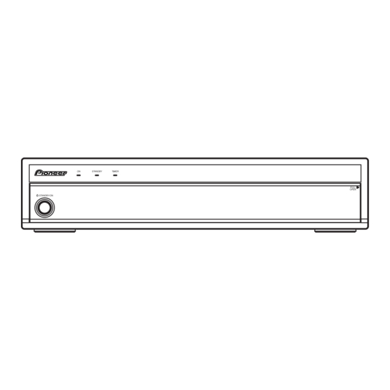
8. PANEL FACILITIES 8.1 PDP-R06XE Front view 1 POWER ON indicator 2 STANDBY indicator 3 TIMER indicator 4 STANDBY/ON button 5 INPUT button 6 VOLUME +/– buttons 7 CHANNEL +/– buttons 8 PC CARD slot 9 PC CARD EJECT button... - Page 108 TV/External input mode: Freezes a frame from a moving image. Press again to cancel the function. TELETEXT mode: Selects a page. 8 TV/DTV TELETEXT mode: Stops updating Teletext pages. Press again to release the hold mode. Switches between the TV and DTV input modes. PDP-R06XE...
-
Page 109: Pdp-R06Fe
3 i/o link.A SELECT switch 8 AUDIO OUTPUT termimals 4 INPUT 1 terminal (SCART) 9 INPUT 3 terminal (HDMI) 5 INPUT 2 terminal (SCART) 10 SYSTEM CABLE terminal (BLACK) 6 INPUT 3 terminal (SCART) 11 SYSTEM CABLE terminal (WHITE) 12 AC IN terminal PDP-R06XE... - Page 110 TV/External Input mode: Displays the Menu screen. Selects the TELETEXT mode. (all TV image, all TEXT image, TV/TEXT image) TELETEXT mode: Displays an Index page for the CEEFAX/FLOF format. Displays a TOP Over View page for the TOP format. PDP-R06XE...
- Page 111 PDP-R06XE...
- Page 112 • Before shipping out the product, be sure to clean the following positions by using the prescribed cleaning tools: Position to be cleaned Position to be cleaned Cleaning tools Cleaning tools Remark Remark Refer to "2.3 EXTERIOR SECTION" , "7.1.2 DISASSEMBLY SECTION". Fans Cleaning paper : GED-008 PDP-R06XE...