
Subscribe to Our Youtube Channel
Related Manuals for Samsung SN-S082D


Summary of Contents for Samsung SN-S082D
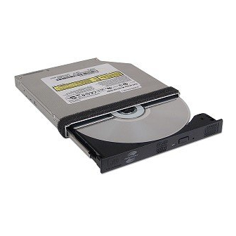
- Page 1 Service Manual Product Features DVD-W SLIM Product Features DVD-W SLIM READ The exterior design and some parts of the product may be changed without prior notification.
-
Page 2: Table Of Contents
Contents Contents Chapter 1 Safety Precautions Chapter 2 General Specifications and Features Chapter 3 Functional Description and Installation Chapter 4 Disassembly and Assembly Chapter 5 Troubleshooting Chapter 6 Block Diagram Chapter 7 Schematic Drawings... -
Page 3: Chapter 1 Safety Precautions
1. Safety Precautions 1-1. Safety Precautions for Repairs 1) Since the equipment uses laser diode, ensure 7) This equipment has many parts with properties that eyes and parts of the body do not come related to safety. These parts are specifically near the laser diode while performing repair noted in the parts list and schematic drawings. -
Page 4: Safety Precautions
1-3. Static Electricity, PL, and Voltage Safety Precautions 1) Read all safety and operational manuals before 11) Electrical Overload: Do not plug excessive number of operating the product. power cords into the outlet 2) Keep the safety and operational manuals for or extension outlet to prevent fire future reference. -
Page 5: Chapter 2 General Specifications And Features
2. General Specifications and Features 2-1. General Specifications - Drive Type: Internal DC +5V, 1.5A - Power Consumption: - Dimensions: 128(W) X 12.7(H) X 127(D) - Weight: 170g 2-2. Features - Interface: S-ATA - ACCESS TIME - Data Transfer Rate: - (CD-ROM) 1/3 Stroke: <... -
Page 6: Chapter 3 Functional Description And Installation
3. Functional Description and Installation 3-1. Hardware Functional Description Read CD-ROM: CAV 24X Max. CD-R: CAV 24X Max. CD-RW: CAV 24X Max. -
Page 7: Chapter 4 Disassembly And Assembly
4. Disassembly and Assembly 4-1. Disassembly 4-1-1. Exterior Components and PCB Disassembly CASE-TOP and ASSY PANEL FRONT Disassembly (a) Unscrew 3 Screws in the back by ejecting SET and pulling it forward. (b) Detach CASE TOP by pushing back and lifting up. (c) Detach COVER-DECK. - Page 8 ASSY-SOLENOID Disassembly (a) Unscrew 2 SCREWs in the bottom of ASSY TRAY. (b) Detach GUIDE GROUND. (c) Detach ASSY-SOLENOID from ASSY TRAY. ASSY PCB MAIN Disassembly (a) Unscrew 2 SCREWs in ASSY PCB MAIN. (b) Detach FPC MAIN by turning over ASSY PCB MAIN. (c) Detach ASSY PCB MAIN from ASSY TRAY.
- Page 9 ASSY-TRAY Disassembly (a) Detach it from ASSY CASE BOTTOM by pushing RAIL-LEFT. (b) Detach ASSY-TRAY.
- Page 10 4-1-4. Assembly Diagram...
- Page 11 - Parts List Name Specification S A-SNA Notes Part No. BG68-00945A LABEL RATING LABEL RATING; TS-L462C, DELL, ART PAPER, -, 8 BG61-00356A CASE-TOP CASE-TOP, ., AL, 0.5T, ., ., ., . BG92-00479A ASSY-PCB MAIN TS-L462C, - BG97-05170A ASSY-CASE BOTTOM ' -, TS-L462C, - BG97-03455A ASSY-TRAY ASSY-TRAY;...
-
Page 12: Chapter 5 Troubleshooting
5. Troubleshooting 5-1. Troubleshooting Procedure Checking the Power Supply and Initial Status After being plugged in, is the input status Check the connection of the of 5V and 12V normal? power short and cable. Check the power supply to CF101 and, Does CF101 oscillate? if necessary, replace it. - Page 13 No sled operation When you transfer the pick-up to the Replace Motor. outer cycle and turn the power on(Tray Eject), dose the P/U move to the inner one ? The below waveform is outputted in If the constant of IC102 and GND, pattern’s U10 125,126PIN ? when you check, replace.
- Page 14 No tray open/close operation Is the connector inserted Try again after a normal normally into the CN605? insertion of the connector into CN605. When the eject-switch is pressed, Check pattern and soldering of the does the voltage from the eject-switch IC609 connector. 13, 14pin of IC609 change from 0V? When the tray is close, is the 3.3voltage from the 53PIN of IC102 none ?
- Page 15 No laser diode on Is the connector inserted normally Try again after a normal insertion into the CON11? of the connector into CON11. Try again after replace of FFC Wire. Isn’t there any problem with the FFC Wire ? If the pattern of IC103 and soldering CN101ÀÇ...
- Page 16 Focus Lock does not function properly. After inserting CD DISC, is the Change IC102 if it is normal after checking the soldering, GND, wave emitted like below from Power of IC102. 124 PIN(F00) of IC102? Dose 14PIN of IC102 Power have 1.65V output? If the power of IC102 and GND, soldering is normal when you...
- Page 17 No spindle motor operation The below waveform is Check the power of U10, soldering and outputted in IC102 123PIN? replace of IC102. 1. DMSO Figure 2. U.V.W Figure Check the power of IC609, GND, soldering Do Pins 14(W),13(V), 12(U) show and replace of IC609.
- Page 18 5-2. Diagnostic Program 5-2-1. Environment A. Program: RW DIAG (FA TEST for Windows Program) B. Target Products: All ODD Products (CD-ROM, DVD-ROM, CD-RW, COMBO, DVD-WRITE) C. Evaluation Criteria and Test Specifications (a) CD-ROM, DVD-ROM Read Test (STD-200, TDV-520) < CD => 01:10 DVD => 02:05 Inner/Outer > - Sequential Read, Random Read 200 times on 10% of internal, external tracks (b) CD-R, CD-RW Write/Read Test (CD-R/RW) <CD-R=>00:50 CD-RW=>01:04 Inner/Outer >...
- Page 19 Using the Program The program automatically selects appropriate target test criteria for each product category to be evaluated, and test criteria that do not apply to the target evaluation products become inactivated so that they cannot be selected. Copy RWDIAG program supplied to hard drive . Connect the drive to be tested to the PC, and start the program.
- Page 20 DVD Writer. Check the status of Master/Slave pin setting. The PC does not recognize the Install the driver again, or go to Samsung Electronics website DVD Writer in DOS. (www.sec.co.kr) or to ODD Service website (www.samsung.ODD.com) to download and install the latest version of the driver.
- Page 21 5-4. Compatibility Issues and Suggested Actions What is DMA Mode? DAM (Direct Memory Access) allows autonomous transfer of data between the main memory and peripheral devices without CPU intervention which reduces the CPU load for multi-tasking, and increases the transfer speed. It minimizes the number of interrupts for inputs and outputs during program execution increasing system efficiency.
-
Page 22: Chapter 6 Block Diagram
6. Block Diagram Technical Assets - This document can not be used without Samsung's authorization. -
Page 23: Chapter 7 Schematic Drawings
7. Schematic Drawings Technical Assets - This document can not be used without Samsung's authorization. - Page 24 - Circuit Parts List SH-W162D(TS-H552D) Notes Name Part Number Specification SA-SNA 0904-002007 IC-DSP;MT1888E,16Bit,LQFP,216P,24.0x24.0 1003-001819 IC-MOTOR DRIVER;R2S30204FP,SSOP,42P,17.5 1105-001597 IC-DRAM;12L1616A,16BIT,TSOP,50P,400MIL,7 1107-001554 IC-FLASH MEMORY;M25P80,1Mx8Bit,SOP,16P,1 The parts list contains parts for SA only. Technical Assets - This document can not be used without Samsung's authorization.
- Page 25 - This manual is Samsung Electronics technical asset. Legal actions may be taken for unauthorized utilization if it is used for purposes other than the repair of Samsung Electronics products. © Samsung Electronics Co., Ltd. 11, 2005 Printed in Korea...
Need help?
Do you have a question about the SN-S082D and is the answer not in the manual?
Questions and answers