Bentone STG 146 Installation And Maintenance Instructions Manual
Hide thumbs
Also See for STG 146:
- Installation and maintenance instruction (58 pages) ,
- Manual (25 pages) ,
- Installation and maintenance instruction (52 pages)

Related Manuals for Bentone STG 146


Summary of Contents for Bentone STG 146
- Page 1 178 008 26-2 2016-02-01 Providing sustainable energy solutions worldwide Installation- and maintenance instruction STG 146...
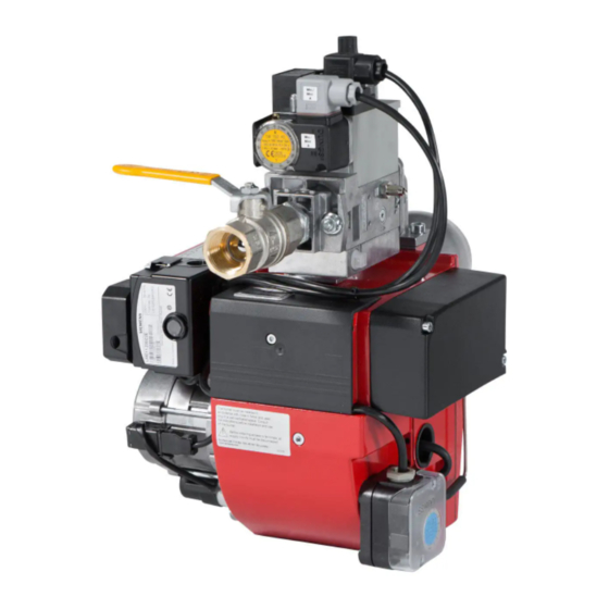
- Page 3 DESCRIPTION Components 1. Reset button 10. Ignition electrode 17. Air adjustment 2. Gas burner control 11. Air damper 18. Inner assembly adjustment 3. Transformer 12. Front part fan housing 19. Motor 4. Fixing flange 13. Rear part fan housing 20. Electric connection 5.
-
Page 4: Technical Data
TECHNICAL DATA Type designation STG 146 Burner head 1 in accordance with RAL UZ 80 Dimensions 23,5 109,5 145,0 Length of Flange A burner tube Measure A Standard Long design The above dimensions are max. measurements. Depending on the compo- nents used, the measurements may vary. - Page 5 TECHNICAL DATA Type designation STG 146 Burner head 2 Dimensions 23,5 109,5 145,0 Length of Flange A burner tube Measure A Standard 121,5 Long design 221,5 The above dimensions are max. measurements. Depending on the compo- nents used, the measurements may vary.
-
Page 6: Skeleton Diagrams
9. Air pressure switch Required over 1200 kW according cock 10. Gas burner control to EN 676. 5a. Gas pressure switch, mini 5b. Gas pressure switch, maxi When Bio gas is used, Bentone shall always be contacted. 172 415 11 07-01... -
Page 7: Mounting On The Boiler
MOUNTING ON THE BOILER Installation example Fit the enclosed flange and gasket to The gas armature is from the factory the boiler.If new fixing holes must be mounted in a horizontal position. The Connect the gas to the burner by drilled, use the fixing flange as a pat- connection of the incoming gas line means of the ball valve. -
Page 8: Electric Equipment
ELECTRIC EQUIPMENT Gas burner control: LGB21/LMG21/LME11/LME21 Wiring diagram If there is no plug-in contact (X2) on the boiler, connect to the contact enclosed. In case the twin thermostat is in series on incoming phase L1, a loop between the terminals T1 and T2 is necessary. - Page 9 ELECTRIC EQUIPMENT Control diagnosis under fault conditions and lockout indication Gas burner control: LGB Lock-out and Control Programme Indication The position of the cam can be read through the sight-glass. Under fault condition the programme is stopped and thus also the lock-out indicator. The symbol visible on the cam indicates both the position in the programme run and the type of fault.
- Page 10 ELECTRIC EQUIPMENT Control diagnosis under fault conditions and lockout indication Gas burner control: LMG ... Diagnosis of cause of fault After lockout, the red fault LED is steady on. For reading the cause of fault, refer to the blink code given in the following table: Press lockout reset button Red LED on LED on (waiting time≥10 s)
- Page 11 ELECTRIC EQUIPMENT Control diagnosis under fault conditions and lockout indication Gas burner control: LME..Colour codes Colour code table for multi-coloured signal lamps (Light diodes) Status Colour codes Colours ○………………… Waiting time «tw», other waiting times Ignition phase, ignition checked •○...
- Page 12 ELECTRIC EQUIPMENT Control diagnosis under fault conditions and lockout indication Gas burner control: LME... Alarm control table Red flashing code Possible causes on signal lamp (LED) Flashing 2 x • No flame at End of «TSA» •• – Defective or obscured flame monitor –...
- Page 13 MEASURES AND CHECKS BEFORE START-UP General rules Care should be taken by the installer to ensure that no electrical cables or fuel/gas pipes are trapped or damaged during installation or service/mainte- nance. Inner assembly Ensure that the ignition and ionisation electrodes are correctly adjusted.
- Page 14 MEASURES AND CHECKS BEFORE START-UP Inner assembly Town gas not CE approved Inner assembly Natural gas, LPG Natural gas Inner assembly Biogas (UV-detector) 172 205 77 07-01...
- Page 15 DETERMINATION OF GAS VOLUME FOR THE INSTALLATION Specifications on natural gas, town Net calorific value gas and bio gas vary. For more exact Gas quality kWh/Nm kJ/Nm kcal/Nm information please contact the gas Natural gas 10,3 37 144 8 865 distributor.
- Page 16 ADJUSTMENT OF MULTI-BLOC, MB-DLE 405-407 Flow adjustment Loosen the fixing screw a. Turn the hydraulic device b: to the right = the gas flow is reduced to the left = the gas flow is increased Do not forget to tighten the fixing screw again.
-
Page 17: General Instructions
GENERAL INSTRUCTIONS Adjustment of burner The adjustment of the position of the The burner is from the factory pre-set Open the ball valve and switch on the main switch. If the burner starts the brake plate affects the air flow. It is to an average value that must then actual adjustment can be made. - Page 18 GENERAL INSTRUCTIONS Adjustment of inner assembly Air adjustment Control of burner head 172 305 50 07-01...
-
Page 19: General Instruction
GENERAL INSTRUCTION Flame monitoring and measure- Adjustemnt of max. gas pressure Adjustment of air pressure switch ment of ionisation current switch The air presure switch should stop the The burner is monitored according The burner is equipped with a max. burner if the air volume is reduced. - Page 20 FINAL TEST OF THE INSTALLATION – Fault location, functional troubles Make repeated start attempts to ensure that the adjustments Trouble free operation is dependent function. on three factors: electricity, gas and air supply. Should there be any changes – Close the ball valve during in the ratio between these three factors operation to check that the gas there is a risk of break downs.
-
Page 21: Gas Burner
Fault location guide Gas burner The basis for a trouble free operation can only be ensured by the correct combined effect of the three factors: electricity, gas flow and combustion air. Should any of these factors change, troubles may arise. t has been proved that many troubles have rather simple causes. - Page 22 Cause Remedy No electrical connection through the air pressure switch Test the adjustment and the function of the air pres-sure switch. The starting load is not correctly adjusted Reduce or increase the gas supply, reduce the quanti ty of air. Gas relay defective Replace Air pressure switch incorrectly adjusted or defective...
- Page 23 Cause Remedy The burner is operating correctly but locking out now and then The ionisation current is too low Check. Must be at least 4 µ A according to the relay manufacturer but should be 8-20 µ A. The UV-cell is in a wrong position Adjust Voltage drop at certain times Must not drop more than 15% of the rated...
-
Page 24: Declaration Of Conformity
CE - märkningen. dessus, le brûleur recevra le marquage CE de conformité. Ljungby, Sweden, 141127 (27/11/14) Enertech AB Bentone Division is quality certified according to SS-EN ISO 9001 ENERTECH AB Bentone Division Enertech AB Bentone Division är kvalitetscertifierat enligt... -
Page 25: General Instructions For Gasburners
GENERAL INSTRUCTIONS FOR GASBURNERS Installation Follow standards and instructions applicable to the Check that the input pressure of the gas is correct installation of gas burners Check that the dampers of the boiler are open Ensure that the electric installation is made in Check that there is water in the system accordance with existing regulations Check that thermostats etc. - Page 26 SERVICE AND INSPECTION CARD Installation Boiler Name: Type: Efficiency kW: Address: Burner Type: Efficiency kW: Installed by: Date: Date gas/h Governor Flue gas Ionisa- Pressure Efficiency temp tion current Fire room Chimney Measure- Before After °C µ A mbar mbar % ment Small flame...
- Page 28 Enertech AB. P.O Box 309, SE-341 26 Ljungby. www.bentone.se, www.bentone.com...
Need help?
Do you have a question about the STG 146 and is the answer not in the manual?
Questions and answers