Table of Contents
Advertisement
INSTALLATION GUIDE
Guide for your AZ-125, Azimuth Drive Solar Tracker
Congratulations, you have purchased the finest solar tracker available. With proper installation, your tracker will
provide years of trouble-free service while maximizing your solar power production.
Your tracker may include one of the following options: (Check your packing slip.):
Stainless Steel Hardware Option - Recommended for high humidity and salt laden environments.
♦
Wattsun Voltage Converter Option - Required for PV Systems other than 24 VDC.
♦
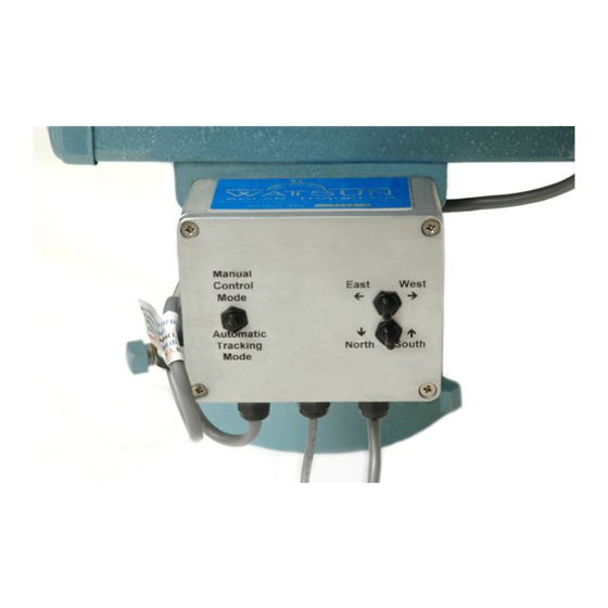
Manual Control Option - Exterior switches so you may manually operate the tracker.
♦
The tracker comes complete with all the hardware necessary for assembly and mounting the PV modules. The
Wattsun™ Tracker requires a length of Six-Inch ID Schedule 40 Steel Pipe for use as the pipe mast.
Specifications for the pipe mast can be found on the data sheet for this particular tracker. The steel mounting
pipe and PV modules are not included. Your electrician should provide all additional array wiring, fusing,
power disconnects, grounding equipment and electrical junction boxes.
If the Wattsun™ Azimuth Solar Tracker is not installed to manufacturer's specifications, such
failure to properly install unit may cause tracker malfunction and or serious bodily injury or
death. This tracker moves, therefore the tracker should be situated away from anybody or
anything that may come in contact with it as it moves.
KEEP CHILDREN AWAY FROM TRACKER AT ALL TIMES.
Array Technologies, Inc.
3312 Stanford NE
Albuquerque, NM 87107
WARNING:
Tel: 505-881-7567
Fax: 505-881-7572
URL:
www.wattsun.com
1
Advertisement
Table of Contents

Summary of Contents for Wattsun AZ-125
-
Page 1: Installation Guide
The tracker comes complete with all the hardware necessary for assembly and mounting the PV modules. The Wattsun™ Tracker requires a length of Six-Inch ID Schedule 40 Steel Pipe for use as the pipe mast. Specifications for the pipe mast can be found on the data sheet for this particular tracker. The steel mounting pipe and PV modules are not included. - Page 2 Copyright © Array Technologies, Inc. All rights reserved. Wattsun™ is a trademark of Array Technologies, Inc. AZ-125 Azimuth Gear Drive AZ-125 Azimuth Gear Drive Elevation Actuator for the Side View Front View Dual-Axis Option Wattsun Solar Tracker Controller Remote Sun Sensor that connects...
- Page 3 ♦ Do not rely on the pipe mast to act as a ground rod. It is not a reliable substitute for a properly installed ground rod. ♦ Please send in the Wattsun Tracker Warranty Card. Array Technologies does not share any of the information provided on the warranty card.
-
Page 4: Table Of Contents
Power Connection to the Elevation Actuator Power Connection to the Tracker Controller Operating the Tracker Controller Setting the Azimuth Drive Motor Limits W48-24 LVC: Pre-Regulator for 48 VDC PV Systems Manual Control Option Periodic Maintenance Suggested Grounding Methods for Wattsun Solar Trackers Warranty... -
Page 5: Installation Of The Tracker Pipe Mast And Foundation
1.4) Use the appropriate length of 6" ID, Schedule 40 Steel Pipe in order to leave the recommended maximum pipe mast height protruding from ground. Consult your specific Wattsun Technical Data Sheet for the appropriate mast height and pipe diameter size. Note: If the recommended pipe mast height is exceeded, it may be necessary to telescope a larger diameter pipe in the lower portion and increase the foundation size in order to withstand the increased forces exerted during windy conditions. -
Page 6: Install The Azimuth Gear Drive Assembly On Top Of The Pipe Mast
Locate ‘magnetic north’ or ‘magnetic south’ using a compass and adjust your tracker setting accordingly. Your Wattsun Tracker Dealer can provide you with the Magnetic Declination for your area. The Array Technologies web site (www.wattsun.com) has links to geomagnetic data. You can find, or calculate, the magnetic declination for any place on the globe. - Page 7 “lift handles.” You will damage the motor gearing or tracker controller if you put any unusual force on them. The AZ-125 Drive orientation is preset at the factory and referenced to Solar Noon. The drive should be mounted facing due South, (Due North in the Southern Hemisphere.).
-
Page 8: Install Single-Axis Bar Elevation Or Actuator
Install the AZ-125 SA Bar or Elevation Actuator THE AZ-125 DRIVE WEIGHS 130 to 145 LBS: You will have to be able to lift the AZ-125 Drive up, over and down on top of your mounting pole. Placing the drive on top of the pipe is at least a “two person” job. The drive is much easier to set using a boom and pulley arrangement or suspending it from a backhoe bucket or other appropriate method. - Page 9 ELEVATION ACTUATOR CONNECTIONS TO THE TRACKER DRIVE Do not unscrew the inner tube of the elevation actuator! This destroys the factory pre-set mechanical upper and lower limit switch settings. Install the elevation actuator. Center both the eyelet end (the top) of the elevation actuator inside the forks and the elevation actuator clamp eyelet (the bottom).
- Page 10 For either application, the web of the module mounting struts must be oriented toward the outer ends of the modules. AZ-125 HORIZONTAL TORQUE TUBE INSTALLATION Consult the diagrams below for the bolt connections. Tighten the U-bolt Nylock nuts to 70 Ft-Lbs of torque TIGHTEN NYLOCK 5/16”...
-
Page 11: Installing The Torque Tube & Module Support Frame Assembly
Each rail is U-bolted onto the horizontal “steel spine” of the tracker called a torque tube. If the rails are longer than ten feet then an additional support under-angle is included – one for each rail. Wattsun Trackers come with all the hardware to assemble the tracker and mount the modules. - Page 12 BUILDING THE FRAME AND RACKING THE MODULES: DO YOU MOUNT ONE PIECE AT A TIME OR BUILD SUB-ARRAYS? dule Rail & port bott om up the Procedure is: One installer, one piece at a time approach. Bolt > Support Angle > Tube > Rail >Washer > Nut Modules are being used to “square-up: the frame.
- Page 13 Each manufacturer has unique hole patterns. Your mounting holes are made to accommodate either 1/4” or 5/16” module mounting bolts. The bolts are supplied with your Wattsun Tracker. Step 2 Identify your module mounting bolts and nuts from the hardware kit. The module bolts are labeled and are either 1/4”...
- Page 14 Step 4 Measure and record the “center to center” distance of the intermediate mounting holes. This dimension sets the spacing of the mounting rails. Each pair of mounting rails typically holds from 3 to 4 large modules. Typical rail spacing might be from 24”...
- Page 15 Step 7 If you have a three column tracker (3 modules wide) then your first rail set will be centered over the drive head and straddle the centerline of the torque tube. If you have a four column tracker ( 4 modules wide) then your first rail set will be to the right or left of the centerline of the torque tube.
- Page 16 Step 10 Use a tape measure and gap the module rails a distance equal to the “center to center” intermediate hole spacing. (Step 4) Be sure that you are spacing from the centers of both top tracks in the rails. You might have to loosen the u-bolt Nylock nuts so that you can easily adjust the rail assembly along the torque tube.
-
Page 17: Installing The Tracker Controller
Controller input power specifications: The input voltage range is 23 to 50 volts DC. Use a Wattsun Voltage adapter to power the controller for nominal voltages other than 24 VDC. Tracker controller wiring and drive motor wiring: Do not connect the motor output wire harness to a power source! Connecting any of the controller output... - Page 18 WARNING! MAKE THE “POWER IN” CONNECTION LAST! DO NOT ENERGIZE THE WATTSUN SOLAR TRACKER CONTROLLER UNTIL YOU HAVE COMPLETED THE ENTIRE TRACKER INSTALLATION. THERE ARE TWO ADDITIONAL CONTROLLER CONNECTIONS THAT GET MADE BY THE INSTALLER: Sensor mounts on the top edge of the array.
- Page 19 WATTSUN TRACKER CONTROLLER: FUNCTION AND FEATURES. OVERVIEW Wattsun™ Solar Trackers utilize a patented, closed loop, optical sensing system to sense the sun’s position and track it. The sun sensors are mounted on the remote chassis and feed information to the control electronics about the direct component of sunlight available, the diffuse amount of sunlight, the total amount of sunlight as well as the differential amount of sunlight on opposing sensors.
- Page 20 Terminal Controller Output Motor White Azimuth Drive Green Azimuth Drive Elevation Actuator Black Elevation Actuator...
- Page 21 East-West Azimuth movement. The second pair (Red & Black) “passes through” and controls the North-South elevation movement. The Elevation Actuator power lead exits azimuth motor cover through the strain relief and will be connected to the actuator motor by the installer. AZ-125 AZIMUTH MOTOR WIRE CONNECTIONS...
- Page 22 AZIMUTH MOTOR: TERMINAL STRIP WIRING DIAGRAM (POWER CONNECTIONS ARE PREWIRED AT THE FACTORY) WARNING! THE LAST CONNECTION MADE IS FROM YOUR POWER SOURCE TO THE TRACKER CONTROLLER! DO NOT ENERGIZE THE WATTSUN SOLAR TRACKER CONTROLLER UNTIL YOU HAVE COMPLETED THE ENTIRE TRACKER INSTALLATION.
- Page 23 5.2) MOUNTING THE REMOTE SENSOR MOUNT THE REMOTE SENSOR ON THE TOP OF THE ARRAY The sensor mounts on the TOP CENTER (or near the center) of the PV array. Most modules already have a hole in the frame that you can use. If your modules do not have an "end hole" then you will need to drill a 1/4"...
-
Page 24: Power Connection To The Elevation Actuator
Section Power Connection to the Elevation Actuator Warning! Never apply power to the actuator until it has been securely bolted into place. The linear actuator will tend to "unscrew" and will destroy the preset limit switch settings. 6.1) Loosen the 4 cover screws and remove the actuator cover. The plastic strain relief might be inverted to protect it during shipping. -
Page 25: Power Connection To The Tracker Controller
NOTE: The azimuth-tracking limit switches are preset at the factory to accommodate the maximum range of East-West azimuth tracking. Array Technologies recommends that you power your Wattsun Tracker Controller from a battery bank or grid-tied power source. The tracker will return to the East at sunset and the tracker has 270 degrees of azimuth tracking available. - Page 26 If the installation is for a 48-volt system, then you should use a Wattsun Voltage Converter (Part# ♦ W48/24 HD or equivalent) to reduce the voltage to the tracker controller and motors.
- Page 27 CONTROLLER DIAGRAM, COMPONENTS, SWITCH SETTINGS AND FUSING Interior View of a Dual-Axis Controller for Azimuth Trackers DIP SWITCH SETTINGS Default Up Position Down Position Down Freeze Tracker - Temporary off only Normal: Auto Track Normal: Energy Integration ON: Energy Integration OFF: Lowers the voltage input threshold to power from a low state of Allow for low current sources to power the tracker controller.
-
Page 28: Operating The Tracker Controller
Setting Preferences and Operating Section the Tracker Controller OVERVIEW: OPERATING THE TRACKER CONTROLLER AND SETTING THE DIP SWITCH OPTIONS. Your tracker controller is preinstalled and “ready to go” as soon as you connect power it. The following procedure tests the controllers operation, the full range of motion of the tracker and to set some field selectable options. You can turn the tracker on and off or choose to bypass the Energy Integration Circuit. -
Page 29: Setting The Azimuth Drive Motor Limits
Section Setting the AZ Motor Limits KEEP YOUR FINGERS AND TOOLS AWAY FROM THE GEARING BENEATH THE PROTECTIVE COVER OF THE DRIVE! The limits for your tracker are preset at the factory. Please contact Array Technologies if you want to change your settings. - Page 30 Make your adjustments in small increments. And always Test the range of motion after making any adjustment! AZ-125 Gear Drive Do not exceed 135 degrees of rotation West of South or the Worm Gear Assembly will hit a welded safety stop. If you hit the stop the tracker motors will draw too much current and a self-resetting fuse in the controller will shut off the power to the azimuth motor.
-
Page 31: W48-24 Lvc: Pre-Regulator For 48 Vdc Pv Systems
♦ FUNCTION: The maximum voltage input for a standard Wattsun Tracker Controller is 50 VDC. PV arrays and battery banks that have a "working" voltage greater than 24 VDC nominal can exceed the 50 VDC threshold. The 48-24 LVC regulator limits the voltage input to the tracker controller to a maximum of 35 VDC. At 37 VDC and below, the actual operating voltage is 2 VDC lower than the input voltage. - Page 32 4-module, 48 VDC nominal string. 5) Open the Wattsun Solar Tracker Controller and set switch #2 to the UP (PV) Energy Integration setting. 6) Reconnect the main battery bank or PV array circuit so that power can flow through the voltage regulator and Wattsun Solar Tracker Controller.
-
Page 33: Manual Control Option
Array Technologies. However it is available as an upgrade kit that can be installed in the field. The Manual Control Option requires that power be available to the Wattsun Tracker Controller. If the controller is connected to the main battery bank, then you can use the manual controls day or night. If you power the tracker controller from the array, then you will be limited to the daylight hours. -
Page 34: Periodic Maintenance
Section Periodic Maintenance 12) PERIODIC MAINTENANCE Maintenance should be performed at least once a year. More often if your tracker is installed in severe ♦ weather areas. Inspect all the tracker hardware and the module bolts for tightness and tighten all nuts and bolts that need it. ♦... -
Page 35: Suggested Grounding Methods For Wattsun Solar Trackers
• Array Technologies does not assume any liability for your failure to adhere to the NEC. • Failure to ground your tracker may void your Wattsun Warranty and may result in damage to your Wattsun Solar Tracker Controller or motors. - Page 36 FIG 1: GROUNDING THE MODULES, TRACKER FRAME, DRIVE AND MOUNTING PIPE The array equipment-grounding conductors, for the modules, tracker frame, drive and mounting-pipe, should terminate at one location—probably a grounding terminal strip in the junction/combiner box. Then, there should be a conductor from this point to the grounding electrode (ground rod).
- Page 37 FIG 2: TYPICAL GROUNDING OF A TRACKER TO THE BATTERY BANK/POWERCENTER. The modules, Wattsun Tracker, and mounting pipe are grounded as shown in Figure 1. • The normal, (primary bond) negative-to-ground bonding is required in the power center or ground-fault •...
- Page 38 ALTERNATIVE GROUNDING FOR A TRACKER THAT IS DISTANT FROM THE BATTERY BANK/POWERCENTER. The modules, Wattsun Tracker, and mounting pipe are grounded as shown in Figure 1. • The PV array is ground mounted some distance (perhaps over 30 feet) away from other PV components •...
-
Page 39: Warranty
Array Technologies, Inc. warrants its Wattsun™ Solar Trackers to the original consumer purchaser that it will repair, or replace, at Array Technologies Inc.’s option, any Wattsun™ Tracker component that is determined to be defective in material or workmanship for the following terms: Two years from date of purchase on all components including tracker controller, frame, azimuth drive assembly, and actuator.
Need help?
Do you have a question about the AZ-125 and is the answer not in the manual?
Questions and answers