
Related Manuals for doble SFRA


Summary of Contents for doble SFRA
- Page 1 Sweep Frequency Response Analyzer (SFRA) User Guide Doble Engineering Company 85 Walnut Street Watertown, Massachusetts 02472-4037 (USA) www.doble.com 72A-2570-01 Rev. K 07/2011...
- Page 2 WITHOUT LIMITATION, PERSONAL INJURY OR PROPERTY DAMAGE, ANY INCIDENTAL OR CONSEQUENTIAL DAMAGES, EXPENSES, LOST PROFITS, LOST SAVINGS, OR OTHER DAMAGES. Doble warrants the disks on which the software product is furnished to be free Software Limited Warranty from defects in materials and workmanship under normal use for a period of one hundred and twenty (120) days from the date of shipment from Doble.
- Page 3 DEALER) ASSUMES ALL LIABILITY ASSOCIATED WITH THE SOFTWARE AND THE ENTIRE COST OF ALL NECESSARY SERVICING, REPAIR, OR CORRECTION. If Doble notifies Purchaser that is unable to deliver replacement disks which Limitations of Remedies are free from defects in materials and workmanship, Purchaser may terminate this agreement.
- Page 4 Legend Intellectual This Manual is solely the property of the Doble Engineering Company (Doble) and is provided for the exclusive use of Doble clients under Property Notice contractual agreement for Doble test equipment and services. This Manual is protected by copyright, all rights reserved. No part of this book...
-
Page 5: Table Of Contents
Short Circuit ........................... 3-1 Step 1: Set Up and Run a Shorted-lead Test ................3-2 Connect the Cable and Leads and Run SFRA 5.2..............3-2 Create a Transformer Listing and Associate a Test Template with It........3-4 Run the Shorted-lead Test ...................... 3-8 Step 2: Ground the Transformer.................... - Page 6 Adding or Deleting SFRA Instrument Information..............5-3 Adding or Deleting Organization Information ................5-4 Managing Transformer Information ..................... 5-5 Entering a Transformer into the SFRA Database..............5-5 Editing or Deleting Transformer Data..................5-6 Cloning a Transformer ......................5-6 Importing and Exporting Transformer Files................5-7 Managing Tap Changer Data......................
- Page 7 Export Selected Results to .CSV Files ................. 5-10 Import Location and Transformer from Results Files............5-11 Saving and Deleting Traces ....................5-11 Importing 1.x and 2.x M5100 SFRA Files................5-12 Transferring Data between Machines or PCs............... 5-12 Settings Files ........................5-12 Merging Settings Files ......................
- Page 8 Three-Winding Transformers ...................... B-4 C. Theory of Operation ................C-1 Transformer Damage and SFRA Testing ..................C-1 How SFRA Identifies Damage to Transformers ................. C-2 Test Cable Lengths ........................C-4 Transformer ..........................C-5 D. Repairs and Replacement Parts ............D-1 Replacing a Fuse..........................
-
Page 9: List Of Figures
M5200, M5300, and M5400 Instruments ............. 1-2 Figure 2.1 Connecting Safety Ground to Transformer............2-2 Figure 3.1 Cable and Lead Connections to the SFRA Instrument ......... 3-2 Figure 3.2 Connect to Instrument Message................3-3 Figure 3.3 Select Instrument Window..................3-3 Figure 3.4... - Page 10 Sweep Frequency Response Analyzer (SFRA) User Guide Figure 3.31 Test Selection Window ..................3-19 Figure 3.32 Location of Start Test Button ................3-20 Figure 3.33 Test Details Window................... 3-20 Figure 3.34 Nonstandard Test Warning ................. 3-21 Figure 3.35 Test Details Dialog Box with Advanced Test Protocol ........3-21 Figure 3.36 Alert 952......................
- Page 11 List of Figures Figure A.4 Progress Bar in Installation Window ..............A-3 Figure A.5 Identifying an M5300 ..................A-4 Figure A.6 Select Default Template Window................ A-4 Figure A.7 Plot Property Dialog Box................... A-10 Figure A.8 Data Manager Tab....................A-11 Figure A.9 Magnitude Tab ....................
- Page 12 Sweep Frequency Response Analyzer (SFRA) User Guide 72A-2570-01 Rev. K 07/2011...
-
Page 13: List Of Tables
List of Tables Table 1.1 M5200, M5300, and M5400 Instruments ............. 1-2 Table 1.2 Accessories for the SFRA Instruments ..............1-3 Table A.1 File Menu Options ....................A-6 Table A.2 Edit Menu Options ....................A-6 Table A.3 Test Init Menu Options ..................A-7 Table A.4... - Page 14 Sweep Frequency Response Analyzer (SFRA) User Guide 72A-2570-01 Rev. K 07/2011...
-
Page 15: Preface
Preface The Sweep Frequency Response Analyzer User Guide explains how to install, configure, and operate Doble’s M5200, M5300, and M5400 Sweep Frequency Response Analyzer instruments. Who Should Read This Guide This guide is intended for engineers and field testers who work with an M5200, M5300, or M5400 Sweep Frequency Response Analyzer. - Page 16 Sweep Frequency Response Analyzer (SFRA) User Guide Cautions CAUTION! Cautions provide information that prevents damage to hardware or data. Warnings WARNING! Warnings tell you how to prevent injury or death to anyone near the test set or high-voltage equipment. 72A-2570-01 Rev. K 07/2011...
-
Page 17: Introduction
“PC Requirements” on page 1-4 M5200, M5300, and M5400 SFRA Instruments Sweep Frequency Response Analysis (SFRA) testing is a nonintrusive way to identify mechanical changes inside a transformer. Changes in the internal configuration produce different frequency responses that indicate a range of failure modes. -
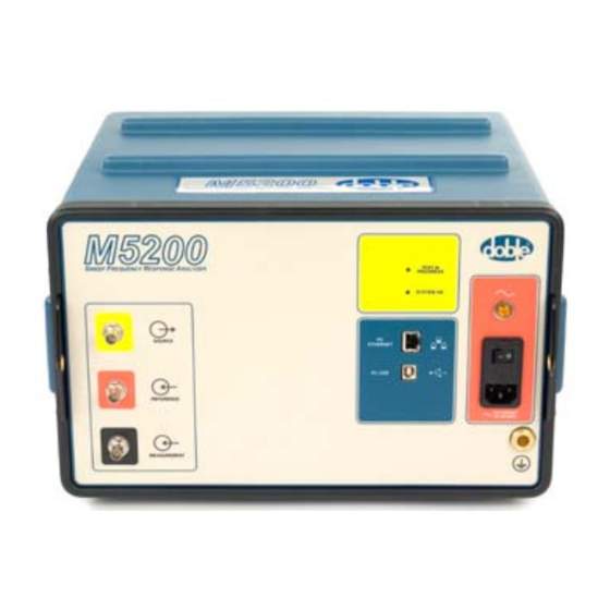
Page 18: Figure 1.1 M5200, M5300, And M5400 Instruments
Sweep Frequency Response Analyzer (SFRA) User Guide Table 1.1 M5200, M5300, and M5400 Instruments Name Description Image M5200 Requires an external laptop. Testing functions are identical to those of the M5300 and M5400. M5300 Has a built-in laptop, keyboard, and display. -
Page 19: Hardware Accessories
1. Introduction Hardware Accessories Table 1.2 describes the standard hardware accessories that come with the M520, M5300, and M5400. It also lists an optional test lead. Table 1.2 Accessories for the SFRA Instruments Item Description Part No. Test Leads Standard lead... -
Page 20: Software
Software The M5200 and M5400 are controlled by a user-supplied laptop computer running Doble SFRA software (supplied with the instrument). The M5300 comes with a built-in PC, laptop keyboard, and preinstalled Doble SFRA software. PC Requirements To see the minimum requirements for the PC used with the M5200 or M5400, please go to “PC Requirements”... -
Page 21: Safety
SFRA instrument. 2. The method of testing a high-voltage apparatus (transformer) involves exciting the apparatus with the SFRA instrument. Take care to avoid contact with the apparatus being tested, its associated bushings and conductors, and the SFRA instrument’s cables and connectors. -
Page 22: Grounding Requirements
Personal protective equipment suitable for electrical testing of transformers is recommended. Grounding Requirements The apparatus under test, its tank or housing, and the SFRA instrument must be solidly and commonly grounded or earthed. This also applies to any mobile equipment being tested. -
Page 23: Personnel Safety Practices
2. Safety Personnel Safety Practices Make sure that test personnel follow these recommendations: 1. A pretest meeting is recommended. Frequently, other crews will be working on non-test-related tasks in close proximity to equipment being tested. The pretest meeting should include all personnel who will be working in proximity to the area where testing will be performed. - Page 24 Sweep Frequency Response Analyzer (SFRA) User Guide 72A-2570-01 Rev. K 07/2011...
-
Page 25: Setting Up And Running A Test
HV terminals to neutral, such as X1 to X0. Short Circuit A short-circuit measurement is made with the same SFRA test lead connections as an open-circuit measurement, but with the difference that another winding is short- circuited. To ensure repeatability, Doble recommends that the three voltage terminals on the shorted winding be shorted together. -
Page 26: Step 1: Set Up And Run A Shorted-Lead Test
• M5300—Power up the M5300 and go to “Create a Transformer Listing and Associate a Test Template with It” on page 3-4. 2. Power up the PC. Run the SFRA program by double-clicking the icon or selecting... -
Page 27: Figure 3.2 Connect To Instrument Message
3. Setting Up and Running a Test Figure 3.2 Connect to Instrument Message 3. Turn on the SFRA instrument and wait 20 seconds. During this time: a. The power light comes on. b. The Test in Progress and System OK indicator lights come on. -
Page 28: Create A Transformer Listing And Associate A Test Template With It
Figure 3.4 Data Manager Tab on Main Window Create a Transformer Listing and Associate a Test Template with It NOTE: If the shorted-lead test has already been set up in SFRA 5.2, skip this section and go to “Run the Shorted-lead Test” on page 3-8. -
Page 29: Figure 3.5 Edit Apparatus Option On Edit Menu
Select a test template at random and associate it with the Leads transformer To create a dummy transformer and associate a test template with it: 1. In the main window of the SFRA software, open the menu and select Edit (Figure 3.5). -
Page 30: Figure 3.7 Transformer Tab Of Transformer Editor Window
Sweep Frequency Response Analyzer (SFRA) User Guide Figure 3.7 Transformer Tab of Transformer Editor Window 3. Click (Figure 3.7). The New Serial Number listing is highlighted (Figure 3.8). Figure 3.8 New Serial Number Listing 4. Enter in the Manufacturer field. -
Page 31: Figure 3.9 Test Templates Tab Of Transformer Editor Window
3. Setting Up and Running a Test Figure 3.9 Test Templates Tab of Transformer Editor Window 7. Click (#2 in Figure 3.9). Select The Template Editor window appears (Figure 3.10). Figure 3.10 Template Editor Window 8. Select any test template in the Template list and click 9. -
Page 32: Run The Shorted-Lead Test
Sweep Frequency Response Analyzer (SFRA) User Guide Run the Shorted-lead Test To run the shorted-lead test: 1. In the main SFRA window, click Select Apparatus The Apparatus Selection window appears (Figure 3.11). Figure 3.11 Apparatus Selection Window 2. Select in the Manufacturer column and click Leads 3. -
Page 33: Figure 3.13 Test Details Window
3. Setting Up and Running a Test The Test Details window appears (Figure 3.13). Figure 3.13 Test Details Window 4. Short the red source lead and black measurement lead by connecting the clamps to each other (Figure 3.14). CAUTION! Do not connect the measurement clamps to the ground clamps! 5. -
Page 34: Figure 3.15 Shorted-Lead Test In Progress
Sweep Frequency Response Analyzer (SFRA) User Guide 6. Click Run Test The Magnitude tab appears (#1 in Figure 3.15) and displays the trace as it develops. The Legend pane appears (#2) and a progress bar expands as the test progresses (#3). -
Page 35: Figure 3.16 Correct Shorted-Lead Response
3. Setting Up and Running a Test Figure 3.16 Correct Shorted-lead Response If the result resembles Figure 3.17, examine the leads for an open circuit. The open-circuit response is clearly affected by noise. Figure 3.17 Open-Circuit Lead Response 72A-2570-01 Rev. K 07/2011 3-11... -
Page 36: Step 2: Ground The Transformer
“Step 2: Ground the Transformer” on page 3-12. Step 2: Ground the Transformer Each time the SFRA test leads are connected, disconnected, or moved, apply temporary static-discharge grounds to: • The bushings to which the SFRA test clamps will be applied •... -
Page 37: Figure 3.20 Removed Isophase Or Gis Link
3.20). Figure 3.20 Removed Isophase or GIS Link 4. Apply temporary static-discharge grounds (Figure 3.21). Figure 3.21 Added Temporary Static-Discharge Grounds 5. Attach the SFRA test leads (Figure 3.22). SFRA Instrument Figure 3.22 Connected SFRA Leads 72A-2570-01 Rev. K 07/2011... -
Page 38: Step 3: Prepare The Transformer For Testing
Sweep Frequency Response Analyzer (SFRA) User Guide 6. Remove temporary static-discharge grounds (Figure 3.23). SFRA Instrument Figure 3.23 Removed Temporary Static-Discharge Grounds 7. Isolate terminals not under test and ensure that they are floating, unless otherwise specified in the test template. -
Page 39: Step 4: Select And Run A Test
By running the shorted-lead test, you have already followed the complete procedure for running a test. This section provides a testing procedure for a transformer that has already been set up in SFRA and associated with a test template. Requirements for This Test Complete these actions before you run a test: 1. -
Page 40: Figure 3.25 Test Equipment Editor
Sweep Frequency Response Analyzer (SFRA) User Guide Figure 3.25 Test Equipment Editor 2. Click the button on the right. Edit Transformers The Transformer Editor window opens, displaying the Transformer tab (Figure 3.26). Figure 3.26 Transformer Tab of Transformer Editor Window 3-16 72A-2570-01 Rev. -
Page 41: Figure 3.27 Test Templates Tab Of Transformer Editor Window
3. Setting Up and Running a Test 3. Click the (Figure 3.27). Test Templates Figure 3.27 Test Templates Tab of Transformer Editor Window 4. Click Select The Template Editor window appears (Figure 3.28). Figure 3.28 Template Editor Window 5. Select the template in the Template list and click 72A-2570-01 Rev. -
Page 42: Sfra Test Procedure
Transformer Editor window, and click Save to close the Test Equipment Editor. and Exit SFRA Test Procedure To run an SFRA test on a transformer: 1. In the main SFRA window, click Select Apparatus The Apparatus Selection window appears (Figure 3.29). -
Page 43: Figure 3.30 Location Of Select Test Button
3. Setting Up and Running a Test 3. In the Apparatus and Test pane, click (Figure 3.30). Select Test Figure 3.30 Location of Select Test Button The Test Selection window displays the tests contained in the template (Figure 3.31). Figure 3.31 Test Selection Window 72A-2570-01 Rev. -
Page 44: Figure 3.32 Location Of Start Test Button
Sweep Frequency Response Analyzer (SFRA) User Guide 4. Click (Figure 3.32) Start Test Figure 3.32 Location of Start Test Button The Test Details window appears (Figure 3.33). Figure 3.33 Test Details Window 5. Following the directions under the Red Lead Location and Black Lead Location headings in the template, connect the test leads and enter notes if required. -
Page 45: Figure 3.34 Nonstandard Test Warning
3. Setting Up and Running a Test 6. Do one of the following: • To perform a nonstandard test, go to step • To perform a standard template test, skip to step 10 on page 3-22. 7. To perform a nonstandard test, select the check box in Advanced Setup the Test Details window... -
Page 46: Self-Test Error And Warning Messages
“Self-Test Error and Warning Messages” on page 3-22. Self-Test Error and Warning Messages The SFRA self-test can produce the following error and warning messages: • Error 950—Internal temperature exceeds acceptable limits. M5000 instruments are designed to operate in a 50° C/ 122° F environment for extended periods. -
Page 47: Figure 3.37 Error 953
This signal verification test confirms that the device is performing as expected. If the test fails, results will be compromised. You are not allowed to continue the test. Contact Doble Engineering for troubleshooting and repair. 72A-2570-01 Rev. K 07/2011... -
Page 48: Troubleshooting Test Results
When the test finishes, the view auto-zooms so that the trace takes up most of the graph. Troubleshooting Test Results SFRA is an easy test to perform, but simple problems can occur during a test. These have characteristic signatures, as described below. Monitoring Waveforms The instrument allows you to monitor the reference and measured waveforms as you run through a test. -
Page 49: Diagnosing Open-Circuit Response
3. Setting Up and Running a Test Diagnosing Open-Circuit Response An open-circuit response may be caused by the black test lead dropping off the bushing, a poor connection, or damage within the test lead. The discrete change in the lower frequency range in Figure 3.39 on page 3-25 shows typical open-circuit behavior: about –90 to –100 dB. -
Page 50: Figure 3.40 Responses For One Phase Of A Transformer Hv Delta Trace
Sweep Frequency Response Analyzer (SFRA) User Guide Short Circuit Open Circuit LV Open Circuit HV Figure 3.40 Responses for One Phase of a Transformer HV Delta Trace Figure 3.41 shows the responses for three phases of a HV delta winding. This is a characteristic response at low frequencies: •... -
Page 51: Hv Wye (Star) Response
3. Setting Up and Running a Test HV Wye (Star) Response Figure 3.42 shows a typical HV wye (star) winding response. All three phases show similar responses at low frequencies, with the following characteristics: • The center phase has a slightly increased impedance (more negative dB) at low frequencies. -
Page 52: Figure 3.43 Short-Circuit Test Trace
Sweep Frequency Response Analyzer (SFRA) User Guide Figure 3.43 Short-Circuit Test Trace Even when responses are shown in magnification (Figure 3.44), they are under the average divergence of 0.2 dB among phases. This is a useful diagnostic where no previous results are available. -
Page 53: Repeat Results For One Phase At Different Times
3. Setting Up and Running a Test Repeat Results for One Phase at Different Times The two responses in Figure 3.45 were taken 18 months apart. The original data was taken as a baseline set of results; the subsequent data was taken after an incident involving the transformer. -
Page 54: Confirming The Ethernet Connection
Sweep Frequency Response Analyzer (SFRA) User Guide Figure 3.46 shows an example of a shorted turn on one winding. Figure 3.46 Shorted Turn on One Winding Confirming the Ethernet Connection To confirm that the PC is connected to the instrument using the Ethernet connection: 1. -
Page 55: Figure 3.48 Command Window Displaying Ip Address
Figure 3.48): • enet.m5200—This suffix confirms that the instrument is connected to the PC. If SFRA still cannot find the M5000 instrument, contact your Doble representative for assistance. • Anything else—Any other suffix indicates that instrument is not communicating with the PC. Check the cable connections. If this does not solve the problem, you may want to contact your IT department for assistance with network connections. - Page 56 Sweep Frequency Response Analyzer (SFRA) User Guide 3-32 72A-2570-01 Rev. K 07/2011...
-
Page 57: Managing Tests And Templates
4. Managing Tests and Templates This chapter describes the templates provided with SFRA 5.2 and explains how to use them. It contains the following sections: • “Introduction” on page 4-1 • “Opening the Template Editor” on page 4-1 • “Creating a New Test Template” on page 4-2 •... -
Page 58: Creating A New Test Template
Sweep Frequency Response Analyzer (SFRA) User Guide Figure 4.1 Template Editor Creating a New Test Template To create a new test template: 1. In the Template Editor window, click A New Template appears in the Template List. 2. Enter a name in the Name field (required) and a description if desired. -
Page 59: Editing Or Deleting A Template
4. Managing Tests and Templates Figure 4.2 Test Setting Editor 4. Enter the appropriate settings. Red Lead and Black Lead are required. 5. Click Editing or Deleting a Template To edit or delete a test template: 1. In the Template Editor window, select the template from the Template List. -
Page 60: Creating A New Test Setting
Sweep Frequency Response Analyzer (SFRA) User Guide 2. Click the button. Edit Templates The Template Editor window opens. 3. Click Manager The Test Setting Editor window opens (Figure 4.2 on page 4-3). The name of each available test appears in the Test Setting List. The minimum required information is the position of the red lead (e.g., H1, A,... - Page 61 SFRA enables you to add or delete location data, and to export or import location files. To manage location information: 1. In the main window of the SFRA software, open the Edit menu and select Edit Apparatus . The Test Equipment Editor window opens (Figure 5.1 on page...
-
Page 62: Figure 5.1 Test Equipment Editor
Select and delete these words in the Location field and type in the new location. Figure 5.2 Entering a New Location SFRA software enables you to import and export Location files. This helps ensure consistency of locations for different users. 72A-2570-01 Rev. K 07/2011... -
Page 63: Managing Data And Generating Reports
6. Save all changes by clicking Save and Exit . Adding or Deleting SFRA Instrument Information The Test Equipment List displays the serial numbers of Doble SFRA instruments that have been added into the SFRA database. To add a serial number: 1. -
Page 64: Adding Or Deleting Organization Information
The organization is the owner of the transformer to be tested. To add organization information in this window: 1. In the main window of the SFRA software, open the Edit menu and select Edit Apparatus . The Test Equipment Editor window opens (Figure 5.1 on page... -
Page 65: Managing Transformer Information
The Transformer Editor enables you to create, edit, review, and delete detailed information about transformers. To add or edit transformer information: 1. In the main window of the SFRA software, open the Edit menu and select Edit Apparatus . The Test Equipment Editor window opens (Figure 5.1 on page... -
Page 66: Editing Or Deleting Transformer Data
Sweep Frequency Response Analyzer (SFRA) User Guide 2. Select a manufacturer from the drop-down menu on the Transformer tab. This is a required field. If the manufacturer name is not available, select No MFR Listed 3. Enter the serial number of the transformer. This is a required field. Each transformer must have a unique serial number;... -
Page 67: Importing And Exporting Transformer Files
4. Make any other necessary edits on the Transformer Editor tabs. 5. Click Importing and Exporting Transformer Files SFRA software allows you to import and export Transformer files. This helps ensure consistency for different users. The files are saved in .XML format. To export a transformer file: 1. -
Page 68: Managing Results Data
Sweep Frequency Response Analyzer (SFRA) User Guide Figure 5.7 LTC/DETC Tab of Transformer Editor Window Managing Results Data This section explains how to store, export, and import data; transfer data files between machines; work with settings files; and configure and generate reports. -
Page 69: Selecting A Data Source
5. Managing Data and Generating Reports Figure 5.8 Sweep Frequency Response Analyzer Settings Dialog Box To change the location of a data folder or template file: 1. Select Edit Options The Sweep Frequency Response Analyzer Settings dialog box (Figure 5.8) appears. -
Page 70: Export Selected Results To .Csv Files
6. Click the plus sign to the left of a category in the Data Tree to display the options for viewing a subset of data in that category. Click if you select a new data source or add SFRA Refresh Data Tree traces to the default folder while the software is open. -
Page 71: Import Location And Transformer From Results Files
5-8. If the test is canceled, the data is not saved. The SFRA software has no Delete option. To delete files, locate the file using the time-stamp in the folder where it is stored and delete it in Windows Explorer. The filename appears as the last column of each row in the Data Manager tab. -
Page 72: Importing 1.X And 2.X M5100 Sfra Files
You can import data from M5100 versions 1.x and 2.x software by placing those files in the appropriate data source location. When opened, they will be parsed for content, converted to the new Doble SFRA format, and renamed with a different extension so as not to be reconverted subsequently. Be sure to back up copies of these files as a precaution against data loss. -
Page 73: Figure 5.11 Simplified Xml Transformer Settings File
5. Managing Data and Generating Reports Figure 5.11 displays a simplified view of a Transformer settings file that will be used to describe the file in detail. Line # XML Code <?xml version="1.0" encoding="utf-8"?> <transformerNameplates> <transformerNameplate version="1"> <manufacturer>ABB</manufacturer> <serialNumber>1234</serialNumber> </transformerNameplate> <transformerNameplate version="1">... -
Page 74: Merging Settings Files
The manual merge described here is prone to cut-and-paste errors. Back up all data and settings files before performing a merge operation. The following example concerns two SFRA users who want to share XML files. Figure 5.12... -
Page 75: Figure 5.13 Transformer Settings File - User B
5. Managing Data and Generating Reports Figure 5.13 shows another simplified transformer settings file, this one from User B: <?xml version="1.0" encoding="utf-8"?> <transformerNameplates> <transformerNameplate version="1"> <manufacturer>ACME</manufacturer> <serialNumber>9999</serialNumber> </transformerNameplate> </transformerNameplates> Figure 5.13 Transformer Settings File — User B User A’s file contains two transformers (underlined in the tables for clarity): •... -
Page 76: Reports
Windows Explorer. Reports The Reports feature of SFRA provides a variety of options that enable you to include only the information types you want. To configure and print a report: 1. -
Page 77: Figure 5.15 Report Designer Window
5. Managing Data and Generating Reports Figure 5.15 Report Designer Window 3. Select the report options you prefer and do any of the following: • Click . This saves the selections you have made in Save this Design the Report Designer window and applies them to any report you create in the future. - Page 78 Sweep Frequency Response Analyzer (SFRA) User Guide 5-18 72A-2570-01 Rev. K 07/2011...
-
Page 79: A. Software Overview
A. Software Overview This appendix explains how to install SFRA 5.2 and the appropriate USB driver and provides a complete overview of the SFRA 5.2 user interface. It contains the following sections: • “Installing SFRA 5.2” on page A-1 •... -
Page 80: Figure A.1 Welcome Window Of Setup Wizard
4. Make the following selections: • Accept the default folder or browse to a folder of your choice. • Choose if you are installing SFRA on your personal Just Me computer. • Choose if you are installing SFRA on a general-use Everyone machine. -
Page 81: Software Overview
A. Software Overview 5. Click Next The Confirm Installation window appears (Figure A.3). Figure A.3 Confirm Installation Window 6. Review your installation choices and go back to change them or click Next to confirm them. A progress bar appears (Figure A.4). -
Page 82: Figure A.5 Identifying An M5300
Sweep Frequency Response Analyzer (SFRA) User Guide 8. Run SFRA 5.2 by double-clicking the icon on the desktop or running the program from within the Start menu. A message window asks whether your instrument is an M5300 (Figure A.5). Figure A.5 Identifying an M5300 9. -
Page 83: Manually Install The Usb Driver
A. Software Overview Manually Install the USB Driver It is crucial that you manually install a specific USB driver for your SFRA instrument. Do not rely on any pre-installed drivers that came with Windows. Where to Find the Driver Made by Silicon Laboratories, the USB driver can be found in these locations: •... -
Page 84: Sfra 5.2 Software Overview
Sweep Frequency Response Analyzer (SFRA) User Guide SFRA 5.2 Software Overview This section provides a complete reference of all SFRA software controls. To find a control, look it up in the following tables by its physical location in the user interface, or look it up in the Index of this manual to find the page number. -
Page 85: Test Init Menu
A. Software Overview Test Init Menu Table A.3 lists and describes the Test Init menu options. Table A.3 Test Init Menu Options Command Description Select Apparatus Opens the Apparatus Selection dialog box, enabling you to select an apparatus for a test. Start Test Starts a test. - Page 86 Sweep Frequency Response Analyzer (SFRA) User Guide Table A.4 Graph Menu Options (Continued) Command Description Zoom Zooms on the graph section between cursor positions. Both cursors must be visible. Shortcut key: Shift + click. You can also shift, click, and drag diagonally to create a rectangle outlining the area you want to zoom on.
-
Page 87: Help
A. Software Overview Table A.4 Graph Menu Options (Continued) Command Description Clear Traces Opens the Clear Traces dialog box, allowing you to remove one or more traces from the display. Check the boxes of the traces you wish to remove and click Clearing traces is different from... -
Page 88: Apparatus/Test And Legend Panes
Sweep Frequency Response Analyzer (SFRA) User Guide Apparatus/Test and Legend Panes Click the appropriate tab at the lower left of the main SFRA window to display the Apparatus/Test pane and the Legend pane. Apparatus and Test Pane Use the Apparatus and Test pane at the left of the main screen to select a transformer for test, set basic test parameters, and start a test. -
Page 89: Tab Divisions In Sfra
A. Software Overview Tab Divisions in SFRA This section describes the main tab divisions of the SFRA 5.2 user interface. Data Manager Tab The Data Manager tab (Figure A.8) displays test files grouped by folders (default or user-defined), with controls to select, display, and export those files. -
Page 90: Magnitude Tab
Sweep Frequency Response Analyzer (SFRA) User Guide Magnitude Tab The Magnitude tab (Figure A.9) displays magnitude versus frequency for the selected graph(s). Figure A.9 Magnitude Tab Figure A.10 shows the status bar at the bottom of the main screen. The coordinates reflect the last change you made to the cursor position on any of the three tabs. -
Page 91: Phase Tab
A. Software Overview Phase Tab The Phase tab (Figure A.11) displays phase versus frequency for the selected graph(s). Phase is rarely used but can occasionally be useful when looking at whether a measurement is more inductive or more capacitive. Figure A.11 Phase Tab Figure A.12 shows the status bar at the bottom of the main screen. -
Page 92: Impedance Tab
Sweep Frequency Response Analyzer (SFRA) User Guide Impedance Tab The Impedance tab (Figure A.13) displays Impedance (Z ohms) and Admittance (Y Mhos) representations, using the magnitude and phase results for calculation. Use the option button at the lower left to select the desired display type. -
Page 93: Sub-Band Tab
The Sub-Band tab (Figure A.15) is included for historical continuity. Early work on SFRA required results displayed on graphs of 2 kHz, 20 kHz, 200 kHz, and 2 MHz. The last three of these are included here to permit viewing those graphs. -
Page 94: Waveform Tab
Sweep Frequency Response Analyzer (SFRA) User Guide Waveform Tab The Waveform tab (Figure A.16) is useful when monitoring the progress of a measurement: it displays both the reference waveform generated by the test set and the measured waveform of the object under test. This tab displays a waveform only when a test is in progress. -
Page 95: Analysis Tab
A. Software Overview Analysis Tab The Analysis tab (Figure A.17) enables you to compare two traces. The upper pane displays the two traces you select; the lower pane displays the difference between them. Figure A.17 Analysis Tab 72A-2570-01 Rev. K 07/2011 A-17... -
Page 96: Tabulation Tab
Sweep Frequency Response Analyzer (SFRA) User Guide Tabulation Tab The Tabulation tab (Figure A.18) displays graph data in tabular form. Check a box in the Legend pane to display the values for that graph. Figure A.18 Tabulation Tab A-18 72A-2570-01 Rev. K 07/2011... -
Page 97: Apparatus Tab
A. Software Overview Apparatus Tab The Apparatus tab (Figure A.19) displays test setup, apparatus location, and transformer nameplate information related to the trace selected in the Legend pane. Figure A.19 Apparatus Tab 72A-2570-01 Rev. K 07/2011 A-19... - Page 98 Sweep Frequency Response Analyzer (SFRA) User Guide A-20 72A-2570-01 Rev. K 07/2011...
-
Page 99: Test Templates
Doble recommends leaving the DETC in the as-found position. The DETC position should not be moved for an SFRA test until all options are exhausted. For new transformers in the factory, use the nominal DETC position, unless otherwise specified by the end-user. -
Page 100: Two-Winding Transformers
DETC position. Transformers in service occasionally have problems due to DETC movement. Doble does not recommend altering the DETC position for an SFRA test. The exception is in factory tests on a new transformer, where it can be assumed that the DETC is in operating condition and tests can be performed on nominal tap. -
Page 101: Autotransformers
B. Test Templates Autotransformers Table B.2 Autotransformer without Tertiary or with Buried Tertiary — 9 Tests Test Type Test # 3 1 Series Winding (OC) Test 1 H1-X1 H1-X1 All Other Terminals Test 2 H2-X2 Floating Test 3 H3-X3 Common Winding (OC) Test 4 X1-H0X0 X1-H0X0... -
Page 102: Three-Winding Transformers
Sweep Frequency Response Analyzer (SFRA) User Guide Table B.3 Autotransformer With Tertiary — 18 Tests (Continued) Test Type Test # 3 1 Test 10 H1-H0X0 Short Circuit (SC) X1-H0X0 High (H) to Low (L) Test 11 H2-H0X0 Short [X1-H0X0] Short (X1-X2-X3-X1) -
Page 103: Table B.5 Three-Winding Transformer Table - 18 Tests (Part 2
B. Test Templates Table B.4 Three-Winding Transformer Table – 18 Tests (Part 1) (Continued) 3 3 3 3Delta- Delta- Delta- Delta- Wye- Delta- Delta- Wye- Delta 1 Test Type Test # Delta Test 7 Y1-Y3 Y1-Y0 Y1-Y3 Y1-Y0 Tert Open Circuit (OC) Y1-Y2 Test 8 Y2-Y1... - Page 104 Sweep Frequency Response Analyzer (SFRA) User Guide Table B.5 Three-Winding Transformer Table – 18 Tests (Part 2) (Continued) 3Wye- 3Wye- 3Wye- 3Wye- Wye- Wye- Delta- Delta- Delta Delta Test Type Test # Test 4 X1-X0 X1-X0 X1-X3 X1-X3 LV Open Circuit (OC)
-
Page 105: Theory Of Operation
C. Theory of Operation This appendix presents the theoretical underpinnings of SFRA testing. It contains the following sections: • “Transformer Damage and SFRA Testing” on page C-1 • “How SFRA Identifies Damage to Transformers” on page C-2 • “Test Cable Lengths” on page C-4 •... -
Page 106: How Sfra Identifies Damage To Transformers
How SFRA Identifies Damage to Transformers The primary objective of SFRA is to determine how the impedance of a test specimen behaves over a specified range of frequencies. The impedance is a distributive network of real and reactive electrical components. The components are passive and can be modeled by resistors, inductors, and capacitors. - Page 107 The main characteristics, such as half-power and resonance, of a transfer function occur at the roots of the polynomials. The goal of SFRA is to measure the impedance model of the test specimen. When we measure the transfer function H(j...
-
Page 108: Test Cable Lengths
Law can be realized. However, SFRA uses the voltage-ratio relationship to determine H(j ). Since SFRA uses a 50-ohm impedance- match measuring system, the 50-ohm impedance must be incorporated into H(j ). The next equation shows the ... -
Page 109: Transformer
C. Theory of Operation Transformer SFRA tests measure only the RLC network of the transformer. To maintain consistency and repeatability of measurements, make sure that all terminals not under test are isolated and floating. To maintain a balanced and symmetrical approach, where a delta winding is completed and grounded external to the transformer tank, the delta should be complete but floating. - Page 110 Sweep Frequency Response Analyzer (SFRA) User Guide 72A-2570-01 Rev. K 07/2011...
-
Page 111: Repairs And Replacement Parts
“Repairs” on page D-3 • “Replacement Parts” on page D-3 Replacing a Fuse The fuses are located above the AC power connector on the front of the SFRA instrument. Figure D.1 shows the location in an M5400. Figure D.1 Location of Fuses on M5400... -
Page 112: Figure D.2 Blade In Top Of Fuse Cover
Sweep Frequency Response Analyzer (SFRA) User Guide To replace a fuse: 1. Insert a flat blade behind the top of the fuse cover (Figure D.2). Figure D.2 Blade in Top of Fuse Cover The fuse cover is hinged at the bottom. -
Page 113: Repairs
D. Repairs and Replacement Parts Repairs All repairs to the SFRA instruments must be done by Doble. For support, contact Doble customer service at 617-926-4900 or email customerservice@doble.com. Before returning an instrument to Doble, call or email Doble customer service to receive an RMA number. -
Page 114: Table D.2 M5200 And M5400 Additional Components
Sweep Frequency Response Analyzer (SFRA) User Guide Table D.1 M5200 and M5400 Cable and Adapter Parts List (Continued) Description Part No. Cord, Power Country-specific. Contact your Doble representative. Table D.2 lists other components shipped with the M5200 and M5400. Table D.2 M5200 and M5400 Additional Components Description Part No. -
Page 115: M5300
05B-0659-04 Cable, Specimen Test, 30 m / 100 ft 05B-0659-07 Clip Solid Copper, 400A 212-0444 Cord, Power Country-specific. Contact your Doble representative. Table D.4 lists other components shipped with the M5300. Table D.4 M5300 Additional Components Description Part No. Fuse: 3.0Amp, 250 V, 3 AG,... - Page 116 Sweep Frequency Response Analyzer (SFRA) User Guide 72A-2570-01 Rev. K 07/2011...
-
Page 117: M5200/M5300/M5400 Technical Specifications
• “Instrument Specifications” on page E-1 • “Lead Specifications” on page E-3 • “PC Requirements” on page E-4 Instrument Specifications These specifications apply to all three SFRA instruments. Table E.1 Instrument Specifications Feature Definition Excitation Source Channels Frequency Range 10 Hz to 25 MHz... - Page 118 Sweep Frequency Response Analyzer (SFRA) User Guide Table E.1 Instrument Specifications (Continued) Feature Definition Sampling Simultaneous Frequency Range 10 Hz to 25 MHz Max. Sampling rate 100 MS/s Input Impedance 50 ohms Calibration Interval 3 years Data Collection Test Method...
-
Page 119: Lead Specifications
E. M5200/M5300/M5400 Technical Specifications Table E.1 Instrument Specifications (Continued) Feature Definition Weight M5200: 14.6 lb / 6.6 kg M5300: 22.5 lb / 10.2 kg M5400: 13.1 lb / 6.0 kg Power 115–230 VAC, 50/60 Hz Current M5200: 1 Amp M5300: 1 Amp M5400: 0.5 Amp Temperature Operating: 0°... -
Page 120: Pc Requirements
Sweep Frequency Response Analyzer (SFRA) User Guide PC Requirements Table E.3 PC Requirements SFRA Instrument PC Requirement M5200 and M5400 Minimum configuration: • Ethernet/USB • Windows XP or Windows 7 • 500 MHz processor • 256 MB RAM • 20 MB hard-drive free space •... - Page 121 Blade in Top of Fuse Cover (screenshot) Browse for Folder Dialog Box (screenshot) data default storage locations for test results managing source files, selecting Cable and Lead Connections to the SFRA transferring between M5300s or PCs 5-12 Instrument (figure) Data Manager tab 3-4, A-11...
- Page 122 Sweep Frequency Response Analyzer (SFRA) User Guide ground-loop resistance 18 m (60 ft) leads and acceptable values Edit Apparatus command, defined 3-22 Edit Apparatus Option on Edit Menu 30 m (100 ft) leads and acceptable values (screenshot) 3-5, 3-15 3-22...
- Page 123 SFRA instruments measurement types, defined Repeat Results for One Phase (screenshot) merging settings files 5-14 3-29 replacement parts for SFRA instruments replacing a fuse Report Designer Window (screenshot) 5-17 New Range command, defined 72A-2570-01 Rev. K 07/2011 Index-3...
- Page 124 Sweep Frequency Response Analyzer (SFRA) User Guide reports, configuring and printing 5-16 theory of operation resistance between ground connections 3-22 SFRA testing, defined Responses for One Phase of a Transformer shipping address of Doble HV Delta Trace (screenshot) 3-26 Short Circuit Trace – Detail (screenshot)
- Page 125 Transformer creating Waveform A-16 defined Tabulation tab A-18 deleting tap changer data, adding to SFRA database editing Template Editor window, opening managing tests in temporary static-discharge grounds 3-12 settings file for 5-12 Test Details Dialog Box with Advanced Test...
- Page 126 Sweep Frequency Response Analyzer (SFRA) User Guide Unzoom command, defined cable connections cable with part number driver, installing viewing data Warning 952 3-22 Waveform Tab (screenshot) A-16 waveforms, monitoring 3-24 Welcome Window of Setup Wizard (screenshot) wye (star) winding typical response and later...
Need help?
Do you have a question about the SFRA and is the answer not in the manual?
Questions and answers