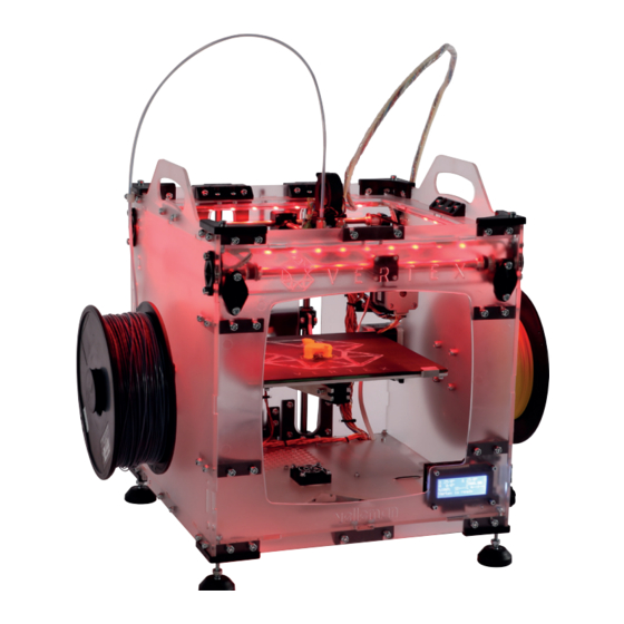
Summary of Contents for Velleman K8400
- Page 1 K8403 USER MANUAL RGB LED ADD-ON FOR K8400 - VERTEX 3D PRINTER W W W . V E L L E M A N P R O J E C T S . E U...
- Page 2 Table of contents What’s in the box What’s on the PCB PCB assembly Attaching the LED strips Installing the firmware Using the LEDs G-code control LED’s get started!
- Page 3 What’s in the box 4x LED strip 20 cm 8x clips 8x double-sided tapes 3x short cables (2 connectors) 1x long white cable (1 connector) 1x long coloured cable (no connector) 4x shrink tubes fig. 1 What’s on the PCB 3x 330 Ω...
- Page 4 PCB assembly Solder the resistors: R1, R2, R3: 330 Ω Orange, Orange, Brown fig. 3 Solder the zener diodes: ZD1, ZD2, ZD3: 2V7 - 1.3 W Mind the polarity marks! fig.4 Solder the logic level FETs: T1, T2, T3: BUK9535-55 fig.
- Page 5 SK1: 2x 6P female headers (14.5 mm pins) fig. 7 Do not cut! fig. 8 Solder the CN2 on the motherboard: 2x 6P female headers (5 mm pins) fig. 9 Mount your assembled PCB on top of the motherboard by plugging the 14.5 mm pins of the K8403 PCB into the two 6P female headers (5 mm pins) on the motherboard.
- Page 6 Attach the LED strips Add 2 clips onto each LED strip at about two centimeters from each end, as shown in picture. fig. 11 Add a piece of double sided tape to each clip. (for your convenience, do not remove the upper layer of the tape yet) fig.
- Page 7 Solder the white cables to the coloured cable as shown in the picture. Mind which cable is soldered to the other! - green wire to white wire with full black line - red wire to white wire with Xs - blue wire to white wire with dotted line - black wire to white wire with symbols fig.
- Page 8 fig. 18 Attach the strips underneath the top of the 3D printer as shown in the pictures. fig. 19 USER MANUAL K8403...
- Page 9 fig. 20 Route the long cable down to the motherboard. Connect the leads in the terminals. fig. 21 Mind the polarity marks! fig. 22 USER MANUAL K8403...
- Page 10 Installing the firmware Download the firmware you need here: www.vertex3dprinter.eu And follow instructions in following link: http://manuals.velleman.eu/article.php?id=31#CHANGINGUPLOADINGTHEFIRMWARE Using the LEDs To control the LEDs go to the ‘menu’, ‘control printer’ and then ‘set LED color’. fig. 23 fig. 24 fig. 25...
- Page 11 Control the LEDs with a G-Code With the M420 code you can control your LED add-on trough G-Code. 1) standard code: M420 Rx Ex Bx 2) x can be 0 or 1 to turn a color on or off 3) R = Red, E = Green, B = Blue Not all values are needed, if a value is missing the previous state of the missing color is kept.
- Page 12 Example sending code with Repetier: USER MANUAL K8403...
- Page 13 /Velleman-nv @Velleman_RnD ORDERCODE: K8403 REVISION: HK8403’1 Velleman nv, Legen Heirweg 33 - Gavere (Belgium) Vellemanprojects.com...


Need help?
Do you have a question about the K8400 and is the answer not in the manual?
Questions and answers