Table of Contents
Advertisement
Installation Guide
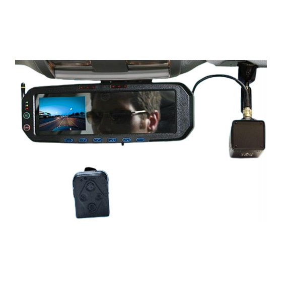
DVM-500Plus
Digital In-Car Video System
Copyright © 2009-2013, Digital Ally, Inc. All Rights Reserved, Printed in U.S.A. This publication may not be reproduced,
stored in a retrieval system, or transmitted in whole or part in any form or by any means electronic, mechanical,
recording, photocopying, or in any other manner without the prior written approval of Digital Ally, Inc.
DVM-500Plus Installation Guide 002-0501-02 REV C
Page 1
Advertisement
Table of Contents

Related Manuals for Digital-Ally DVM-500Plus


Summary of Contents for Digital-Ally DVM-500Plus
-
Page 1: Installation Guide
Digital Ally, Inc. DVM-500Plus Installation Guide 002-0501-02 REV C Page 1... -
Page 2: Table Of Contents
Wiring Connections Chart ............................16 STEP 8: Mount the Interface Box ........................... 17 STEP 9: Wireless Microphone Charging Cradle ......................17 IMPORTANT NOTES WHEN INSTALLING AND USING YOUR DVM-500PLUS ..........17 POST INSTALLATION CHECKLIST .......................... 18 HOW TO RESET THE DVM-500PLUS SYSTEM ....................... 18 TROUBLESHOOTING .............................. -
Page 3: Standard Limited Warranty Model Dvm-500Plus
REAR VIEW MIRROR IN-VEHICLE DIGITAL VIDEO SYSTEM We warranty that our In-Car Digital Video System, Model DVM-500Plus, will be free from defects in workmanship and material for a period of 24 months from the date of purchase by the original purchaser. If... -
Page 4: Before You Begin Installation
Interface (I/O) Box VoiceVault™ 004-09060-00 Wireless Mic (RMT) (Includes 050-0130 Belt Clip) Desktop Charging Cradle 004-0506-00 with AC Power Adapter In Car Charging Cradle 004-0507-00 with DC Auto Adapter Clip-on Style 004-0902-00 Lapel Mic DVM-500Plus Installation Guide 002-0501-02 REV C Page 4... - Page 5 Auxiliary Rear Seat Camera (optional) Sales Call 002-05030-00 Kit, Drop Mount (optional) Sales Big Ball Mirror Mount with Adapter Call 002-05023-00 Plate (optional) Sales Windshield Mount Adapter Kit Call 002-05112-00 (Optional, Dodge Sales Charger only) DVM-500Plus Installation Guide 002-0501-02 REV C Page 5...
-
Page 6: Cautions & Notes
30-90 minutes. If the Backup Battery does not have a high enough charge at the time of installation, the DVM-500Plus system may not turn on correctly the first time. It may be necessary to charge the Backup Battery. -
Page 7: System Diagram
BLACK = Ground DVM to I/O Box harness (See WTM-555 Wireless Transfer installation guide) Module (optional) WTM to DVM serial cable Voice Vault Wireless Microphone and Charger Assembly with Cigarette Lighter Adapter DVM-500Plus Installation Guide 002-0501-02 REV C Page 7... -
Page 8: System Installation
3. Gently apply a small amount of additional inward force toward the glass and rotate the base clockwise. 4. The spring loaded factory mount should release from the windshield puck. See picture Below. Step 2: Remove Factory Body Trim 1. Remove front passenger side threshold DVM-500Plus Installation Guide 002-0501-02 REV C Page 8... - Page 9 2. Pull the door seal away and remove any side trim pieces 3. Remove the passenger side front interior A-pillar cover 4. Remove the passenger visor clip with #20 Torx screwdriver or Phillips screwdriver DVM-500Plus Installation Guide 002-0501-02 REV C Page 9...
-
Page 10: Step 3: Attach The Mirror Mount
However, to safeguard against this possibility we have enclosed the optional adapter plate with stainless steel lanyard and two mounting rings for permanent attachment to your vehicle. DVM-500Plus Installation Guide 002-0501-02 REV C Page 10... -
Page 11: Mounting The Mirror
#6-32 x 1/4" long pan head screw as shown below. Leave the aluminum spacer in place between the DVM and the adapter plate. Apply removable thread locker to both. DVM-500Plus Installation Guide 002-0501-02 REV C Page 11... - Page 12 DVM, i.e. the socket nearest the DVM should move before the socket nearest the windshield moves. Also keep in mind that if you are making this adjustment when the ambient temperature is high, the mount will become tighter as the temperature decreases. DVM-500Plus Installation Guide 002-0501-02 REV C Page 12...
-
Page 13: Step 4: Mirror Connections
Secure your DVM to the vehicle windshield. For 2011 or 2012 Dodge, attach and orientate the adapter to factory windshield as shown below. Use Loctite™ to secure the adapter to the factory windshield mount. Attach optional drop down bracket as shown. DVM-500Plus Installation Guide 002-0501-02 REV C Page 13... -
Page 14: Step 5: Camera Installation
In some vehicles, the factory position of the manufacturer’s windshield mounting plate may not allow for proper rearview DVM adjustment. The mounting plate included with the DVM-500PLUS package can be glued to the windshield in a location that will allow proper adjustment. We recommend Loctite 03346 for installation of the mounting plate. -
Page 15: Step 6: Gps And Rear Microphone Connections
ONLY for the DVM system and not be tapped into for installation of any other equipment in the vehicle. Doing so, could result in possible radio frequency interference from the other equipment. NEVER connect Digital Ally equipment through a vehicle charge guard or battery saver. DVM-500Plus Installation Guide 002-0501-02 REV C Page 15... -
Page 16: Wiring Connections Chart
Left Turn Signal when turn signal is activated Right turn signal input. +12V signal Right Turn Signal when turn signal is activated Reverse input. Signal grounded Reverse when vehicle goes into reverse DVM-500Plus Installation Guide 002-0501-02 REV C Page 16... -
Page 17: Step 8: Mount The Interface Box
YOUR DVM INSTALLATION IS COMPLETE. TURN ON THE VEHICLE’S IGNITION, INSERT THE CF CARD INTO THE DVM-500PLUS, AND PRESS THE “MARK” BUTTON ON THE DVM TO POWER ON THE SYSTEM. IF INSTALLING THE OPTIONAL WIRELESS TRANSFER MODULE, CONSULT THE WTM-555 INSTALLATION GUIDE. -
Page 18: Post Installation Checklist
Bad” will appear on the screen and the unit will fail to start up. Although your CF card is ready to use out of the box, it should be activated through your back office software. Consult the DVM-500Plus User Guide, and the VideoManagerII™ or VuVault™ User’s guides for information on activating your CF card. -
Page 19: Troubleshooting
Upload the videos from the CF card “CF Card Missing or Bad” into VideoManager and then Erase/Format the card. If this fails, then the card may need to be replaced. Contact Product Support for more assistance. DVM-500Plus Installation Guide 002-0501-02 REV C Page 19... -
Page 20: Product Repair
There are no user serviceable parts inside of the DVM, Camera(s), I/O Box, or Remote charging equipment. Remote batteries are user serviceable and can be purchased directly through Digital Ally. 9705 Loiret Blvd Lenexa, KS 66219 Ph: 800-440-4947 or 913-814-7774 Fax: 913-814-7775 Email: support@digitalallyinc.com Website: www.digitalallyinc.com DVM-500Plus Installation Guide 002-0501-02 REV C Page 20... - Page 21 The CE Mark is a European marking of conformity indicating that a product complies with the essential requirements of the applicable European laws or Directives with respect to safety, health, environment, and consumer protection. DVM-500Plus Installation Guide 002-0501-02 REV C Page 21...
Need help?
Do you have a question about the DVM-500Plus and is the answer not in the manual?
Questions and answers