Table of Contents
Advertisement
Advertisement
Table of Contents

Related Manuals for Turnigy TGY-i6S


Summary of Contents for Turnigy TGY-i6S
- Page 1 DIGITAL PROPORTIONAL RADIO CONTROL SYSTEM INSTRUCTION MANUAL...
- Page 2 Thank you for purchasing our product, an ideal radio system for beginners or experienced users alike. Read this manual carefully before operation in order to ensure your safety, and the safety of others or the safe operation of your system. If you encounter any problem during use, refer to this manual first.
-
Page 3: Table Of Contents
6.9 Output Mode......................................6.10 Stick Mode................................6.11 Select Mode................................ 6.12 Model Reset................................ 6.13 Factory Reset............................... 6.14 Firmware Update............................... 6.15 About TGY-i6S..............................7. Product Specifications ........................17 7.1 Transmitter Specifications ..........................17 7.2 Receiver Specifications ............................17 8. Package Contents ..........................18 9. FCC .................................19... -
Page 4: Safety
1. Safety 1.1 Safety Symbols Pay close attention to the following symbols and their meanings. Failure to follow these warnings could cause damage, injury or death. Danger · Not following these instructions may lead to serious injuries or death. Warning ·... -
Page 5: Introduction
2. Introduction The TGY-i6S transmitter and TGY-iA6B receiver constitute a 10 channel 2.4GHz AFHDS 2A digital proportional computerized R/C system. This system supports quadcopters. 2.1 System Features The AFHDS 2A (Automatic Frequency Hopping Digital System Second Generation) is specially developed for all radio control models. -
Page 6: Transmitter Overview
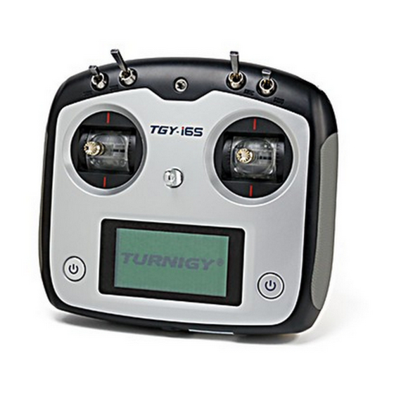
2.2 Transmitter Overview Phone Holder Mounting Point Left Gimbal Right Gimbal Neck Strap Eye Power Button Power Button Capacitive Touch Screen Handle Key 1 Key 2 Battery Cover PS/2 Port USB Port... -
Page 7: Transmitter Antenna
2.2.1 Transmitter Antenna Precautions: • For best signal quality, make sure that the antenna is at about a 90 degree angle to the model. Do not point the antenna directly at the receiver. • Never grip the transmitter antenna during operation. It significantly degrades the RF signal quality and strength and may cause loss of control. -
Page 8: Usb Simulator Mode
2.4 USB Simulator Mode The system may be used as a HID controller when connected to a computer via USB. When connected to a computer the function is activated automatically and will be recognized by windows as a game controller. To calibrate or test the system in windows: •... -
Page 9: Getting Started
3. Getting Started Before operation, install the battery and connect the system as instructed below. 3.1 Transmitter Battery Installation Danger · Only use specified battery. Danger · Do not open, disassemble, or attempt to repair the battery. Danger · Do not crush/puncture the battery, or short the external contacts. Danger ·... -
Page 10: Operation Instructions
4. Operation Instructions After setting up, follow the instructions below to operate the system. 4.1 Power On Follow the steps below to turn on the system: Check the system and make sure that: • The batteries are fully charged and installed properly. •... -
Page 11: Home Screen
5. Home Screen The home screen displays useful information about your model, including timers and TX/RX status. Start Page TX/RX Battery Status + Battery Setup Menu Timers + Timer Menu Main Menu Display Servos Press and hold the screen to perform a servo test. -
Page 12: Timers
5.1 Timers To enter the timer function touch T1/T2 on the main screen. The system has 2 timers available, both can be assigned to a switch and have 3 different settings. Setup: Select a mode. Modes: • Up: The up timer starts from zero and counts up. •... -
Page 13: Function Settings
6. Function Settings 6.1 Reverse The reverse function changes a channels direction of movement in relation to its input. For example, if the blades are spinning in the wrong direction, pushing the model into the ground instead of taking off, this function can be used to correct this. Setup: To change between normal and reverse touch the box to the right side of the desired channel. -
Page 14: Subtrim
6.4 Subtrim Subtrim changes the center point of the channel. For example, if a model is always drifting to one side, the subtrim can be used to fix this. To set the subtrim function: To change the subtrim: Touch the box to the right of the desired channel. Select the correct decimal and use the up and down arrow keys. -
Page 15: Failsafe
• Neg: Changes how much the slave will move in relation to the master in a negative movement. At 50% when the master moves to 100% of its negative motion, the slave will move to negative 50%. Setup: If the mix is not already disabled turn it off by touching the box labeled "on". Select a master by touching the box to the right of the master channel and choose a channel from the list. -
Page 16: Bri./Sound
6.8 Bri./Sound This function controls screen brightness and volume for the system. To make changes to brightness or volume touch and drag the black box located within the relevant slider. Then select icon to save and return to the previous menu. 6.9 Output Mode The system has four output modes, PWM 、... -
Page 17: Select Mode
Once the system has been recognized by the computer select the update button at the bottom of the firmware update software. Once the system has been updated it will restart. Once the system has restarted it is safe to remove the USB cable. 6.15 About TGY-i6S This menu shows the product name, firmware version, firmware release date. -
Page 18: Product Specifications
7. Product Specification 7.1 Transmitter Specification (TGY-i6S) Channels Model type Quadcopter RF range 2.408 ~ 2.475 GHz Bandwidth 500 KHz RF channel RF power Less than 20 dBm 2.4GHz system AFHDS 2A Modulation type GFSK Stick resolution 4096 Low voltage alarm Yes (lower than 4.2V) -
Page 19: Package Contents
8. Package Contents Product Quantity TGY-i6S TGY-iA6B TGY-iA6C Micro USB Cable Sensors: (Optional) • TGY-CPD01 • TGY-CPD02 • TGY-CTM01 • TGY-CVT01 User Manual... -
Page 20: Fcc
9. Appendix 1 FCC Statement This equipment has been tested and found to comply with the limits for a Class B digital device pursuant to part 15 of the FCC rules. These limits are designed to provide reasonable protection against harmful interference in a residential installation.
Need help?
Do you have a question about the TGY-i6S and is the answer not in the manual?
Questions and answers
Bonjour j ai une télécomande tgy-i6s je veeuxliés avec le receveur f.s. gr3e, me donnez la séquence s.v.p. merci bonne journé.