Table of Contents
Advertisement
Quick Links
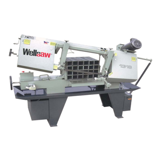
1318
After serial number 5000
Parts List
Manual Bandsaws
and
Built better to work stronger and last longer
Operating & Maintenance Manual
1318
after serial number 5000
REV 170322
2829 N. Burdick St. Kalamazoo, MI 49004
ick St. Kalamazoo, MI 49004
Phone: 269-345-1132 Fax: 269-345-0095
345-1132 Fax: 269-345-0095
www.wellsaw.com
Advertisement
Table of Contents

Related Manuals for Wellsaw 1318


Summary of Contents for Wellsaw 1318
- Page 1 1318 After serial number 5000 Parts List Manual Bandsaws Built better to work stronger and last longer Operating & Maintenance Manual 1318 after serial number 5000 REV 170322 2829 N. Burdick St. Kalamazoo, MI 49004 ick St. Kalamazoo, MI 49004...
-
Page 2: Receiving And Installation
This warranty does not apply if the Wellsaw has been subject to accident, alteration, abuse, misuse or which fails due to lack of care or as the result of inadequate power supply and specifically does not apply to normal wear of moving parts such as bearings, gears, pinion or blade. -
Page 3: Safety Warnings And Instructions
- Always keep machine guards in place. full benefits from your machine. Used properly, - Always put start switch in “OFF” position before Wellsaw’s machinery is among the best in design and plugging in machine. safety. However, any machine used improperly can be When using machine: rendered inefficient and unsafe. -
Page 4: Safety Instructions On Sawing Systems
General Electrical Cautions 19. Some dust created by power sanding, sawing, grinding, This saw should be grounded in accordance with the National drilling and other construction activities contains chemicals Electrical Code and local codes and ordinances. This work known to cause cancer, birth defects or other reproductive should be done by a qualified electrician. -
Page 5: Table Of Contents
Rite-Tension® Blade Tensioning Device Please Contact Factory for Additional Options • Wet Cutting System • Powered Blade Brush Other Models in the 1318 Family • 110 Volts at Controls • Overload and Undervoltage Protection Model 1338 with 38" Width Capacity •... -
Page 6: Notes On Sawing
Notes on Sawing Trouble Shooting It is widely recognized that a proficient operator is a key to optimum bandsawing. He makes certain the Premature Dulling of Blade Teeth machine is properly maintained and adjusted for dependable operation. He carefully sets up each Feed rate too high or low. - Page 7 Premature Blade Breakage necessary. 5. Feed pressure too high. Reduce it. 1. Poor weld in the blade. 6. Blade guides loose, worn or out of alignment. 2. Feed rate set too high. Reduce it. 7. Too many teeth-per-inch. Blade not cutting 3.
-
Page 8: Placing The Blade On Saw
Variable Speed Drive PLACING THE BLADE ON SAW WARNING: When uncoiling a new blade, use Models 1118, 1338, 1348 and 1316S are equipped gloves and eye protection. with variable speed pulleys providing infinite speed To insert a new blade, turn the Adjusting Knob selection between 70 and 375 feet-per-minute. -
Page 9: Hydraulic Feed Control
2. Vertical Adjustment. The back of the saw blade Hydraulic Feed Control should just touch the carbide back up guide (item 15 in the parts drawing) when the saw is running but not cutting. To adjust, loosen the two cap screws 8 The feed rate is hydraulically controlled with a [A] and move the block up or down as required. -
Page 10: Maintenane
4. Military Specification: None. Parts Ordering For your convenience: When contacting your Wellsaw supplier or the Company for parts or service, it is essential that you have your saw Model, Serial Number and Purchase Date available. Jot them down here for handy reference. -
Page 11: Sequence Of Operation
Wellsaw model 1318 Sequence of Operation Pushbutton Feed Control for manually raised saws. 1. At the finish of the cut the blade motor will stop. Be sure to wait until the motor has stopped before removing the cut piece. 2. The saw frame can be lifted to the desired height. There is no need to turn the Cutting Speed handwheel (feed rate control). -
Page 12: Frame Assembly
Frame Assembly... -
Page 13: Frame Assembly
Frame Assembly Frame Assembly Frame A Frame Frame Assembly 1 150146SERV Idle Wheel Guard 2 150147SERV Drive Wheel Guard 55 150060-001 Idle Wheel for 1" Blade 3 100135-002 1/4 Turn Fastener w/cam (includes items 50 - 53) 4 100013-005 Machine Screw, Button Head 10-32 x 3/8 56 B-086 Internal Ring Gear 5 150095... -
Page 14: Bed Assembly
Bed Assembly... - Page 15 Bed Assembly 1 M-065 Locating Pin 2 100004-043 Cap Screw, HH 5/8 x 2-1/2 46 100024-002 Wing Nut, 1/4-20 3 100004-070 Cap Screw, HH 1/2-13 x 1-3/4 47 M-451SERV Stock Stop Arm (fixed) 4 155107 Washer 48 100030-005 Washer, 3/8 5 B-215 Stationary Vise Jaw 49 155205-002...
-
Page 16: Leg & Chip Pan
Leg & Chip Pan Leg & Chip Pan... - Page 17 Leg & Chip Pan 1 F-228 PLASH UARD 2 150077 3 150119 OUNTER ALANCE PRING 4 155016-001 S PRING NCHOR ELDMENT 5 100033-025 S 1/2-13 4” CREW 6 100024-004 W 1/2-13 7 155019-001 S PRING DJUSTER ELDMENT 8 100004-018 C , HH 5/16-18 1 (3 ’...
-
Page 18: Rite Tensioning Device
Rite Tensioning Device® Calibrating the WELLSAW RITE-TENSION ® Blade Tensioning Device The Rite-Tension® device is a simple turn counter that is activated by blade tension and can be easily adjusted in the field. Please review the operation instructions before making any adjustment: 1. - Page 19 Rite Tensioning Device® Caution: The Rite Tension ® blade tensiong device has been factory calibrated for your saw. When re-tightening or replacing a blade, the 'T' handle must be turned counter-clockwise at least six turns to reset the Rite Tension ® mechenism. 150075 Blade Tensioning Ass'y (includes items 2 thru 18)
-
Page 20: Coolant System
Coolant System... -
Page 21: Blade Brush Assembly
Blade Brush Assembly 100165-007 Shoulder bolt, 3/8 x 3/8 15 100165-015 Shoulder bolt 3/8 x 1-3/4 100004-018 Cap screw HH, 5/16-18 x 1 16 100097-001 Washer 100025-002 Lockwasher 5/16 17 150361 Pulley, belt idler 150160-002 Door latch stud 18 100416-001 Bearing 150360 Spring... -
Page 22: Blade Guide Assembly
Blade Guides for 1” Blades Blade Guides for 1” Blades Blade Guides for 1" Blades 35 31... - Page 23 Blade Guides for 1" Blades 152158-001 Blade Guide Ass'y, D.E. (includes items 5 - 31& 35 - 37, minus 7,12,& 28) 152159-001 Blade Guide Ass'y, I. E. (includes items 5 thru 31& 35 - 37 minus 6,11& 29) 152160-001 Guide Support Ass'y, D.E. (includes items 13 - 27 plus 29) 152161-001 Guide Support Ass'y, I.E.
-
Page 24: Hydraulic Cylinder
Hydraulic Cylinder Hydraulic Cylinder Hydraulic Cylinder... -
Page 25: Flow Control Assembly
Flow Control Assembly Flow Control Assembly... -
Page 26: Motor & Gear Box
Motor & Gear Box... - Page 27 Motor & Gear Box 1 100835-037 Motor, 3 HP TEFC, 3/4" shaft, 230/460 3ph 100836-031 Motor, 2 HP, ODP, 115-220/60/1phase 5/8 Shaft 2 100056-037 3 150250 Belt Guard, Bottom Plate 4 105451-021 VS 3 Phase Motor Pulley, 3/4" bore (includes hand wheel 407-712) 105451-005 VS 1Phase Motor Pulley, 5/8"...
-
Page 28: Electrical Controls
Electrical Controls Electrical Controls Electrical Controls... - Page 29 Electrical Controls 155330 Control Switch Assembly (includes 2-10, minus 7) 100871-001 Push Button Start 100871-013 Push Button Stop ** 100871-003 Selector Switch, Coolant ** 100871-019 Push Button 150230-001 Legend Plate 100000-041 Machine Screw, RH 10-32 x 1/2 150236-001 Switch Box Cover 100871-005 Switch Block, Normally Closed 100871-004...
-
Page 30: Electrical Schematic
Electrical Schematic Electrical Schematic... -
Page 31: Backlash Adjustment Proceedure
Procedure to check gear backlash on Wellsaw bandsaws. The applies to saw models with spur type ring & pinion final drive. - Find the six bolts that hold the Ring Gear to the Bandwheel. - Using a dial indicator with a magnetic mount, position the indicator so that the point will contact one of the bolt heads. -
Page 32: Speed & Feed Selection
Stock Dimensions 0 - 1" 1" - 3" 3" - 6" 6"+ Tooth Pitch 10/14, 8/12 8/12, 6/10, 5/8 5/8, 4/6, 3/4, 3 Sabre 3/4, 2/3, 2 Sabre, 1 Tooth, 3/4" T.S. Material (Annealed) Blade Cutting Blade Cutting Blade Cutting Blade Cutting Speed... - Page 33 Stock Dimensions 0 - 1" 1" - 3" 3" - 6" 6"+ Tooth Pitch 10/14, 8/12 8/12, 6/10, 5/8 5/8, 4/6, 3/4, 3 Sabre 3/4, 2/3, 2 Sabre, 1 Tooth, 3/4" T.S. Material (Annealed) Blade Cutting Blade Cutting Blade Cutting Blade Cutting Speed...
-
Page 36: Wellsaw® | 2829 N. Burdick Street | Kalamazoo, Mi
The Original..Since 1926 2829 N. Burdick St. Kalamazoo, MI 49004 Phone: 269-345-1132 Fax: 269-345-0095 website: www.wellsaw.com email: parts@wellsaw.com...
Need help?
Do you have a question about the 1318 and is the answer not in the manual?
Questions and answers