Table of Contents
Advertisement
Quick Links
Advertisement
Table of Contents
Troubleshooting

Related Manuals for Powermatic PWBS-14CS


Summary of Contents for Powermatic PWBS-14CS
- Page 1 This .pdf document is bookmarked Operating Instructions and Parts Manual 14” Woodworking Band Saw Model PWBS-14CS Powermatic 427 New Sanford Rd. LaVergne, TN 37086 Part No. M-1791216 Ph.: 800-274-6848 Revision G 10/2016 www.powermatic.com Copyright © 2016 Powermatic...
-
Page 2: Warranty And Service
Warranty and Service Powermatic warrants every product it sells against manufacturers’ defects. If one of our tools needs service or repair, please contact Technical Service by calling 1-800-274-6846, 8AM to 5PM CST, Monday through Friday. Warranty Period The general warranty lasts for the time period specified in the literature included with your product or on the official Powermatic branded website. -
Page 3: Table Of Contents
Table of Contents Warranty and Service ............................ 2 Table of Contents ............................3 Warning ................................. 5 Introduction..............................6 Features and Specifications .......................... 7 Grounding Instructions ..........................8 115 Volt Operation ............................. 8 230 Volt Operation ............................. 8 Extension Cords ............................9 Unpacking .............................. - Page 4 Parts List: Fence and Rail Assembly ....................... 42 Fence and Rail Assembly ........................43 Parts List: Table and Trunnion Assembly....................44 Parts List: Miter Gauge Assembly ......................45 Parts List: Blade Tension Lever ......................46 Electrical Connections for PWBS-14CS ..................... 47...
-
Page 5: Warning
5. Do not use this band saw for other than its intended use. If used for other purposes, Powermatic disclaims any real or implied warranty and holds itself harmless from any injury that may result from that use. -
Page 6: Introduction
Introduction This manual is provided by Powermatic covering the safe operation and maintenance procedures for a Powermatic Model PWBS-14CS Band Saw. This manual contains instructions on installation, safety precautions, general operating procedures, maintenance instructions and parts breakdown. This machine has been designed and constructed to provide consistent, long-term operation if used in accordance with instructions set forth in this manual. -
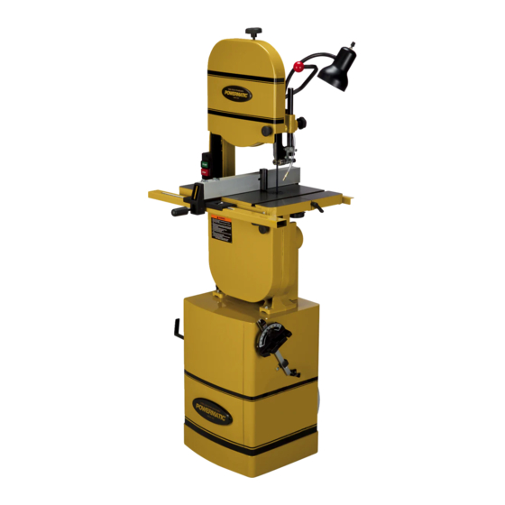
Page 7: Features And Specifications
Features and Specifications Figure 1 Model Number ..........................PWBS-14CS Stock Number ..........................1791216K Resaw (Height) Capacity (in.) ........................6 Cutting Width (Throat Capacity)(in.) ..................... 13-1/2 Minimum Saw Blade Width (in.) ......................... 1/8 Maximum Saw Blade Width (in.) ........................ 3/4 Blade Length (in.) ..........................93-1/2 Main Table Size (LxW)(in.) ........................ -
Page 8: Grounding Instructions
Repair or replace a damaged or worn cord immediately. It is recommended that the PWBS-14CS Band Saw, when operated at 115 volts, be connected to a grounded and dedicated 30 amp circuit with circuit breaker or time delay fuse. When operated at 230 volts, connect the saw to a 20 amp dedicated circuit with breaker or time delay fuse. -
Page 9: Extension Cords
The 115V attachment plug (shown in Figure 6) supplied with the band saw, must be replaced with a UL/CSA listed plug suitable for 230V operation (shown in Figure 7). Contact your local authorized Walter Meier (Manufacturing) Inc., service center or qualified electrician for proper procedures to install the plug. The band saw must comply with all local and national codes after the 230 volt plug is installed. -
Page 10: Unpacking
Unpacking The band saw is shipped in two cartons. Open both cartons and inspect contents for shipping damage. Report any damage immediately to your distributor and shipping agent. Do not discard any shipping material until the Band Saw is assembled and running properly. Compare the contents of both cartons and all internal boxes with the following parts list to make sure all parts are intact.(*) Missing parts, if... - Page 11 (stock no. PWBS14-HP2) Carton #2 - Stand: Refer to Figure 12. Stand with motor (N) pulley cover (O) hardware packages, as follows. Hardware package #3 contains: Refer to Figure 13. Figure 12 2 fence hooks (HP3-A) Stand carton 2 miter gauge hooks (HP3-B) 1 blade hook (HP3-C) 2 pulley cover knobs (HP3-D) 4 carriage bolts, M8x16 (HP3-E)
-
Page 12: Installation And Assembly
Band Saw out of the shipping container and place on top of the stand. Make sure that front of saw (with Powermatic nameplate) faces same direction as curved stand front. 4. Line up holes in the saw base with holes in the top of the stand. -
Page 13: Installing Drive Belt
5. Push motor cord and strain relief plate through the opening to the outside of the stand, as shown in Figure 16. Fasten the strain relief plate to the stand with two M5x12 pan head screws (HP3-G). 6. Connect the plugs of the switch cord and motor cord (Figure 16). -
Page 14: Installing Trunnion Support
Installing Trunnion Support Refer to Figure 21. 1. Use the two locating pins attached to the saw body to help position the trunnion support. Attach trunnion support to saw body with two M8x30 hex cap screws (HP1- J) and two M8 lock washers (HP1-F). Tighten with a 1/2”... -
Page 15: Leveling The Extension Table
Leveling the Extension Table NOTE: Before leveling the extension table, the 90-degree stop of the main table should be verified. Read “Adjusting 90° Table Stop” on page 20, then return to this page. Refer to Figures 22 and 24. 1. Position the main table at 90-degrees and tighten the table locking knobs. -
Page 16: Installing Front Rail And Rip Fence
4. Shift either end of the fence as needed to gain identical distance from table top. 5. Tighten both screws in the rear rail using a 10mm wrench. Installing Front Rail and Rip Fence Refer to Figures 26 through 29. 1. - Page 17 Aligning Fence to Blade Refer to Figure 31. 1. Place the table at 90-degrees. (Make sure the 90° Table Stop setting has been verified – see page 20.) 2. Lock the fence to the guide rail with the handle. 3. Place a square on the table and against the fence, as shown in Figure 31.
-
Page 18: Resaw Guide
Resaw Guide Refer to Figure 32. For resawing operations, attach the resaw guide (HP4-A) to the fence using the knob (HP4-B) through the slotted hole. Position the resaw guide so that it is centered approximately with the front edge of the saw blade. The resaw guide offers a taller, single-point contact surface that allows pivoting of the workpiece in order to keep the blade on the... -
Page 19: Installing Quick Tension Lever
Installing Quick Tension Lever Refer to Figure 36. Install the quick tension lever (M) onto the shaft as shown, and tighten the two set screws using a 3mm hex wrench. The movement of the blade tension lever is explained under “Installing Blades”. -
Page 20: Adjustments
Adjustments Tilting the Table Unplug the machine from the power source before making any repair or adjustment. Refer to Figure 39. 1. Loosen the table locking knobs. 2. Tilt table up to 45 degrees to the right. The angle is indicated on the trunnion scale. Figure 39 3. -
Page 21: Installing Blades
Unplug the machine from the power source before removing or installing blades. The PWBS-14CS Band Saw is provided with a 3/8” wide x 0.020 thick x 93.5” long, 6TPI blade. Refer to Figure 42. The blade tension lever is a patented Carter®... -
Page 22: Blade Tension
6. Remove the current blade from the upper wheel, then the lower wheel. Turn blade to direct it through the slot in the table. blades are usually packaged in coiled position. Use gloves and grasp the coil with one hand while slowly uncoiling the blade with the other hand. -
Page 23: Blade Tracking
Blade Tracking Disconnect machine from power source. Do not adjust blade tracking with the machine running. “Tracking” refers to how the blade is positioned on the wheels while in motion. The blade should track approximately in the center of both wheels, as shown in Figure 44. -
Page 24: Upper Bearing Guides
2. Loosen lock knob and raise or lower upper blade guide assembly to approximately 3/16” above the material being cut. 3. Tighten lock knob. 4. The guide post (Figure 46) is spring loaded. To adjust the tension on the spring, unscrew and completely remove knob, then tighten or loosen set screw, until desired tension is reached. -
Page 25: Miter Gauge
2. Blade must already be tensioned and tracking properly. 3. Loosen thumb screw (J) and move guide block by turning knob (K) so that the front of the guide wheels (L) are just behind the gullet (curved area at base of tooth) of the blade. -
Page 26: On/Off Switch
On/Off Switch The band saw is equipped with a push-button switch that will accept a safety padlock (not included). To safeguard your machine from unauthorized operation and accidental starting by young children, the use of a padlock is highly recommended – see Figure 54. Maintenance Before doing maintenance, disconnect machine from electrical supply... -
Page 27: Blade Selection
A fine pitch (more teeth per inch) will cut slowly Blade Selection but more smoothly. A coarse pitch (fewer teeth per inch) will cut faster but more roughly. Using the proper blade for the job will increase As a rule of thumb, the thicker the workpiece, the operating efficiency of your band saw, help the coarser will be the blade pitch. -
Page 28: Set
Blade Breakage The term “set” refers to the way in which the saw Band saw blades are subject to high stresses teeth are bent or positioned. Bending the teeth and breakage may sometimes be unavoidable. creates a kerf that is wider than the back of the However, many factors can be controlled to help blade. -
Page 29: Operation
Ripping Operation Ripping cutting lengthwise down workpiece, and with the grain (of wood stock). The following section contains basic information, See Figure 58. Always use a push stick or and is not intended to cover all possible similar safety device when ripping narrow applications or techniques using the Band Saw. -
Page 30: Resawing
Resawing It is more common with small, narrow blades, and is almost always attributable to poor blade Resawing is the process of slicing stock to quality, or lack of proper adjustments. Inspect reduce its thickness, or to produce boards that the band saw for the following: are thinner than the original workpiece, such as •... -
Page 31: Troubleshooting - Mechanical And Electrical Problems
Troubleshooting – Mechanical and Electrical Problems Trouble Probable Cause Remedy Machine will not Verify machine is connected to power No incoming power. start/restart or source. repeatedly trips Electrical cord damaged. Replace cord. circuit breaker or blows fuses. Verify that band saw is on a circuit of Building circuit breaker trips or fuse correct size. -
Page 32: Troubleshooting - Operating Problems
Troubleshooting – Operating Problems Trouble Probable Cause Remedy Table tilt does not hold position under Table locking knobs are not tight. Tighten locking knobs . load. Table will not tilt. Trunnion is not lubricated. Grease the trunnion. Disassemble and replace jammed Trunnion is jammed. - Page 33 Trouble Probable Cause Remedy Fence not aligned with blade. Check and adjust fence (see page 17) Wood is warped. Select different wood. Excessive feed rate Reduce feed rate. “Blade lead” occurs (blade wanders Incorrect blade being used for the Change blade to correct type. during cut) particular cut being made.
-
Page 34: Optional Accessories
Trouble Probable Cause Remedy Replace blade, or have blade Blade cooled too rapidly after welding. annealed, or eliminate brittle part and weld correctly. Thrust bearing not properly Check all guide bearings for correct supporting blade, or guide post/side position and signs of wear. Adjust or bearings set too high allowing flex. -
Page 35: Blade Selection Guide
Blade Selection Guide Identify the material and thickness of your workpiece. The chart will show the recommended PITCH, blade TYPE, and FEED RATE. Key: H – Hook L – Low S – Skip M – Medium R – Regular H – High Example: 10/H/M means 10 teeth per inch / Hook Type Blade / Medium Feed For Radius Cutting Study the part drawing or prototype, or actually... -
Page 36: Replacement Parts
To order parts or reach our service department, call 1-800-274-6848, Monday through Friday (see our website for business hours, www.powermatic.com). Having the Model Number and Serial Number of your machine available when you call will allow us to serve you quickly and accurately. - Page 37 Index No. Part No. Description Size 70 ....PWBS14-170 .... Lower Blade Guard ..................1 71 ....TS-1550041 ....Flat Washer ............. M6 ......... 2 72 ....TS-1482041 ....Hex Cap Screw ............M6 x 20 ......2 73 ....PWBS14-173 .... Upper Frame Arm ..................1 74 ....
- Page 38 152 .... PWBS14-252 .... Spacer ......................2 153 .... PWBS14-253 .... Gasket ......................1 154 .... PWBS14-254SN ..Powermatic Nameplate, Small............... 1 155 .... TS-1550041 ....Flat Washer ............. M6 ......... 2 156 .... TS-2361061 ....Lock Washer ............M6 ......... 2 157 ....
-
Page 39: Body Assembly
Body Assembly... -
Page 40: Parts List: Closed Stand Assembly
31 ....TS-1550061 ....Flat Washer ............. M8 ......... 8 32 ....TS-1551061 ....Lock Washer ............M8 ......... 4 33 ....PM2000-105 ....Powermatic Nameplate, Large ..............1 34 ....TS-1550041 ....Flat Washer ............. M6 ......... 2 35 .... -
Page 41: Closed Stand Assembly
Closed Stand Assembly... -
Page 42: Parts List: Fence And Rail Assembly
11 ..F001755 ......Lock Nut (Black) ........M10 .......... 1 12 ..198140 ......Fence Body ....................1 13 ..PWBS14-F01 ....Powermatic Label ........1-3/16 x 2-1/4” ......1 14 ..F011270 ......Pan Hd Phillips Tap Screw (Black) ..#6-20x1/2” ........ 2 15 .. -
Page 43: Fence And Rail Assembly
Fence and Rail Assembly... -
Page 44: Parts List: Table And Trunnion Assembly
Parts List: Table and Trunnion Assembly Index No. Part No. Description Size 41 ....PWBS14-141 .... Table ......................1 42 ....PWBS14-142 .... Table Insert ....................1 43 ....PWBS14-143 .... Table Pin......................1 44 ....PWBS14-144 .... Trunnion......................2 45 .... -
Page 45: Parts List: Miter Gauge Assembly
Parts List: Miter Gauge Assembly Index No. Part No. Description Size ....PWBS14-251 .... Miter Gauge Assembly (Items 1 thru 9) ............1 1 ....PWBS14-251-1 ..Guide Bar....................... 1 2 ....PWBS14-251-2 ..Guide Piece ....................1 3 .... -
Page 46: Parts List: Blade Tension Lever
Parts List: Blade Tension Lever Index No. Part No. Description Size 93 ....PWBS14-193A ..Adjusting Block Assembly (Index # 93-1 thru 93-13) ........1 93-1 ... PWBS14-193-1 ..Side Cover ..................... 1 93-2 ... PWBS14-193-2 ..Spring Pin ...................... 1 93-3 ... -
Page 47: Electrical Connections For Pwbs-14Cs
Electrical Connections for PWBS-14CS... - Page 48 427 New Sanford Rd. LaVergne, TN 37086 Phone: 800-274-6848 www.powermatic.com...
Need help?
Do you have a question about the PWBS-14CS and is the answer not in the manual?
Questions and answers