Datalogic Matrix 120 Reference Manual
Hide thumbs
Also See for Matrix 120:
- Product reference manual (188 pages) ,
- Product reference manual (188 pages)
Table of Contents
Advertisement
Quick Links
Advertisement
Table of Contents
Troubleshooting

Related Manuals for Datalogic Matrix 120


Summary of Contents for Datalogic Matrix 120
- Page 1 > Matrix 120™...
- Page 2 Matrix 120™ Reference Manual Ed.: 11/2016 © 2016 Datalogic S.p.A. and its Group companies ALL RIGHTS RESERVED. Protected to the fullest extent under U.S. and international laws. Copying or altering of this document is prohibited without express written consent from Datalogic S.p.A.
-
Page 3: Table Of Contents
2.6.2 Deformed or Overprinted Code Reading ..............35 2.6.3 Ink-Jet Printing Technology ..................36 2.6.4 Laser Marking/Etching Technology ................36 INSTALLATION ......................37 Package Contents ...................... 37 Mechanical Dimensions ....................38 Mounting and Positioning Matrix 120 ................43 Focus Lock Label (Optional) ..................46... - Page 4 6.2.1 Matrix 120 210-xxx WVGA Models ................67 6.2.2 Matrix 120 310-xxx MP Models .................. 69 Reading Diagrams ...................... 71 6.3.1 Matrix 120 210-xxx 1D Codes (WVGA) ..............72 6.3.2 Matrix 120 210-xxx 2D Codes WVGA ................ 76 6.3.3 Matrix 120 310-xxx 1D Codes (MP) ................80 6.3.4 Matrix 120 310-xxx 2D Codes (MP) ................
- Page 5 Windows XP SP3 and Matrix 120 USB Interface ............. 116 Troubleshooting Guide ..................... 117 TECHNICAL FEATURES ..................120 ALTERNATIVE CONNECTIONS ................122 Power, COM and I/O Connector ................122 On-Board Ethernet Connector .................. 123 Inputs ........................123 Outputs ........................124 CAB-1011 Cable For Opto-Isolated I/O Connections ..........
-
Page 6: References
Reading Methods, provided as supplementary documentation on the DL.CODE mini-DVD (downloaded .zip file or mini-DVD accessory). SUPPORT THROUGH THE WEBSITE Datalogic provides several services as well as technical support through its website. Log on to www.datalogic.com and click on the Industrial Automation links for further information: ... -
Page 7: Compliance
European directive. Since the directives and applicable standards are subject to continuous updates, and since Datalogic promptly adopts these updates, therefore the EU declaration of conformity is a living document. The EU declaration of conformity is available for competent authorities and customers through Datalogic commercial reference contacts. -
Page 8: Eac Compliance
Eurasian mark of conformity. LASER SAFETY All Matrix 120 readers contain one aiming Laser source used to position the reader. This product conforms to the applicable requirements of IEC 60825-1 and complies with 21 CFR 1040.10 except for deviations pursuant to Laser Notice N° 50, date June 24, 2007. This product is classified as a Class 1M laser product according to IEC 60825-1 regulations. -
Page 9: Handling
HANDLING The Matrix 120 is designed to be used in an industrial environment and is built to withstand vibration and shock when correctly installed, however it is also a precision product and therefore before and during installation it must be handled correctly to avoid damage. - Page 10 do not fine tune the positioning by striking the reader or bracket. do not weld the reader into position which can cause electrostatic, heat or reading window damage. do not spray paint near the reader which can cause reading window damage.
-
Page 11: General View
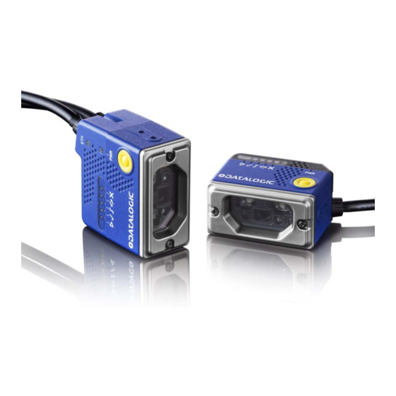
GENERAL VIEW Matrix 120™ Serial + Ethernet Models Figure A Power - Serial Interface - I/O Cable w/Connector Internal Illuminator Ethernet Cable w/ Connector Aiming System Laser Source Ethernet Connection LED Lens HMI X-PRESS Interface Power On LED Good Read LED (green) - Page 12 Matrix 120™ Serial + USB Models Figure B Lens Power On LED Good Read LED (green) HMI X-PRESS Interface Power - Serial Interface - I/O Cable w/Connector Bracket Mounting Holes (4) Internal Illuminator Focus Adjustment Screw 5 Aiming System Laser Source...
-
Page 13: Rapid Configuration
To connect the system in a Ethernet point-to-point configuration, you need the hardware indicated in Figure 3. In this layout the data is transmitted to the Host from the Matrix 120 on- board Ethernet interface by using a CAB-ETH-M0x cable. There is no need to use a crossover adapter since Matrix 120 incorporates an autocross function. - Page 14 USB Connections To connect the system in a USB point-to-point configuration, you need the hardware indicated in Figure 2. In this layout the data is transmitted to the Host from the Matrix 120 USB interface by using a CAB-1021 accessory cable.
- Page 15 Serial Connections To connect the system in a Serial point-to-point configuration, you need the hardware indicated in Figure 3. In this layout the data is transmitted to the Host from the Matrix 120 main serial interface. Matrix 120 power and I/O device connections take place through the CBX connection box using the CAB-1011 accessory cable.
- Page 16 CBX100/CBX500 Pinout for Matrix 120 The table below gives the pinout of the CBX100/CBX500 terminal block connectors. Use this pinout only when the Matrix 120 reader is connected to the CBX100/CBX500 by means of the CAB-1011 accessory cable: CBX100/500 Terminal Block Connectors Input Power...
-
Page 17: Step 2 - Mount And Position The Reader
RAPID CONFIGURATION STEP 2 – MOUNT AND POSITION THE READER 1. To mount the Matrix 120, use the mounting brackets to obtain the most suitable position for the reader. A common mounting configuration is shown in the figure below. Skew Pitch Figure 4 –Positioning with Mounting Bracket... -
Page 18: Step 3 - X-Press Configuration
MATRIX 120™ REFERENCE MANUAL STEP 3 – X-PRESS CONFIGURATION The Matrix 120 models are factory focused to the 70 mm Reading Distance (WVGA models) or 80 mm Reading Distance (MP models). If this distance is compatible with your application you can use the X-PRESS Interface to install the reader, if not, use the DL.CODE procedure described in step 6 “Image Setup. - Page 19 Function of about 5 (five) seconds Matrix 120 will exit without saving the parameters to memory, the Setup LED will stop blinking and in this case Matrix 120 emits a long low pitched beep. Learn 3. Enter the Learn function by pressing and holding the X-PRESS push button until the Learn LED is 4.
- Page 20 X-PRESS push button once. After a short delay the procedure is cancelled. NOTE: If you have used this procedure to configure Matrix 120 go to step 6. Reset Reader to Factory Default Environment (Optional) If it ever becomes necessary to reset the reader’s Environment parameters to their factory default values, you can perform this procedure by holding the X-PRESS push button pressed while powering up the reader.
-
Page 21: Step 4 - Installing Dl.code Configuration Program
2. When the installation is complete the DL.CODE entry is created in the Start>Programs bar under “Datalogic” as well as a desktop icon. Double-click the desktop icon to run it. Depending on your Matrix 120 model, you can connect to the DL.CODE configuration... -
Page 22: Step 4A - Ethernet Device Discovery
MATRIX 120™ REFERENCE MANUAL STEP 4A – ETHERNET DEVICE DISCOVERY The following configuration procedure assumes that a laptop computer running DL.CODE is connected to a factory default reader through the Ethernet port. See Step 1 – Connect the System. The User Interface opens and displays a list of all the devices belonging to the Local Area Network. - Page 23 RAPID CONFIGURATION Figure 11 Device Environment Configuration Window 4. Click OK; the device will reappear in the list of Online Devices (in color) meaning it is now part of the LAN and can be configured. The new IP address will also be displayed.
- Page 24 MATRIX 120™ REFERENCE MANUAL 5. Double-click on or drag the device icon into the Selected Device Information Area. Details about the device will be displayed in this area. Figure 12 – DL.CODE Opening Window NOTE: After device discovery, configure your device through DL.CODE as...
-
Page 25: Step 4B - Usb Device Discovery
See par. 9.2 for more information. The following configuration procedure assumes that a laptop computer running DL.CODE is connected to a Matrix 120 factory default reader through the USB port (CAB-1021). See Step 1 – Connect the System. - Page 26 MATRIX 120™ REFERENCE MANUAL 3. Double-click on or drag the device icon into the Selected Device Information Area. Details about the device will be displayed in this area. NOTE: After device discovery, configure your device through DL.CODE as described in Step 5 – Device Configuration.
-
Page 27: Step 4C - Serial Device Discovery
RAPID CONFIGURATION STEP 4C – SERIAL DEVICE DISCOVERY Starting from DL.CODE 1.4.0, serial port communication is supported for device discovery and configuration. This allows dedicated serial communication models to be configured through DL.CODE. NOTE: Although this feature allows all devices to be configured through their Serial Interface, be aware that transmission speeds and some DL.CODE features are limited when using this interface. - Page 28 MATRIX 120™ REFERENCE MANUAL 6. Open the Serial devices tab and double-click on or drag the device icon into the Selected Device Information Area. The device is now connected to the DL.CODE Configuration environment. Configure your device through DL.CODE as described in Step 5 – Device Configuration.
-
Page 29: Step 5 - Device Configuration
RAPID CONFIGURATION STEP 5 – DEVICE CONFIGURATION Image Setup To begin configuration, the reader must be correctly mounted at the correct reading distance for your application so that its Field of View covers the application reading area. 1. From the Task Area select Open Device Configuration. 2. - Page 30 MATRIX 120™ REFERENCE MANUAL 4. Click the Image Setup button and then click the Image Auto Setup button to automatically acquire the best exposure time and gain values. 5. Select the Static or Dynamic Self-Tuning option; Start Autolearn and Apply to the Image...
- Page 31 RAPID CONFIGURATION NOTE: For applications having multiple lighting or code reading conditions, up to 10 different Image Setups can be configured by adding them with the icon.
- Page 32 MATRIX 120™ REFERENCE MANUAL Code Setup 1. Click on the Code Setup button. By default, the Data Matrix ECC 200 symbology is enabled. If this symbology is among those in your application it will be shown in the image display with its code symbology name and a small green box around it indicating it is decoded.
- Page 33 RAPID CONFIGURATION Reading Phase 1. Select your application specific Operating Mode from the icons over the Configuration Parameters tree area: Continuous, One Shot, or Phase Mode. 2. Configure the relative Operating Mode parameters from the Reading Phase parameters panel. Different groups will appear in the panel depending on the selected icons over the Configuration Parameters tree area.
- Page 34 MATRIX 120™ REFERENCE MANUAL Good Read Setup 1. Select your specific data collection type from the icons over the Configuration Parameters tree area: Code Collection, Code Combination, Presentation or Match Code. Not all data collection types are available for all Operating Modes. Incompatible data collection types will be shown in grey and cannot be selected.
- Page 35 RAPID CONFIGURATION To create a logical AND condition from a logical XOR, create a new Expected Code box using the icon. Then drag the desired code icon from one box to the other. Data Formatting 1. Configure your application specific Data Formatting Message(s) from the Configuration Parameters tree area: Message 1, Message 2, etc.
- Page 36 MATRIX 120™ REFERENCE MANUAL Output Setup 1. Configure your application specific Digital Output(s) and Green/Red Spots (if used) from the Configuration Parameters tree area: Output 1, Output 2, etc. NOTE: Save the configuration from temporary memory to permanent memory, overwriting the previously saved configuration.
-
Page 37: Step 6 - Test Mode
RAPID CONFIGURATION STEP 6 – TEST MODE Use a code suitable to your application to test the reading performance of the system. 1. Enter the Test function by pressing and holding the X-PRESS push button until the Test LED is on. 2. -
Page 38: Advanced Reader Configuration
MATRIX 120™ REFERENCE MANUAL ADVANCED READER CONFIGURATION For further details on advanced product configuration, refer to the DL.CODE User’s Guide available in the DL.CODE Help menu. Host Mode Programming The reader can also be partially configured from a host computer using the Host Mode programming procedure. -
Page 39: Introduction
Food and Beverage environment. As part of the full Matrix series, the Matrix 120 leads the market for customer ease of use because of DL.CODE™ configuration software, X-PRESS™ button and intuitive HMI. -
Page 40: Indicators And Keypad Button
DL.CODE software configurator for outstanding ease of setup X-PRESS, Datalogic’s ‘Green Spot’ technology and intuitive HMI for top ease of use 2.2 INDICATORS AND KEYPAD BUTTON Figure 15 - Indicators The following LED indicators are located on the reader:... - Page 41 INTRODUCTION In normal operating mode the colors and meaning of the five LEDs are illustrated in the following table: green LED indicates that the reader is ready to operate (Figure 15, 3) READY green LED confirms successful reading (Figure 15, 4) GOOD yellow LED indicates the status of the reading phase (Figure 15, 5) TRIGGER...
-
Page 42: X-Press Human Machine Interface
MATRIX 120™ REFERENCE MANUAL 2.3 X-PRESS HUMAN MACHINE INTERFACE X-PRESS is the intuitive Human Machine Interface designed to improve ease of installation and maintenance. Status information is clearly presented by means of the five colored LEDs, whereas the single push button gives immediate access to the following relevant functions: Test Mode with bar graph visualization to check static reading performance. - Page 43 Setup LED will stop blinking and Matrix 120 emits 3 high pitched beeps. If the calibration cannot be reached after a timeout of about 5 (five) seconds Matrix 120 will exit without saving the parameters to memory, the Setup LED will stop blinking and in this case...
-
Page 44: Diagnostic Indication
Matrix 120 emits 3 high pitched beeps. If the autolearning cannot be reached after a timeout of about 3 (three) minutes, Matrix 120 will exit without saving the parameters to memory, the Learn LED will stop blinking and in this case Matrix 120 emits a long low pitched beep. -
Page 45: Model Description
INTRODUCTION 2.4 MODEL DESCRIPTION Matrix 120 readers are described by their model number which indicates the characteristics listed in the diagram below. Not all combinations are available. For a complete list of combinations see the Models tab on the Product page of the website. -
Page 46: Accessories
MATRIX 120™ REFERENCE MANUAL 2.5 ACCESSORIES The following accessories can be used with the Matrix 120 reader. Accessory Description Order No. Cables CAB-1011 M120 M12 Main To CBX (1M) 93A050058 CAB-1021 M120 M12 Main To USB (1M) 93A050059 CAB-1051 M120 M12 Main To USB + I/O (1M) -
Page 47: Application Examples
Figure 17 - Unidose Flow-Pack with PDF417 Code Figure 18 - Overprinted Barcode Readable by Matrix 120 also Through the Envelope Window Film Figure 19 - Barcode Printed on Curved Surface Readable by Matrix 120 in spite of Image Optical Distortion... -
Page 48: Ink-Jet Printing Technology
Figure 21 - Data Matrix Code Directly Marked on PCB Surface by Using Laser Etching Technology CAUTION: Matrix 120 readers are not designed to be used in real-time Laser Marking applications (Mark & Read). They must be mounted far away from the... -
Page 49: Installation
INSTALLATION 3 INSTALLATION 3.1 PACKAGE CONTENTS Verify that the Matrix 120 reader and all the parts supplied with the equipment are present and intact when opening the packaging; the list of parts includes: Matrix 120 reader Quick Reference Guide ... -
Page 50: Mechanical Dimensions
MATRIX 120™ REFERENCE MANUAL 3.2 MECHANICAL DIMENSIONS Matrix 120 can be installed to operate in different positions. The four screw holes (M2.5 x 3.5) on the body of the reader are for mechanical fixture (Figure 23). The diagram below gives the overall dimensions of the reader and may be used for its installation. - Page 51 INSTALLATION Optical Axis [in] Figure 24 – Overall Dimensions of Matrix 120 Ethernet Models with ESD Cover...
- Page 52 MATRIX 120™ REFERENCE MANUAL Optical Axis [in] Figure 25 - Overall Dimensions of Matrix 120 USB Models...
- Page 53 INSTALLATION Optical Axis [in] Figure 26 - Overall Dimensions of Matrix 120 USB Models with ESD Cover...
- Page 54 MATRIX 120™ REFERENCE MANUAL Figure 27 - Mounting Bracket Overall Dimensions...
-
Page 55: Mounting And Positioning Matrix 120
INSTALLATION 3.3 MOUNTING AND POSITIONING MATRIX 120 Using the Matrix 120 mounting brackets you can obtain rotation on the various axes of the reader as shown in the following illustrations: Skew Pitch Figure 28 –Bottom Mounting Positions for USB Models... - Page 56 MATRIX 120™ REFERENCE MANUAL Skew Tilt Figure 30 – Side Mounting Positions for USB Models Figure 31 – Side Mounting Positions for Ethernet Models...
- Page 57 The Pitch, Skew and Tilt angles are represented in Figure 32. Follow the suggestions below for the best orientation: Position the reader in order to avoid the direct reflection of the light emitted by the Matrix 120 reader; it is advised to assure at least 10° for the Skew angle.
-
Page 58: Focus Lock Label (Optional)
MATRIX 120™ REFERENCE MANUAL Linear Barcode Reading 2D Code Reading Figure 33 - Tilt Angle Considerations See chp. 6 for FOV vs. Reading Distance considerations. 3.4 FOCUS LOCK LABEL (OPTIONAL) There are five single-use focus lock labels included in the packaging that can be used to protect the focus position from being changed after the application has been completed. -
Page 59: Cbx Electrical Connections
CBX ELECTRICAL CONNECTIONS 4 CBX ELECTRICAL CONNECTIONS All Matrix 120 models can be connected to a CBX connection box through the CAB-1011 accessory cable. This accessory cable terminates in an M12 17-pin connector on the Matrix 120 side and in a 25-pin male D-sub connector on the CBX side. -
Page 60: Power Supply
MATRIX 120™ REFERENCE MANUAL NOTE: To avoid electromagnetic interference when the reader is connected to a CBX connection box, verify the jumper positions in the CBX as indicated in its Installation Manual. 4.1 POWER SUPPLY Power can be supplied to the reader through the CBX100/500 spring clamp terminal pins as... -
Page 61: Rs232 Interface
CBX ELECTRICAL CONNECTIONS 4.2.1 RS232 Interface The RS232 interface is generally used for Point-to-Point connections. When it is connected to the host computer it allows transmission of code data. The following pins are used for RS232 interface connection: CBX100/500 Function Transmit Data Receive Data SGND... -
Page 62: Rs422 Full-Duplex Interface
MATRIX 120™ REFERENCE MANUAL 4.2.2 RS422 Full-Duplex Interface The RS422 full-duplex (5 wires + shield) interface is used for non-polled communication protocols in point-to-point connections over longer distances (max 1200 m / 3940 ft) than those acceptable for RS232 communications or in electrically noisy environments. -
Page 63: Inputs
CBX ELECTRICAL CONNECTIONS 4.4 INPUTS CAUTION: When Inputs 1 and 2 are connected through the CBX connection box, they become opto-isolated and polarity insensitive and acquire the electrical characteristics listed below. To function correctly, they require setting the Input Line Type configuration parameters to NPN for the respective input. - Page 64 Input Device on the +V/-V spring clamps, and does not pass through the Power Switch (ON/OFF) inside the CBX. Disconnect the power supply when working inside the CBX. Photoelectric Sensor Figure 38 – PNP External Trigger Using Matrix 120 Power...
- Page 65 CBX ELECTRICAL CONNECTIONS Photoelectric Sensor Figure 39 - NPN External Trigger Using Matrix 120 Power...
- Page 66 Input 2 B (polarity insensitive) Power Reference - Inputs INPUT 2 CONNECTIONS USING MATRIX 120 POWER CAUTION: Power from the Vdc/GND spring clamps is available directly to the Input Device on the +V/-V spring clamps, and does not pass through the Power Switch (ON/OFF) inside the CBX.
- Page 67 CBX ELECTRICAL CONNECTIONS Input Device Power to Input Input Device Signal Input Device Reference NPN Input 2 Using MATRIX 120 Power INPUT 2 CONNECTIONS USING EXTERNAL POWER Input Device Input Signal Pulled down to External Input Device Reference Figure 42 - PNP Input 2 Using External Power...
-
Page 68: Outputs
MATRIX 120™ REFERENCE MANUAL 4.5 OUTPUTS CAUTION: When Outputs 1 and 2 are connected through the CBX connection box, they become opto-isolated and polarity sensitive and acquire the electrical characteristics listed below. To function correctly, they require setting the Output Line Type configuration parameters to NPN for the respective output. - Page 69 Output device Signal Output device Signal Output device Output device Reference Reference Figure 44 - PNP/Open Emitter Output Using MATRIX 120 Power Output 1 Device Output 2 Device Power to Power to Output device Output device Output device Output device...
-
Page 70: On-Board Ethernet Interface
For Ethernet models, the on-board Ethernet Interface can be used for TCP/IP communication with a remote or local host computer by connecting the reader to either a LAN or directly to a host PC. There is no need to use a crossover adapter since Matrix 120 incorporates an auto- cross function. -
Page 71: Typical Layouts
The Ethernet connection is possible in two different layouts. In a Point-to-Point layout the reader is connected to a local host by using a CAB-ETH-M0x cable. There is no need to use a crossover adapter since Matrix 120 incorporates an autocross function. - Page 72 MATRIX 120™ REFERENCE MANUAL When using a Local Area Network (LAN), one or more Matrix 120 readers can be connected to the network by using CAB-ETH-M0x cables: Matrix 120 10-30 Vdc Power CAB-1011 Host Switch Ethernet Interface Main Serial Interface (Data Monitor) ...
-
Page 73: Serial Connection
When One Shot or Phase Mode operating mode is used, the reader can be activated by an External Trigger (for example a pulse from a photoelectric sensor) when the object enters its reading zone. 10-30 Vdc External Power for Matrix 120 and I/O Accessories Host Matrix 120 ... -
Page 74: Fieldbus Connection
Therefore neither data monitoring nor device configuration can be performed through this interface. Once the Matrix 120 device is configured in DL.CODE for HMS Fieldbus communication the Main Serial channel is no longer available. Therefore it is recommended to make these configurations when connected to DL.CODE through either the Ethernet interface (using CAB-ETH-Mxx) or the... -
Page 75: Pass-Through
TYPICAL LAYOUTS 5.4 PASS-THROUGH The pass-through layout allows each device to collect data from one or more pass-through input channels and send this data plus its own on one or more different output channels. In this way independent devices can be connected together in combinations to create multi device networks. -
Page 76: Usb Connection
NOTE: USB-HID (Keyboard Wedge) configurations can also be made through this interface. See par. 7.4 for more information. One or more Matrix 120 USB models can be connected to a USB Hub. The HUB must be able to supply 500 mA to each port. - Page 77 I/O Accessories Matrix 120 Figure 55 – USB Point-to-Point Layout with I/O The electrical connections between I/O devices and CAB-1051, together with the relative Matrix 120 Line Type parameter settings are shown below. Inputs Outputs = 5-30 Vdc max = 5-30 Vdc max = 3.5 mA max...
-
Page 78: Reading Features
Figure 56 – Reading Distance References Example: The FOV for a Matrix 120 310-xxx at a reading distance of 100 mm is: = 2 [(100 mm + 8 mm) tan (41°/2)] 81 mm = 2 [(100 mm + 8 mm) tan (32°/2)] 62 mm... -
Page 79: Global Fov Diagrams
Processing Mode = Standard. Depending on the code resolution, symbology, and number of characters in the code, the Reading Area can be different from the FOV. See the reference Reading Diagrams starting from par. 6.3.1 for specific reading area examples. 6.2.1 Matrix 120 210-xxx WVGA Models 1D Codes -0.5 -1.0 -1.5... - Page 80 MATRIX 120™ REFERENCE MANUAL 2D Codes -0.5 -1.0 -1.5 -2.0 Distance Figure 58 – Global FOV 2D Code Diagram for WVGA Models...
-
Page 81: Matrix 120 310-Xxx Mp Models
READING FEATURES 6.2.2 Matrix 120 310-xxx MP Models 1D Codes Distance Figure 59 – Global FOV 1D Code Diagram for MP Models... - Page 82 MATRIX 120™ REFERENCE MANUAL 2D Codes -0.5 -1.0 -1.5 -2.0 -2.5 -3.0 Distance Figure 60 – Global FOV 2D Code Diagram for MP Models...
-
Page 83: Reading Diagrams
Data Matrix ECC 200 (2D code) from the Test Charts available in the SW-DOCS-TEST CHART accessory (93ACC0148). Testing should be performed with the actual Matrix 120 using application codes in order to evaluate whether maximizing application performance requires adjustments to the HW/SW configuration with respect to the Reference Conditions given under each diagram. -
Page 84: Matrix 120 210-Xxx 1D Codes (Wvga)
MATRIX 120™ REFERENCE MANUAL 6.3.1 Matrix 120 210-xxx 1D Codes (WVGA) Matrix 120 210 (WVGA) Code 128 0.12 mm (5 mils) -0.5 -1.0 -1.5 Reading Distance CONDITIONS: Hardware Settings Code Symbology Code 128 Code Resolution 0.12 mm (5 mils) Tilt Angle 0°... - Page 85 READING FEATURES Matrix 120 210 (WVGA) Code 128 0.20 mm (8 mils) -0.5 -1.0 -1.5 -2.0 Reading Distance CONDITIONS: Hardware Settings Code Symbology Code 128 Code Resolution 0.20 mm (8 mils) Tilt Angle 0° Skew Angle 15° Focusing Distance (mm) Software Parameters Exposure Time (µs)
- Page 86 MATRIX 120™ REFERENCE MANUAL Matrix 120 210 (WVGA) Code 128 0.25 mm (10 mils) -2.5 -0.5 -1.0 -1.5 -2.0 -2.5 Reading Distance CONDITIONS: Hardware Settings Code Symbology Code 128 Code Resolution 0.25 mm (10 mils) Tilt Angle 0° Skew Angle 15°...
- Page 87 READING FEATURES Matrix 120 210 (WVGA) Code 128 0.33 mm (13 mils) -0.5 -1.0 -1.5 -2.0 -2.5 Reading Distance CONDITIONS: Hardware Settings Code Symbology Code 128 Code Resolution 0.33 mm (13 mils) Tilt Angle 0° Skew Angle 15° Focusing Distance (mm) Software Parameters Exposure Time (µs)
-
Page 88: Matrix 120 210-Xxx 2D Codes Wvga
6.3.2 Matrix 120 210-xxx 2D Codes WVGA Vignetting For Matrix 120 readers used in 2D code reading applications, due to the "fisheye" or “vignetting” effect of the lens, the reading area is limited to the central zone of the Vertical Field of View. - Page 89 READING FEATURES Matrix 120 210 (WVGA) Data Matrix 0.12 mm (5 mils) 1.00 0.75 0.50 0.25 -0.25 -0.50 -0.75 -1.00 Reading Distance CONDITIONS: Hardware Settings Code Symbology Data Matrix ECC 200 Code Resolution 0.12 mm (5 mils) Tilt Angle 0°...
- Page 90 MATRIX 120™ REFERENCE MANUAL Matrix 120 210 (WVGA) Data Matrix 0.19 mm (7.5 mils) -0.5 -1.0 -1.5 Reading Distance CONDITIONS: Hardware Settings Code Symbology Data Matrix ECC 200 Code Resolution 0.19 mm (7.5 mils) Tilt Angle 0° Skew Angle 15°...
- Page 91 READING FEATURES Matrix 120 210 (WVGA) Data Matrix 0.25 mm (10 mils) -0.5 -1.0 -1.5 Reading Distance CONDITIONS: Hardware Settings Code Symbology Data Matrix ECC 200 Code Resolution 0.25 mm (10 mils) Tilt Angle 0° Skew Angle 15° Focusing Distance (mm) Software Parameters Exposure Time (µs)
-
Page 92: Matrix 120 310-Xxx 1D Codes (Mp)
MATRIX 120™ REFERENCE MANUAL 6.3.3 Matrix 120 310-xxx 1D Codes (MP) Matrix 120 310 (MP) Code 128 0.12 mm (5 mils) -0.5 -1.0 -1.5 Reading Distance CONDITIONS: Hardware Settings Code Symbology Code 128 Code Resolution 0.12 mm (5 mils) Tilt Angle 0°... - Page 93 READING FEATURES Matrix 120 310 (MP) Code 128 0.20 mm (8 mils) -0.5 -1.0 -1.5 -2.0 -2.5 Reading Distance CONDITIONS: Hardware Settings Code Symbology Code 128 Code Resolution 0.20 mm (8 mils) Tilt Angle 0° Skew Angle 15° Focusing Distance (mm) Software Parameters Exposure Time (µs)
- Page 94 MATRIX 120™ REFERENCE MANUAL Matrix 120 310 (MP) Code 128 0.25 mm (10 mils) -0.5 -1.0 -1.5 -2.0 -2.5 Reading Distance CONDITIONS: Hardware Settings Code Symbology Code 128 Code Resolution 0.25 mm (10 mils) Tilt Angle 0° Skew Angle 15°...
- Page 95 READING FEATURES Matrix 120 310 (MP) Code 128 0.33 mm (13 mils) Reading Distance CONDITIONS: Hardware Settings Code Symbology Code 128 Code Resolution 0.33 mm (13 mils) Tilt Angle 0° Skew Angle 15° Focusing Distance (mm) Software Parameters Exposure Time (µs)
-
Page 96: Matrix 120 310-Xxx 2D Codes (Mp)
6.3.4 Matrix 120 310-xxx 2D Codes (MP) Vignetting For Matrix 120 readers used in 2D code reading applications, due to the "fisheye" or “vignetting” effect of the lens, the reading area is limited to the central zone of the Vertical Field of View. - Page 97 READING FEATURES Matrix 120 310 (MP) Data Matrix 0.076 mm (3 mils) 1.00 0.75 0.50 0.25 -0.25 -0.50 -0.75 -1.00 1.25 1.50 1.75 2.00 2.25 Reading Distance CONDITIONS: Hardware Settings Code Symbology Data Matrix ECC 200 Code Resolution 0.076 mm (3 mils) Tilt Angle 0°...
- Page 98 MATRIX 120™ REFERENCE MANUAL Matrix 120 310 (MP) Data Matrix 0.13 mm (5 mils) -0.5 -1.0 -1.5 Reading Distance CONDITIONS: Hardware Settings Code Symbology Data Matrix ECC 200 Code Resolution 0.12 mm (5 mils) Tilt Angle 0° Skew Angle 15°...
- Page 99 READING FEATURES Matrix 120 310 (MP) Data Matrix 0.19 mm (7.5 mils) -0.5 -1.0 -1.5 -2.0 Reading Distance CONDITIONS: Hardware Settings Code Symbology Data Matrix ECC 200 Code Resolution 0.19 mm (7.5 mils) Tilt Angle 0° Skew Angle 15° Focusing Distance (mm) Software Parameters Exposure Time (µs)
- Page 100 MATRIX 120™ REFERENCE MANUAL Matrix 120 310 (MP) Data Matrix 0.25 mm (10 mils) -0.5 -1.0 -1.5 -2.0 -2.5 Reading Distance CONDITIONS: Hardware Settings Code Symbology Data Matrix ECC 200 Code Resolution 0.25 mm (10 mils) Tilt Angle 0° Skew Angle 15°...
-
Page 101: Maximum Line Speed And Exposure Time Calculations
(internal lighting system, optical lens, reading distance) and on any external lighting system. It may also depend on code printing quality, and reader position. Example: A Matrix 120 using: Internal Lighting Mode = Very High Power Strobe ... - Page 102 MATRIX 120™ REFERENCE MANUAL Likewise, T is the maximum Exposure Time value that can be used without blurring exp (max) for the given application line speed and code resolution. Therefore: X / LS = T exp (max) and LS are represented in the graph below as the curved line for X (code...
-
Page 103: Software Configuration
SOFTWARE CONFIGURATION 7 SOFTWARE CONFIGURATION Software configuration of your Matrix 120 for static reading or simple code reading applications can be accomplished by the Rapid Configuration procedure using the X-PRESS HMI (which requires no external configuration program). This procedure is described in chapter 1 Steps 3-4. -
Page 104: Auto Calibration
MATRIX 120™ REFERENCE MANUAL 7.2.1 Auto Calibration DL.CODE provides the Image Auto-Setup tool to maximize the reading performance by tuning the acquisition parameters (photometry) automatically. By selecting the Image Auto- Setup tool from the Image Setup step, the following window appears: Figure 63 –... -
Page 105: Manual Calibration
SOFTWARE CONFIGURATION 7.2.2 Manual Calibration The following examples show some of the typical conditions occurring during the installation and how they can be tuned manually: Under-exposure: To correct this result it is recommended to change the following parameters in their order of appearance: 1. - Page 106 MATRIX 120™ REFERENCE MANUAL Over-exposure: To correct this result it is recommended to change the following parameters in their order of appearance: 1. decrease the Gain 2. decrease the Exposure Time Figure 66 - Example Over Exposure: Too Light...
- Page 107 SOFTWARE CONFIGURATION Moving code out of the Field of View: To correct this result and have the code completely visible in FOV, it is possible to follow one or both the procedures listed below: reposition the reader use the Delay on Trigger and set the time value (µs). Figure 67 - Example out of FOV...
-
Page 108: Multi Image Acquisition Settings
MATRIX 120™ REFERENCE MANUAL 7.2.3 Multi Image Acquisition Settings When controlled variable conditions occur in the application, Multiple Image Acquisition Settings can be defined to create a database of parameter groups that handle each specific application condition. This database of pre-defined settings improves system flexibility and readiness by being applied either automatically or selectively by an activation event. - Page 109 SOFTWARE CONFIGURATION Automatic Image Settings Selection If we don’t know from one item to the next which reading condition will be presented, we will cycle through the pre-defined database of Image Settings (one per acquisition) in order to automatically capture the correctly lighted image over the course of several acquisitions. When the correct condition is matched, the result should be able to produce a Good Read.
- Page 110 MATRIX 120™ REFERENCE MANUAL External Image Settings Selection There are some applications where the lighting conditions are known before each item is read and therefore we can pre-select the correct Image Setting from an external source. When the Image Settings Selection is External, Acquisition Sequences are created and by default each Image Setting has its own Acquisition Sequence.
- Page 111 SOFTWARE CONFIGURATION Alternatively a hybrid configuration can be made where more than one Image Setting can be grouped into an Acquisition Sequence by dragging it into the desired Sequence box. Select the empty Sequence box and delete it with the delete key. Each Acquisition Sequence can be activated exclusively by a single event, either through a string from an available communication channel or by a digital input.
-
Page 112: Image Cropping
Add Cropping Region icon as shown below. In Matrix 120 the frame rate is dependent on the number of rows and columns in the defined window. Image cropping allows reducing the Image processing area from the full FoV to a smaller area where codes are present. - Page 113 SOFTWARE CONFIGURATION After clicking the Add Cropping Region icon, a blue border appears which by default is equal to the FoV. By dragging the edges with the mouse (resizing) you can crop the image to a specific location where codes are present. The numbers in the blue boxes refer to pixel references. x,y coordinates of upper left corner of Cropping Region...
- Page 114 MATRIX 120™ REFERENCE MANUAL The cropped area can be moved by dragging the center. You can also set the cropped image size and position through the Cropping Region Area group of parameters; size = Width and Height, position = Left, Top (x,y) coordinates.
-
Page 115: Direct Part Marking Applications
To minimize decoding time it is better to select the lowest value that still guarantees good decoding. Matrix 120 is indicated for DPM applications where the parts are marked by Laser Etching. Various Image Filters are available to enhance Direct Part Marking applications. For more... -
Page 116: Pass-Through Configurations
MATRIX 120™ REFERENCE MANUAL 7.3 PASS-THROUGH CONFIGURATIONS DL.CODE supports pass-through multi device configurations. The pass-through configuration allows individually working devices, to collect data from other devices, and pass this data to a third device through a different communication channel. The following screenshots show the pass-through configuration settings for the three devices in the example in par. -
Page 117: Usb-Hid (Keyboard Wedge) Configurations
In this configuration code reading input from the Matrix 120 is sent directly to the application running on the PC as if it was typed from the PC keyboard. This is typically used in data entry programs. - Page 118 MATRIX 120™ REFERENCE MANUAL The USB-HID interface is a Matrix 120 Output only channel and is configured through the Data Formatting page. You need to correctly set the Header and Terminator parameters depending on the requirements of the application running on the PC.
-
Page 119: Backup And Restore Through Dl.code
DL.CODE provides complete backup and restore functions (Configuration and Environmental parameters) for Matrix 120 readers. Backup and Restore functions provide parameter storage including all configuration jobs present on the reader. CAUTION: It is strongly recommended to save all configurations to backup files. -
Page 120: Backup
MATRIX 120™ REFERENCE MANUAL 7.5.1 Backup To perform a Backup: 1. From the DL.CODE Device menu, select Single Reader Backup (to file on PC). You will be reminded that configuration in temporary memory will not be saved so you should save the configuration to the reader before performing Backup. -
Page 121: Restore
SOFTWARE CONFIGURATION 7.5.2 Restore To perform a Restore: 1. From the DL.CODE Device menu, select Single Reader Restore (from file on PC). At the end of the restore, DL.CODE shows a message indicating successful completion. 7.5.3 Replacement CAUTION: The replacement device must be the exact same model as the device it is replacing. -
Page 122: Restore Defaults
MATRIX 120™ REFERENCE MANUAL 7.6 RESTORE DEFAULTS The device parameters are divided into two main classes, Configuration and Environment which are affected differently by the Restore Defaults commands. The Configuration parameters are the ones set in the various steps of the configuration process and are specific to each application. -
Page 123: Restore Default Environment
Device Environment Configuration window. The Factory Default static IP address for all Matrix 120 Ethernet model readers is: IP Address = 192.168.3.100 Any previously saved configurations on the device will remain in memory, but the Default... -
Page 124: Restore Factory Defaults
MATRIX 120™ REFERENCE MANUAL 7.6.3 Restore Factory Defaults In order to return a device to its absolute Factory default parameters (for example device replacement) it is necessary to use the Restore Factory Defaults command. You will be prompted to confirm. -
Page 125: Statistics
SOFTWARE CONFIGURATION For Matrix 120 readers some of these alarms are not relevant. The following table shows the relevant alarms: Alarm Description Meaning Code Protocol Index Failure The expected Protocol Index is not received Fieldbus Communication There is a communication error between the scanner and... - Page 126 MATRIX 120™ REFERENCE MANUAL The enabled Statistical Counters can be selected from the Device>Settings>Configuration Settings menu.
-
Page 127: Maintenance
MAINTENANCE 8 MAINTENANCE 8.1 CLEANING Clean the lens cover see Figure A, 4 periodically for continued correct operation of the reader. Dust, dirt, etc. on the lens cover may alter the reading performance. Repeat the operation frequently in particularly dirty environments. Use soft material and alcohol to clean the lens cover and avoid any abrasive substances. -
Page 128: Troubleshooting
Connect the device and click on the link to the parameter you’re interested in. If you’re unable to fix the problem and you’re going to contact your local Datalogic office or Datalogic Partner or ARC, we suggest providing (if possible): Application Program version, Parameter Configuration file, Serial Number and Order Number of your reader. -
Page 129: Troubleshooting Guide
TROUBLESHOOTING 9.3 TROUBLESHOOTING GUIDE TROUBLESHOOTING GUIDE Problem Suggestion DL.CODE Installation: Check Windows settings to see if Autorun is disabled. Autorun or Start.hta doesn’t Associate the file type .hta with the Microsoft HTML Application host mshta.exe in Windows\System32. Power ON: Is power connected? the “POWER”... - Page 130 MATRIX 120™ REFERENCE MANUAL TROUBLESHOOTING GUIDE Problem Suggestion Any Operating Mode: Check the Code Collection parameters on the Reading ”TRIGGER” Phase step and the Data Formatting parameters on the correctly blinking but no result Data Formatting step. is transmitted by the reader at the end of the reading phase collection.
- Page 131 The reader Order Number consists of 9 numbers. Order Number? The reader Order Number can be obtained by comparing the Device Model (in DL.CODE Device Menu > Settings > Settings > About Device) with the product models page on the Datalogic website.
-
Page 132: Technical Features
MATRIX 120™ REFERENCE MANUAL 10 TECHNICAL FEATURES ELECTRICAL FEATURES Power Supply Voltage 5 to 30 Vdc (10 to 30 Vdc with CBX) Consumption 0.4 to 0.1 A Communication Interfaces Main - RS232 2400 to 115200 bit/s - RS422 full-duplex 2400 to 115200 bit/s USB 2.0 Hi-Speed... -
Page 133: Software Features
TECHNICAL FEATURES Serial + USB Serial + Ethernet PHYSICAL FEATURES Dimensions Standard Models 45.4 x 31.1 x 23.5 mm 45.4 x 48.5 x 23.5 mm (1.8 x 1.2 x 1 in.) (1.8 x 1.9 x 1 in.) Dimensions ESD Safe 45.4 x 35.4 x 23.5 mm 45.4 x 52.8 x 23.5 mm (1.8 x 1.4 x 1 in.) -
Page 134: Aalternative Connections
The connector pinouts and notes given in this appendix are for custom cabling applications. POWER, COM AND I/O CONNECTOR The Matrix 120 reader is equipped with an M12 17-pin male connector for connection to the power supply, serial interfaces and input/output signals. The details of the connector pins are indicated in the following table: Figure 70 –... -
Page 135: On-Board Ethernet Connector
ALTERNATIVE CONNECTIONS ON-BOARD ETHERNET CONNECTOR A Standard M12 D-Coded female connector is provided for the on-board Ethernet connection. This interface is IEEE 802.3 10 BaseT and IEEE 802.3u 100 BaseTx compliant. Figure 71 - M12 D-Coded Female Ethernet Network Connector On-Board Ethernet Network Connector Pinout Name Function... -
Page 136: Outputs
MATRIX 120™ REFERENCE MANUAL OUTPUTS Two general purpose non opto-isolated but short circuit protected outputs are available on the M12 17-pin connector of the reader. The electrical features of the two outputs are the following: Reverse-Polarity and Short-Circuit Protected = -100 mA) max = 28.3 Vdc (when using 30 Vdc power supply) LOAD = 100 mA) max = 1.7 Vdc... - Page 137 ALTERNATIVE CONNECTIONS Matrix 120™ USER INTERFACE Vext Figure 73 - NPN Output Connection Matrix 120™ USER INTERFACE Figure 74 - Push-Pull Output Connection...
-
Page 138: Cab-1011 Cable For Opto-Isolated I/O Connections
CAB-1051 CABLE FOR USB INTERFACE WITH I/O CONNECTIONS The CAB-1051 accessory cable allows the USB interface to be used with input/output signals between the Matrix 120 reader and the I/O devices. These signals are referenced to GND. CAB-1051 Wires Name... -
Page 139: User Interface - Serial Host
The following wiring diagram shows a simple test cable including power, external (push- button) trigger and PC RS232 COM port connections. M12 17-pin female 9-pin D-sub female 11 RX Matrix 120 Power Supply Power GND VS (10 – 30 VDC) Trigger Figure 76- Test Cable for Matrix 120... -
Page 140: Glossary
GLOSSARY (Association for Automatic Identification and Mobility): AIM Global is the international trade association representing automatic identification and mobility technology solution providers. AIM DPM Quality Guideline Standard applicable to the symbol quality assessment of direct part marking (DPM) performed in using two-dimensional bar code symbols. It defines modifications to the measurement and grading of several symbol quality parameters. - Page 141 Depth of Field The difference between the minimum and the maximum distance of the object in the field of view that appears to be in focus. Diffused Illumination Distributed soft lighting from a wide variety of angles used to eliminate shadows and direct reflection effects from highly reflective surfaces.
- Page 142 (International Organization for Standardization): A network of the national standards institutes of several countries producing world-wide industrial and commercial standards. LED (Light Emitting Diode) A low power electronic light source commonly used as an indicator light. It uses less power than an incandescent light bulb but more than a Liquid Crystal Display (LCD).
-
Page 143: Index
Manual Calibration, 93 Application Examples, 35 Mechanical Dimensions, 38 Auto Calibration, 92 Model Description, 33 Mounting and Positioning Matrix 120, 43 Multi Image Acquisition Settings, 96 Backup and Restore, 107 On-Board Ethernet Interface, 58 Outputs, 56, 124 CBX Electrical Connections, 47...
Need help?
Do you have a question about the Matrix 120 and is the answer not in the manual?
Questions and answers