Table of Contents
Advertisement
Advertisement
Table of Contents

Summary of Contents for Technicolor COM2000
- Page 1 Technicolor COM2000 Integrator’s Manual...
-
Page 2: Table Of Contents
5.8 DIRECTV Activation ........................ 27 Getting Started ........................... 28 6.1 Assembly ........................... 28 6.2 Setting up Multiple Chassis....................... 29 The COM2000 Web Interface ....................31 7.1 The Overview Page ........................32 7.2 Discover Page ..........................36 7.3 Explanation of Discover Page Fields ..................37 7.4 The Tune Command ........................ - Page 3 Using the VidPlay Feature ....................51 Using the COM46 “Simulcrypt” Feature ................51 7.15 7.16 Using the COM46 REST Feature ..................52 7.17 Displaying COM2000 Status ..................... 52 7.18 Pairing Info ........................53 7.19 Tune all Command ......................56 7.20 Refreshing the COM2000 Display..................
- Page 4 15.1 PID Mapping at the COM46 Receiver................104 15.2 Best Practices to Avoid Key Loss ..................105 15.3 EdgeQAM PID remapping ....................106 16 Technicolor ATSC-8 Users Guide ..................109 16.1 Introduction ........................110 16.2 Over-the-Air Broadcasts ....................110 16.3 Advantages of ATSC Broadcast Channels ..............
- Page 5 Table of Figures 1 - COM2000 S ..................12 IGURE YSTEM VERVIEW 2 - COM2000 F ....................16 IGURE RONT 3- COM2000 R ..................... 17 IGURE 4 - COM46 C ......................... 18 IGURE 5 - COM46 F ......................20 IGURE 6 - QAM6 C ........................
- Page 6 43 - COM2000 H ..................60 IGURE EALTH 44 - S ......................62 IGURE YSLOG XAMPLE 45 - COM2000 EPG P ....................65 IGURE 46 - COM2000 EPG P ) ................68 IGURE ONFIGURED 47 - COM46 EPG L ..................69...
- Page 7 64 - A .................. 87 IGURE DVANCED RANSFER 65 - M COM46 SW U ................88 IGURE ULTI PDATE 66 - M .................. 88 IGURE ULTI PGRADE ESULTS 67 - A ............89 IGURE PPLYING A ICENSE ILE TO NABLE EATURES 68 - U QAM6 S...
- Page 8 96 - ATSC L ....................122 IGURE UNCTION 99 - ATSC T ..................... 123 IGURE ABLE 98 - Q ..................124 IGURE UERY OMMAND ESULTS 99 - EPG PSIP P ................... 125 IGURE ROGRAMMING w w w . t e c h n i c o l o r . c o m / m c s Page 8...
- Page 9 REVISION RECORD Revision Date Revision Editor Revision Description 10/13/15 Angelo Peruch PDF to post 1/27/17 Angelo Peruch Added Open Software Notification / changed cover page logo w w w . t e c h n i c o l o r . c o m / m c s Page 9...
-
Page 10: Introduction
Introduction This document describes the processes and procedures for configuring a COM2000 system. The following sections will provide a brief overview of the system hardware, an in-depth guide to the COM46 user interface, and descriptions of certain system processes. Also included are several indices that cover common troubleshooting problems. -
Page 11: Com2000 Product Description
COM360 chassis. The COM46 card includes a built-in web interface and can be configured using a web browser. To view high definition video from the COM2000 a TV equipped with decryption technology must be used. Additionally the COM2000 is compatible with Samsung Link and Verimatrix DRMs, and Video Propulsion MPEG2 Pro:Idiom edge QAMs. -
Page 12: Com2000 System Overview
Refer to Figure 1 below for a diagram illustrating a complete COM2000 system. From Satellite Distribution to SWiM Switches Pro:Idiom Enabled Television RF signal to COM46 input. Each COM46 card requires a SWiM 8 input Pro:Idiom encrypted -55 to -25dBm all transponders... -
Page 13: Definitions
A PC on site, connected to the internet running Team Viewer or a similar remote desktop program. PC will need to be on the same IP subnet as the COM2000 system VPN router set up for remote access via a Virtual Private Network ATSC Advanced Television Systems Committee. - Page 14 7 on UHF38. PSIP data also includes current and future programming information. In a COM2000 system your first RF channel may be 23.1. You can configure PSIP within the COM2000 electronic program guide to map this programming to channel http://www.atscforum.org/...
- Page 15 This network consists of the dish, LNB and associated equipment necessary to provide Distribution KA/KU band satellite signals to the COM2000. The COM2000 requires a SWiM 8 signal to Network each card. It is assumed that installation technicians have adequate expertise and proper test equipment required to install the distribution system to DIRECTV specifications.
-
Page 16: Mechanical Overview
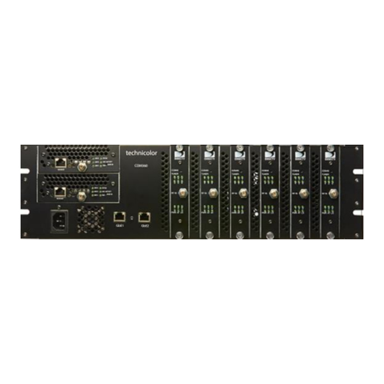
Gigabit Ethernet Ports Ventilation Grates Figure 2 - COM2000 Front View The AC input connection shown at the bottom left provides power to the COM360 chassis. The two Gigabit Ethernet ports on the right of the power cord allow for direct connections to other devices such as an ATSC-8, external media, edge QAM, Ethernet switch, management PC and allows any additional chassis in the system to be interconnected. -
Page 17: Figure 3- Com2000 Rear View
Exhaust Fan Exhaust Fan Figure 3- COM2000 Rear View The COM360 chassis also contains two 5-inch exhaust fans to provide cooling to the system. Airflow is pulled through the ventilation grates on the front of the COM360 chassis across the COM46 cards and out the back. -
Page 18: Com46 Card
4.2 COM46 Card The COM46 card, shown in Figure 4 below, is a customized DIRECTV receiver with a built-in smart card and has been specifically designed to meet the unique requirements of the Lodging and Hospitality markets. The COM46 is an 8 channel receiver capable of receiving up to 8 HD or SD streams from a single SWiM output, removing the NDS conditional access system, and adding the Pro:Idiom content protection DRM. - Page 19 Each COM46 card contains an RF input, 12 indicator lights, a recessed reset button, and thumbscrews on either end. The cards are hot-swappable, allowing one card to be serviced independently of the other cards. In order to remove a card, simply loosen the thumbscrews that secure the card in place and pull it straight out of its slot.
-
Page 20: Com46-Flx Card
The COM46-FLX card, shown in Figure 5 below, is a variant of the standard COM46 card that is only capable of receiving standard definition programming as shipped from the factory. It can be upgraded to receive HD programming through installation of an upgrade license key provided by Technicolor or DIRECTV. -
Page 21: Qam6 Overview
12 QAM modulators in addition to the front 100mbps Ethernet port, which can be used to manage the COM2000 system. Each QAM channel can carry up to 3 HD or 8 SD DIRECTV video channels. A COM360 chassis fully populated with COM46 receivers (48 HD channels total) requires 16 QAM channels (3 HD channels per QAM). -
Page 22: Figure 7- Qam6 Installation
To complete an upgrade of the FPGA firmware a power off reset is required. The current firmware version is listed under HW Version. It is currently 0.16 and rarely changes. The 10/100 Ethernet Interface on the front can be used to manage the COM2000 System. Figure 7- QAM6 Installation The QAM6 board plugs into one of the two available card slots on the left side of the chassis. -
Page 23: Pre-Installation
Pre-Installation The COM2000 System is quite a bit different from the DIRECTV set-top box (STB) receiver traditionally used in these installations. This is because the COM1000 does not natively decode any audio or video, instead relying upon other devices in the system to decode and display the MPEG streams it produces. -
Page 24: Pre-Installation Site Requirements
5.3 Pre-Installation Site Requirements Site Survey Prior to installation, it is recommended that a detailed site survey is conducted. Listed below are some key points to check and plan for during and after site survey ODU Location o Determine an area with clear line of site to the southern sky. o Determine distance from the dish to head end and plan for cable selection and routing appropriately. -
Page 25: Channel Lineup
QAM tab of the COM2000 web interface. The COM2000 can modulate up to three high definition programs on one 6MHz QAM channel. It is a best practice not to combine higher bandwidth local, sports and premium channels on the same QAM channel. -
Page 26: Installation Guidelines
5.7 Installation Guidelines Here are a few guidelines to keep in mind when installing the COM2000 system that will minimize the potential problems that the system could be expected to encounter. The optimum RF levels at the input of a SWiM module are -30 to -50 dBm per transponder. -
Page 27: Directv Activation
If they do not, check the CAM log for any new error messages. Under normal circumstances, the COM46 cards in the COM2000 system should never lose their authorization. However, like a normal DIRECTV set-top box, if a card is left unconnected from the DIRECTV network for an extended period, it will lose its authorization. -
Page 28: Getting Started
Getting Started 6.1 Assembly Carefully unpack and install the QAM6 and COM46 cards in the COM360 Chassis as shown in Figure 8. Be sure to line up the cards with the guides in the chassis. A #10 Torx driver is required to secure the QAM6 in the COM360 chassis as shown in Figure 9. Figure 8 - Installation of the QAM6 Figure 9 - Securing the QAM6 in the COM360 w w w . -
Page 29: Setting Up Multiple Chassis
6.2 Setting up Multiple Chassis For installations requiring more than one COM360 chassis each chassis will need to be assigned a unique chassis ID. The COM360 chassis has a default setting as chassis one. Chassis identification is configured via a dipswitch on the backplane circuit board. To access the switch you will need to remove the rear cover of the COM36 as shown in Figure 10. -
Page 30: Figure 12 - Dipswitch Settings For Multiple Chassis
Set the chassis ID by changing the dipswitch settings as shown below in Figure 12. The default IP address of each COM46 card in a system is determined by the chassis ID and slot number the card is installed in. The formula for determining this address is 192.168.3.[1 + (chassis ID X 16) + slot number]. -
Page 31: The Com2000 Web Interface
Each COM46 card contains a basic web-based application that provides an easy means to control and configure the COM2000 system. This tool can be accessed by entering the IP address of one of the COM46 cards in the system into a web browser’s address bar. Clicking on the Technicolor logo on the Introduction Page in Figure 13 will open the COM46 Overview page. -
Page 32: The Overview Page
The Overview Page shown below in Figure 14 provides a streamlined method for initial configuration and quick status monitoring of the COM2000 system using a series of pulldown menus to configure each card. It shows the same status information carried on the Discover page as well as the encryption method being used by each channel and overall card status. -
Page 33: Figure 15 - Encryption Settings
Hyperlinks - The IP hyperlink(s) in the QAM Summary below the Command tabs will take you to the associated QAM tab. The hyperlinks in the Chassis, Slot, and Tuner columns allow you to collapse the display for the selection so that multiple cards and chassis can be more easily displayed. -
Page 34: Figure 16 - Channel Drop Down Menu
Channel - Figure 16 shows the Channel dropdown feature. This allows you to assign a tuner to any channel carried in the guide, including channels that the account is not authorized to receive. Figure 16 - Channel Drop Down Menu ... -
Page 35: Figure 18 - Major/Minor Ch Or Ip And Port Settings
Bitrate - Figure 19 shows the Bitrate filed. It displays a snapshot of the bitrate associated with the selected QAM channel. If the destination IP is not a Technicolor QAM modulator card, this field will read 0.0 and will be highlighted in red. -
Page 36: Discover Page
7.2 Discover Page Most configurations on the COM2000 system can be done via the Overview page previously discussed. However, there are redundant controls in the Discover page in addition to controls for advanced features and troubleshooting. This section will detail all the controls available from the Discover page. The COM46 card issues a discovery call for all other COM46 (and COM24) cards in the system, and then populates a table with some basic information on current tuning parameters and RF signal levels. -
Page 37: Explanation Of Discover
COM46. If the Strength is low, it will be highlighted in yellow and if the Strength is very low, it will be highlighted in red. For optimum performance of the COM2000, this value should be somewhere between -25 and -55. -
Page 38: The Tune Command
7.4 The Tune Command The Basic Tune screen shown in Figure 22 can be accessed by clicking the ChannelNumber link in the Channel column of the Discover page (see Figure 21.) You can also access the Basic Tune screen of any given COM46 card and tuner combination by clicking the channel name/number hyperlink in the Channel column on the Refresh or Display pages. -
Page 39: Advanced Tune Screen
QamMinor - The QAM6 output QAM minor channel number. This corresponds to the subchannel number (e.g., 2 in the channel number 13.2 or 13-2 is the sub-channel number). Major_Number - This field is equivalent to the DIRECTV channel number you tune to on a typical DIRECTV tuner. - Page 40 A unique tuner can be identified by chassis number, slot number, tuner number, and IP Address. Chassis - This value shows the Chassis number of the COM360 that holds the COM46 card you are currently tuning. Slot - This value shows the Slot number within the COM360 chassis that holds the COM46 card you are currently tuning.
- Page 41 Stream_ID - This field is optional, and allows a unique identifier to be applied to every video stream produced by the COM2000 system. The allowable values for this field are any whole number between 1 and 65535. The default value is 111. To enable a second audio stream set the Stream_ID to 54000.
-
Page 42: Com46 Informational Status
7.6 COM46 Informational Status The information shown in Figure 24 below is one of the subsections available on the Advanced Edit page. Figure 24 - "Info" Section of the Advanced Edit Page This section provides a selection of many key indicators to the operation of the COM46 card. It acts as a concise index to the characteristics of each individual COM46 card according to its status and user-defined settings. -
Page 43: Figure 25 - Network Id And Frequency Index
Frequency_Index - This field reports the frequency index corresponding to the channel the tuner is currently set to. Frequency_Index is a 0 base value. Transponder #s on meters and IRD are 1 base. To determine the channel’s transponder add 1 to the Frequency Index. o The table below in Figure 25 details the Network_ID and corresponding satellite. -
Page 44: Com46 Led Control Feature
7.7 COM46 LED Control Feature The information shown in Figure 26 below is one of the subsections available on the Advanced Edit page. Figure 26 - LED Control This section gives you the ability to assume control of the PWR LED temporarily. This feature can help you easily identify a specific card within a chassis if there is ever any doubt about which card you are accessing. -
Page 45: Figure 28 - Cam Log Report
Under normal circumstances, an authorized card will produce a very short CAM log file that looks like the image shown in Figure 28 below. If, however, there are issues with the card’s authorization, you will see messages that look more like this: 0 0 0: CARD_INSERTED 1 9 727: 727 - Program Not Available in Your Area (Service Blacked... -
Page 46: Com46 Software Reset
7.9 COM46 Software Reset The information shown in Figure 29 below is one of the subsections available on the Advanced Edit page. Figure 29 - Reset Interface This section allows you to initiate software reset on the card identified in the “CardIP” field. This is sometimes helpful in situations where a card has become non-responsive. - Page 47 (all others are for development purposes only): 1 = MT – This option allows you to upload the special MediaTune authorization and channel guide files. See COM2000 Technical Support - Mediatune Installation Folder on the Technicolor / MCS website for details.
-
Page 48: Com46 User Configuration Options
7.11 COM46 User Configuration Options The information shown in Figure 31 below is one of the subsections available on the Advanced Edit page. Figure 31 - User Config Interface This section gives you the ability to customize select features of the COM46 cards to better suit your application. - Page 49 4 = Fixed - In this mode the user sets the Base_IP, Subnet and Gateway fields. All fields MUST be set. A Gateway MUST be defined regardless of it being there or not for this mode. Once you set the card IP you must reboot the card. 8 = No Change - This setting does not actually represent a separate mode, but rather acts as a way to tell the COM46 card that you would like it to continue using whatever mode it is currently using.
-
Page 50: Com46 "Direct Tune" Feature
Edit page. This section gives you a method to force a tuner to a particular satellite and transponder pair. This ability can especially useful when attempting to track and isolate RF problems with the COM2000 system. The data required to perform this operation can be gathered from the basic “Tune” interface shown in above. -
Page 51: Using The Vidplay Feature
7.14 Using the VidPlay Feature The VidPlay feature will stream video files from a NAS portable hard drive similar to a Western Digital My Cloud. Enter the IP:Port information and the name of the files to be played. Figure 34 - Vid Play 7.15 Using the COM46 “Simulcrypt”... -
Page 52: Using The Com46 Rest Feature
Figure 36 - REST 7.17 Displaying COM2000 Status By clicking the Display hyperlink at the top of any COM2000 web interface page, you can see the information last obtained from a Discover or Refresh with the signal status of all cards in the system as shown in Figure 37 below. -
Page 53: Pairing Info
7.18 Pairing Info By clicking the PairingInfo hyperlink at the top of any COM2000 web interface page, you can quickly evaluate the authorization status of all cards in the system. In the example shown in Figure 38, card 6 is activated but not paired with the CAM card. A follow up call to DIRECTV activation will be required. - Page 54 RID - This field reports the DIRECTV Receiver ID, or RID. This value is the first of two parameters required to obtain authorization on the DIRECTV network. CAM_ID - This field reports the DIRECTV CAM ID. This value is the second parameter required to obtain authorization on the DIRECTV network.
- Page 55 Following is a brief description of the relevant fields on this page: Usage - This field allows you to select which type of file transfer you wish to undertake for a particular card. The available options are shown below. It should be noted that when selecting any option other than ‘2’, the card will appear to go through the usual software update cycle, but that it will revert to the current build of code once it has rebooted.
-
Page 56: Tune All Command
7.19 Tune all Command The information shown in Figure 40 below is the result of clicking the TuneAll hyperlink at the top of the COM2000 web interface page. Figure 40 - COM46 Tune All w w w . t e c h n i c o l o r . c o m / m c s... - Page 57 This section provides a practical way to configure an entire COM2000 system with minimal effort. In order to use this feature, you can start by copying and pasting the information provided at the bottom of the browser page (below the Submit Query button) either directly into the text field provided or into your text editor of choice, and then modifying it as indicated by the guide comments located above the text field.
-
Page 58: Refreshing The Com2000 Display
7.20 Refreshing the COM2000 Display Figure 41 below is the result obtained by clicking the Refresh link at the top of any COM2000 web interface page. Please note that this table is filled in with data obtained during execution of the Discover command. -
Page 59: Sysinfo
7.21 SysInfo By clicking the SysInfo hyperlink at the top of any COM2000 web interface page, you will access the page shown below. This table gives you the ability to identify a number of different unique identifiers for every COM46 card as well as to identify which card in the chassis, if any, has been assigned the generation of the Electronic Program Guide (EPG.) -
Page 60: Healthinfo
By clicking the HealthInfo hyperlink at the top of any COM2000 web interface page, you will access the page shown below in Figure 43. The data available here gives you an indication of the overall health of the COM2000 system, and can be used to identify potential problem areas at a glance. - Page 61 CardIP – This field shows the IP address of the COM46 card that resides in the chassis and slot combination to its left. Card_Temperature – Deprecated in the COM46. IC_Temperature – This field reports the internal temperature of the main processor chip on the COM46 card.
-
Page 62: Syslogs
The information shown below is the result of clicking the Syslog hyperlink at the top of any COM2000 web interface page. Note that the syslog will only show the last 500 lines of messages from the card you are currently logged into. -
Page 63: Electronic Program Guide And Psip
COM2000, an analog SMATV system, or over-the-air signals. Another feature of the COM2000 EPG is the ability to upload and playback welcome screen images that will play direct from the COM46 card. - Page 64 The EPG is created in such a way that it provides the viewer with what appears to be an auto- scrolling channel listing. It is essentially a dynamic MPEG video stream made up of still images of the current programming. It moves down the list of assigned channels every 2.5 seconds, creating a constant cycle, showing nine channels at a time.
-
Page 65: Getting Started With Epg
8.2 Getting Started with EPG In order to access the EPG setup screen shown in Figure 45 below, simply click the EPG hyperlink at the top of any COM2000 web interface page. Figure 45 - COM2000 EPG Page Following is a brief explanation of each field available on the EPG page as shown above: DestIP This field represents the IP address of the device you wish to send the EPG data to. - Page 66 This tells the guide whether to pull the data for the HD or the SD version of a particular channel. The default behavior for the COM2000 is to look for HD channels, so this setting allows you to add SD channels to the EPG if needed. Please note that on submission, the EPG will default to ‘hd’...
- Page 67 Non-DIRECTV channel (channel name Local) Note: The actual content could come from the COM2000, a separate analog SMATV system, or even from on-air, as long as the channel is available in DIRECTV’s lineup. w w w . t e c h n i c o l o r . c o m / m c s...
- Page 68 Figure 46. Figure 46 - COM2000 EPG Page (Configured) w w w . t e c h n i c o l o r . c o m / m c s...
-
Page 69: Configuring The Epg
8.3 Configuring the EPG The screen shown in Figure 47 below is the result of clicking the EpgLoad button located at the bottom of the EPG screen. Doing this provides a convenient starting point for building an EPG for your system. To set a custom channel map change the RF channels listed to the preferred channel ring. -
Page 70: Figure 48 - Guide Channel
offset, and modify the lineup as needed. You may also upload a logo for the property that will be displayed in the upper right corner of the EPG. When modifying the EPG channel lineup, the channels can be entered in any order, as the COM46 card will automatically sort them by channel number when it builds the guide. -
Page 71: Logo Upload
8.4 Logo upload The COM46 has a built-in facility for superimposing a property’s logo into the upper right corner of the EPG. Should the System Operator express an interest in providing such a logo, it is entirely up to the property to employ someone to do so. It is recommended that you work with someone in either the property’s Branding or Corporate Identity department or with a graphics professional in order to obtain an image that is in the proper format to be added to the EPG. -
Page 72: Welcome Screen
Welcome Screen The welcome screen feature allows the creation and playback of up to 10 static images on a QAM channel. Each channel will use the EPG function on a card not currently being used for EPG. The images will change approximately every 15 seconds. EPG on each COM 46 card can send an image to a different QAM port. -
Page 73: Figure 52 - Using Microsoft Paint To Size Welcome Screen
Next open the file in Microsoft Paint. Use the Resize and Skew feature to set the image to 720X480 as shown in Figure 52. 1. Select Resize by Pixels 2. Set Horizontal to 720 3. Set Vertical to 480 4. Uncheck Maintain Aspect Ration 5. -
Page 74: Uploading Welcome Screens To Com 2000
Image will resize to correct format as shown in Figure 53. Figure 53 - Correctly Sized Welcome Screen Image Save file!!! Repeat the above procedure to create multiple screens, welcome2, welcome3, etc. Note file names must be lower case with no spaces. 9.2 Uploading Welcome screens to COM 2000 Determine Card to use: Card must be running 03.02.21 software. -
Page 75: Figure 55 - Upload Welcome Screen Files To Internal Tftp
Figure 55 shows the Browser Upload function. Upload file to the card FTP from the Pairing Info tab. Figure 55 – Upload Welcome Screen Files to internal TFTP w w w . t e c h n i c o l o r . c o m / m c s Page 75... -
Page 76: Figure 56 - Upload Welcome Screen Image To Epg
Select EPG tab 1. Enter the IP address and port# of the QAM you want to use to stream the welcome screen. 2. Enter 2 in the ignore DST field. 3. Enter the IP address of card you are using for FTP 4. -
Page 77: Figure 57 - Adding Welcome Screen To Epg And Psip
If you are using PSIP or would like the welcome screen displayed in the EPG log into the card running EPG and add the channel to the EPG information as shown in Figure 57. Figure 57 - Adding Welcome Screen to EPG and PSIP w w w . -
Page 78: Figure 58 - Verify Welcome Screen Is Streaming
You can verify the screens are streaming by checking for data on the corresponding QAM port as shown in Figure 58 below. Figure 58 - Verify Welcome screen is streaming Your Welcome screen should now be playing on the TV. Screens scroll every 15 seconds. To disable the Welcome screens set the DST field to 0. -
Page 79: Qam6
The board provides 12 QAM modulators in addition to the front 1 0 0 m b p s Ethernet port, which can be used to manage the COM2000 system. Each QAM channel can carry up to 3 HD or 8 SD video channels. When shipped from the factory the QAM6 boards will only permit six QAM carriers to be active at a time. -
Page 80: Qam6 Settings And Configuration
10.2 QAM6 Settings and Configuration The QAM6 card is controlled by any of the COM46 cards via Ethernet. The QAM6 card has a fixed IP address = 192.168.6.“Chassis ID” + 1. An arbitrary alternate address can be assigned. QAM output channels have a destination port of QAM Channel *16 + subchannel number. The screen in Figure 60 shows the status of each channel. - Page 81 QAM6 IP Address: Chassis 1 QAM1 Base RF channel- Each group of 4 must be adjacent channels Sub channel -1, -2… Port = base + sub 17,18,19… Bandwidth per port/subchannel Total bandwidth per QAM Total combined bandwidth QAM6 software version Total QAM License count 1 activates RF carrier Alternate IP address...
- Page 82 tftpFilename - This field sets the filename of the new SW image. Reset - This field executes a SW reset of the QAM6. It is almost user transparent but will create a brief video glitch on the channels it is modulating. Application Notes: ...
-
Page 83: Qam Log
10.3 QAM LOG When troubleshooting QAM6 issues, click on the QAM Log button to see the QAM6 system log. This log is mainly for Technicolor technical analysis but a short summary is: A = Arp reply bad(#) = Discarded # number of unexpected Ethernet packets. -
Page 84: Software Upgrade Procedures
In most cases the software will need to reside on a local machine networked to the COM2000. If you have a VPN route to the system a remote computer should work to transfer the software to the COM46 TFP. -
Page 85: Using The Com46 As A Tftp Server
11.2 Using the COM46 as a TFTP server A COM46 in the chassis can be configured to act as a local sever for SW and license upgrades using the Browser Upload feature in the Pairing Info page as shown in figure 58 below. To upload a new software version, use the Choose File button to find the firmware file on the host system or enter the filename into the field. -
Page 86: Performing Software Upgrades
If the upload is successful, the filename will appear under the line “TFTP server at xxx.xxx.xxx.xxx current files:” As shown in figure 59 below. Once the selected file has been uploaded, the rest of the update procedure is the same as with the COM24/COM1000 as described in Section IP address of FTP card... - Page 87 To use the single card upgrade method, go to the File Transfer section of the Advanced Tune page. See Figure 64 below. Enter the IP address of the server and filename of the new image as indicated above and press the Submit button.
- Page 88 If one desires to update all of the COM46 cards in a chassis (multi-card upgrade method), then all upgrade fields would be checked as shown in Figure 61 below. Figure 65 - Multi Card COM46 SW Update The results of the upgrade in Figure 61 are shown below in Figure 62. Figure 66 - Multi Card Upgrade Results Once the software has loaded the card will reboot.
-
Page 89: Upgrading A Com46-Flx From Sd To Hd
11.4 Upgrading a COM46-FLX from SD to HD Upgrading the COM46-FLX from SD only to HD requires prior authorization from DIRECTV. Once an upgrade license has been authorized, it is applied using the same method as the SW upgrade described above. In Figure 67 the filename will be the name of the license file, e.g. -
Page 90: Upgrading Qam6 Software
11.5 Upgrading QAM6 Software Upgrading the software for the QAM6 is similar to updating the firmware for the COM46 and except for the following differences: QAM6 upgrade is TFTP only. Ftp is not available. Only one QAM6 can be updated at a time. ... -
Page 91: Qam6 Reset
Figure 71, indicating that the card has completed the download. Reset the QAM6 by removing power from the chassis or removing the QAM6 from the chassis and reinserting it. Do not reset the QAM6 until the blue light flashes! Figure 71 - QAM6 Reset After Software Upgrade © 2012 Technicolor. All Rights reserved... -
Page 92: Modulation Of External Video Sources
Cloud drive will store MPEG2 VBR media with the capability of assigning an IP destination Video Servers – Video Servers such as the ZyCast HDIP-930 will convert media from HDMI or Component Video sources to an IP stream which can be directed to the COM2000 QAM6 card. -
Page 93: Diagnostics
Diagnostics When it comes to troubleshooting your COM2000 system, the COM46 card has a few built-in mechanisms that can assist you. Each of these can be very helpful in diagnosing general issues associated with system status and card connections that will be covered in the following sections. -
Page 94: System Startup
It is important to understand the behaviors associated with the execution of normal procedures before you can effectively diagnose any card issues. This section covers the sequence of events that occur in a COM2000 system at boot-up. The COM46 card goes through four steps at startup: 1) Self test This includes SWiM channel lock. - Page 95 The COM46 cards take between 2 and 3 minutes to reach a fully functional state after a reboot or power-up. The status of the card can be tracked during this time by observing the behavior of the LEDs. Normal LED behavior during startup is listed below in Figure 73. Approx.
-
Page 96: Normal Operation
13.4 Normal Operation When operating under normal circumstances, there are a few characteristics you can expect to see in LED behavior. The PWR LED should always be lit. If the PWR LED is not lit and the chassis is powered, check the COM46 for proper installation in the chassis. -
Page 97: Software Upgrade
13.5 Software Upgrade During a COM46 software upgrade sequence the card will upload the new image from the IP address set in the ‘Server_IP_Address’ field for a software upgrade. The new SW image is then tested to verify it is a valid COM46 image and finally written to the card’s flash memory. -
Page 98: Network Connectivity Indicators
You have entered the correct destination IP for the PC handling the update. You have correctly entered the update file name. The directory path and filename do not exceed the maximum limit of 200 characters. 13.6 Network Connectivity Indicators There are two Ethernet jacks on the face of the COM360. -
Page 99: Troubleshooting
Troubleshooting The most common problems encountered with the COM2000 systems are due to poor RF signal conditions or to bad or loose connections. Before moving on to detailed troubleshooting of any problem, you should check the following: All necessary connections (power supply, Ethernet, and coaxial cables) are fully plugged or screwed in. - Page 100 VLC Media Player. Select “Media” from the main menu, and then select “Open Network Stream” from the dropdown menu that appears as shown in Figure 76 below. Figure 76 - VLC Open Network Stream In the new window shown in Figure 77, set the network URL to something like “udp://@:17”, where “udp”...
- Page 101 If you have set up all your connections as directed, VLC Media Player should start streaming video output from channel 100. The resulting screen should look similar to the one shown in Figure 78. Figure 78 - Streaming Video with VLC w w w .
-
Page 102: Fixing An Unresponsive Card
14.2 Fixing an Unresponsive Card If, in the event of a catastrophic power fail or other “glitch” event during software updates , the COM46 card becomes unresponsive. It is possible to reprogram the card with a working copy of the flash image. The TFTP server described in this manual, Tftpd32, also contains a BOOTP server. - Page 103 In the DHCP settings tab, enter the filename of the application image in the ‘Boot File’ field and click OK. Next make sure that the DHCP option is checked in the ‘GLOBAL’ tab and hit OK. The Tftpd32 application will need to be restarted after making these changes. Refer to Figure 80 below.
-
Page 104: Preventing Pro:idiom Key Loss
Preventing Pro:Idiom Key Loss There are two mechanisms which may cause Pro:Idiom key loss in some commercial television sets that have been identified to us by LG Unapproved mapping or remapping of PIDs Off air (OA) ATSC receivers may use PIDs which conflict with PIDs in use in Pro:Idiom licensed systems. -
Page 105: Best Practices To Avoid Key Loss
A non-P:I, non-off air channel MUST be placed in the channel map between any broadcast channel and a Pro:Idiom protected channel. The COM2000 EPG, Home Screen or locally inserted channels makes a good buffer. Analog SMATV channels can also be used as buffers. -
Page 106: Edgeqam Pid Remapping
A number of edgeQAM products have been designed specifically to work in Pro:Idiom systems and are known to correctly manage Pro:Idiom Key Management message PIDs including but not limited to Technicolor’s QAM6 and Video Propulsion’s Floodgate. Check with other manufacturers regarding their equipment. - Page 107 Reuse of the same PID value is a major contributing factor in key loss and should be avoided when mapping out the IP and port scheme used to send the data to the QAM. DO NOT USE THE FIRST TWO UDP PORTS AVAILABLE OVER AND OVER AGAIN.
- Page 108 Figure 84 shows correct PID mapping on a Harmonic QAM Figure 84 - Correct PID Remapping Contact your distributor or the Edge QAM manufacturer for further support. w w w . t e c h n i c o l o r . c o m / m c s Page 108...
-
Page 109: Technicolor Atsc-8 Users Guide
Technicolor ATSC-8 Users Guide w w w . t e c h n i c o l o r . c o m / m c s Page 109... -
Page 110: Introduction
This document describes the process and procedures for integrating the ATSC-8 product with the COM2000 digital head-end system. The ATSC-8, available from Technicolor, will allow for the reception of over-the-air broadcasts of digital broadcasts and output of this content over an Internet Protocol (IP) output. -
Page 111: Getting Started
16.4 Getting Started Antenna Selection Installation of the ATSC8 is assumed to be done by trained installers with a strong understanding of off-air antenna and distribution systems. For reference some information is offered below: Some issues to consider when planning an installation and selecting and antenna: Determine local off air channels There are multiple web sites which will provide information on available OTA channels by market. - Page 112 Determine available channels As part of the site survey connect a TV to an antenna and auto-program in off air mode. The TV will lock onto all available channels. Monitor all channels you plan on using to verify consistent signal quality. Document all channel information in a workbook file similar to the one below: QAM PORT PLUS 256...
-
Page 113: Atsc-8 Programming
16.6 ATSC-8 Programming The ATSC-8 can be programmed in one of two fashions: 1. Each tuner can generate one off-air channel that can be mapped using the COM2000 EPG / PSIP functions. Pros Cons Channels can be mapped in the EPG and... -
Page 114: Atsc-8 Installation
16.7 ATSC-8 Installation 75 ohm Antenna inputs Ethernet connections Power Switch Power Cable Figure 85 - ATSC-8 Back Panel A B C D 1 2 3 4 5 6 7 8 Figure 86 - ATSC-8 Front panel Front LED Indicators Power/Network –... -
Page 115: Connection To The Com2000
The ATSC-8 is rack mountable and can be easily mounted in the same location as the COM2000 system. It is recommended that at least 1RU of space be left between the ATSC-8, the COM2000, and any other components so that each component will receive good air-flow in the mounting location. - Page 116 Antenna splitter Figure 89 - ATSC Connection Diagram w w w . t e c h n i c o l o r . c o m / m c s Page 116...
-
Page 117: Check / Update The Atsc-8 Firmware Version
Note: COM46 software must be set to version 3.2.19 or newer. Internal to the ATSC-8 are 4 tuner modules. To properly interact with the with the COM2000 interface the firmware should always be set to version 20120405. The firmware and the HDHomeRun software utility required to update the firmware are available on the Technicolor After Market Support web site, or through your distributor. - Page 118 Click Open and the firmware will load into the HDHomeRun utility as shown in figure 86 below: Figure 87 - Loading firmware in teh HDHomeRun Utility Click on the Flash button next to each tuner. When successfully completed the Firmware version will be displayed as shown in figure 87 below: Figure 93 - HDHomeRun Firmware Load w w w .
-
Page 119: Configuring The Atsc-8
16.12 Discover the IP Addresses of the ATSC Tuner Modules When the ATSC-8 is shipped from Technicolor, it will be in DHCP mode and expect to get assigned an IP address from a router. Since our connection diagrams and common installation practices do not include a router or DHCP server, the IP addresses may not be assigned. -
Page 120: Changing The Ip Addresses Of The Tuners
You may change the IP addresses of the tuners to a range within the same IP configuration of the COM2000 by using the SET button on the ATSC page. You must first type in the base number for the assignment, then hit the SET button. For instance, if you’d like the IP addresses to be in a range starting at 192.168.3.50, then use 192.168.3.50 as the base address. - Page 121 From our previous discovery, we showed both the known IP addresses and the AutoIP addresses for each of the 4 addressable tuners in the ATSC-8. When making the requested IP address change, each device receives 2 commands to change the IP with the second command resulting in the change.
-
Page 122: Loading Data From The Tuners
As shown in Figure , from the ATSC page, you can click the LOAD button to have the device send a report back to the COM2000 interface to see what the current configuration is set to. Once you have run the load function, return to the ATSC page to see the results. - Page 123 Each listing in the tune table will need all the required fields entered. Figure 101 below is an entry along with a description of what each field contains. 192.168.3.54 0 9 8.1 192.168.6.2 35 192.168.3.54 = IP address of the tuner to be set. 0 = Tuner index.
-
Page 124: Query Command
16.16 QUERY Command The ATSC-8 is able to Query the tuned channels once they have been set up so you can view the signal strength of each frequency. This could be especially helpful if you aren’t seeing channels that you’d expect to or need to adjust your input antenna. Lock = none Signal Strength Signal Quality %... -
Page 125: Adding Psip Data For Atsc-8 Channels
16.17 Adding PSIP Data for ATSC-8 Channels For many COM2000 users, adding PSIP data to change the virtual channel number and to include program data is a vital part of the COM2000 deployment. For more examples and configurations regarding PSIP and EPG, please see the EPG section 8. -
Page 126: Addendums
Technicolor's website at the following address: http://www.technicolor.com/en/hi/minisites/open-software or at another address as Technicolor may provide from time to time. If and where applicable, depending on the terms of the applicable Open Source Software licenses, the source code of the Open Source Software is available for free upon request.
Need help?
Do you have a question about the COM2000 and is the answer not in the manual?
Questions and answers