Table of Contents
Advertisement
Quick Links
DMP-BD91GN
Model No.
DMP-BD81PU
DMP-BD81GA
DMP-BD81GC
DMP-BD81GN
DMP-BD81GT
DMP-BDT160GA
DMP-BDT160GN
DMP-BDT160GW
DMP-BDT161GC
Colour
(K).......................Black Type
Panasonic Corporation © 2014.
Unauthorized copying and distribution is a violation
of law.
ORDER NO.CHM1404003CE
Blu-ray Disc Player
Advertisement
Table of Contents

Related Manuals for Panasonic DMP-BD81PU


Summary of Contents for Panasonic DMP-BD81PU
- Page 1 ORDER NO.CHM1404003CE Blu-ray Disc Player DMP-BD91GN Model No. DMP-BD81PU DMP-BD81GA DMP-BD81GC DMP-BD81GN DMP-BD81GT DMP-BDT160GA DMP-BDT160GN DMP-BDT160GW DMP-BDT161GC Colour (K).......Black Type Panasonic Corporation © 2014. Unauthorized copying and distribution is a violation of law.
-
Page 4: Table Of Contents
TABLE OF CONTENTS PAGE PAGE 1 Safety Precautions -----------------------------------------------5 1.1. General guidelines -----------------------------------------5 1.2. Caution for fuse replacement ---------------------------5 2 Warning --------------------------------------------------------------7 2.1. Prevention of Electrostatic Discharge (ESD) to Electrostatic Sensitive (ES) Devices ---------------7 2.2. Precaution of Laser Diode -------------------------------8 2.3. -
Page 5: Safety Precautions
1 Safety Precautions 1.1. General guidelines 1. When servicing, observe the original lead dress. If a short circuit is found, replace all parts which have been overheated or damaged by the short circuit. 2. After servicing, see to it that all the protective devices such as insulation barriers, insulation papers shields are properly installed. - Page 6 1.2.1. Micro Fuse conducting check This unit uses the Micro Fuse. Check the Micro Fuse conducting using the Tester at the check points below.
-
Page 7: Warning
2 Warning 2.1. Prevention of Electrostatic Discharge (ESD) to Electrostatic Sensitive (ES) Devices Some semiconductor (solid state) devices can be damaged easily by static electricity. Such components commonly are called Elec- trostatic Sensitive (ES) Devices. Examples of typical ES devices are integrated circuits and some field-effect transistors and semi- conductor "chip"... -
Page 8: Precaution Of Laser Diode
2.2. Precaution of Laser Diode... -
Page 9: Service Caution Based On Legal Restrictions
2.3. Service caution based on legal restrictions 2.3.1. General description about Lead Free Solder (PbF) The lead free solder has been used in the mounting process of all electrical components on the printed circuit boards used for this equipment in considering the globally environmental conservation. The normal solder is the alloy of tin (Sn) and lead (Pb). -
Page 10: Service Navigation
3 Service Navigation 3.1. Combination of Multiple Pressing on the Remote Control Press multi-buttons (in combination) on the remote control simultaneously for operations, such as initialization or service mode, etc. 3.2. The display position of TV Special modes display of this unit changes to TV display from the original FL display. 3.3. - Page 11 3.3.1. Disclosure mode (Combination of multiple pressing: [OK] [Blue] [Yellow]) Press and hold [OK] [Blue] [Yellow] on the remote control simultaneously for 5 sec., then "00RET" is displayed on TV display window. 3.3.2. Nondisclosure mode 1 (Combination of multiple pressing: [6] [7] [Yellow]) Press and hold [6] [7] [Yellow] on the remote control simultaneously for about 5 sec., then "50RET"...
-
Page 12: How To Update Firmware
3.3.3. Nondisclosure mode 2 (Combination of multiple pressing: [5] [9] [Red]) Press and hold [5] [9] [Red] on the remote control simultaneously for about 5 sec., then "70RET" is displayed on TV display window. 3.4. How to Update Firmware The firmware of the unit may be renewed to improve the quality including operational performance and playability. Make sure to refer the following procedure when performing version-up. - Page 13 3.4.2.1. Updating firmware via the internet Occasionally, Panasonic may release updated DO NOT DISCONNECT the unit from the AC firmware for this unit that may add or improve the way a feature power or perform any operation while the update takes place.
- Page 14 3.4.2.2. Updating firmware using the USB device When updating firmware using USB device, perform following procedures. (When using CD-R instead of USB device, perform same procedures) 1. Download the latest firmware file of the unit The latest firmware required for version-up can be downloaded from "Support Information from NWBG/VDBG-PAVC" web-site in "TSN system".
- Page 15 3. Update the unit (1)Turn the unit power on. (2)After the home screen is displayed, insert the USB device stored downloaded latest firmware file to front USB port of the unit.(or set the CD-R into the unit and playback it.) (3)The screens are displayed as below.
-
Page 16: Specifications
4 Specifications +RW: Video(*1), AVCHD format(*1) DVD-Video: DVD-Video format CD-Audio: CD-DA CD-R/CD-RW: CD-DA, JPEG(*2), Power supply: AC110V, 60Hz (BD81GT) MPO(*2)(BDT160GA/GW/ AC110V-240V, 50/60Hz (BD81PU) GN,161GC),MP3(*2), MKV(*2, AC220V-240V, 50Hz (BD91GN/ *5), WAV(*2), FLAC(*2), 81GN,BDT160GN) AAC(*2),WMA(*2),Xvid AC220V-240V, 50/60Hz (BD81GA/ *1: Finalizing is necessary. GC,BDT160GA/GW,161GC) *2: ISO9660 level1 or 2(except for extended formats), Joliet. - Page 17 Regional Code: DVD: #2 (BD81GC) DVD: #3 (BD91GN/81GA/GN/ GT,BDT160GA/GN/GW,161GC) DVD: #4 (BD81PU/81GN/ BD91GN/BDT160GN) BD: Region A (BD81GA/GC/ GT,BDT160GA/GW,161GC) BD: Region B (BD81GC/81GN/ BD91GN/BDT160GN) Dimensions: 312mm(W) [Approx. 12 5/16''(W)] 43mm(H) [Approx. 1 11/16''(H)] 180mm(D) [Approx. 7 2/16''(D)] Mass: Approx. 1.0 kg ( 2.2 lbs) Solder: This model uses lead free solder(PbF).
-
Page 18: Location Of Controls And Components
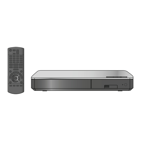
5 Location of Controls and Components... -
Page 19: Operating Instructions
6 Operating Instructions 6.1. Taking out the Disc from BD-Drive Unit when the Disc cannot be ejected by OPEN/CLOSE button 6.1.1. Forcible Disc Eject 1. Turn on the power, press and hold [OK], [B] and [Y] on the remote control at the same time for more than 5 seconds. "00RET"... -
Page 20: Service Mode
7 Service Mode 7.1. Special Mode Setting and Service mode 7.1.1. Self-Diagnosis Functions Self-Diagnosis Function provides information for errors to service personnel by “Self-Diagnosis Display” when any error has occurred. U** and F** are stored in memory and held. You can check latest error code by transmitting [0] [1] of Remote Controller in Service Mode. Automatic Display on FL will be cancelled when the power is turned off or AC input is turned off during self-diagnosis display is ON. - Page 21 Error Code Diagnosis contents Description Monitor Display Automatic TV display Initialization error When initialization error is detected after start- No display No display ing up main microprocessor, the power is turned off automatically. The event is saved in memory. Drive hardware error When drive unit error is detected, the event is No display No display...
- Page 22 7.1.2. Special Modes Setting Item TV display Key operation Mode name Description Rating password The audiovisual level setting password is While the unit is on, press and initialized to Level 8. hold [OK], [B] and [Y] on the remote control at the same time for more than 5 seconds.
- Page 23 Item TV display Key operation Mode name Description Demonstration Ejection of the disc is prohibited. *When lock the tray. While the unit is on, press and lock / unlock The lock setting is effective until unlocking the hold [OK], [B] and [Y] on the remote tray and not released by Main unit initializa- control at the same time for more tion of service mode.
- Page 24 Item TV display Key operation Mode name Description Progressive initialization The progressive setting is initialized to inter- While the unit is on, press and lace. hold [OK], [B] and [Y] on the remote control at the same time for more than 5 seconds.
- Page 25 7.1.3. Service Mode at a glance Information necessary for service can be displayed. Service mode setting: 1. Turn the power on. 2. Press the [5] [9] and [R] button simultaneously for five seconds, then [70RET] is displayed on TV. 3. Press the [ ] button to select until [80SRV] is displayed on TV.
- Page 26 Item Key operation TV display Mode name Description (Remote controller key) Laser Used Time Check laser used time (hours) of drive. Press [4] [1] in service mode. Indication (****) is the used time display in hour. Laser used time of BD/DVD/ CD in Playback mode is counted.
- Page 27 Item Key operation TV display Mode name Description (Remote controller key) BD Drive last error BD Drive error code display. 1. Error Number is displayed for 5 Press [4] [2] in service mode. seconds. 2. Time when the error has occurred is display for 5 seconds.
- Page 28 Item Key operation TV display Mode name Description (Remote controller key) In case that the maker cannot be 6. Disc maker ID is displayed for 5 identified, display is blackout. seconds.
- Page 29 7. Factor of drive error (hexadeci- mal) occurring is left displayed. 8. When the last error doesn't exist . PD Balance Measuring the PD balance. 1.Insert the Panasonic BD-VIDEO SL Disc(Ver 1.0/Ver 2.0) into the tray. (Incompatible with other media) 2.Press [4] [8].
- Page 30 Item Key operation TV display Mode name Description (Remote controller key) CEC (L) Output The CEC terminal low output of HDMI. Press [5] [6] in service mode. Manufacturing Date Read out the manufacturing date of the unit. Press [6] [1] in service mode. YY: Year MM: Month DD: Date...
- Page 31 Item Key operation TV display Mode name Description (Remote controller key) Delete the Error History Error History information stored on the unit is Press [9] [7] in service mode. deleted. Initialization of Error code Last Error Code information stored by timer is Press [9] [8] in service mode.
-
Page 32: Service Fixture & Tools
8 Service Fixture & Tools Part Number Description Compatibility RFKZ0216 Extension Cable (Digital P.C.B. - Power P.C.B./ 23 Pin) Same as BDT220 Series RFKZ03D01KS Lead Free Solder (0.3mm/100g Reel) Same as BDT220 Series RFKZ06D01KS Lead Free Solder (0.6mm/100g Reel) Same as BDT220 Series RFKZ10D01KS Lead Free Solder (1.0mm/100g Reel)) Same as BDT220 Series... -
Page 33: Disassembly And Assembly Instructions
9 Disassembly and Assembly Instructions 9.1. Unit 9.1.1. Disassembly Flow Chart The following chart is the procedure for disassembling the casing and inside parts for internal inspection when carrying out the servicing. To assemble the unit, reverse the steps shown in the chart below. 9.1.2. - Page 34 9.1.3. Top Case 3. Remove the tray top from the tray section. 1. Remove the 3 Screws (A). 2. Slide Top Case rearward and open the both ends at rear side of the Top Case a little and lift the Top Case in the direction of the arrows.
-
Page 35: Front Panel
9.1.4.2. Front Panel 1. Unlock 6 tabs (A)-(F) turn. Pull with the Front Panel in the direction of your side. NOTE: 9.1.5. WiFi Module The metal side of the FFC should be inserted in the direc- (BD91GN only) tion of the Front Panel during installation as shown. 1. -
Page 36: Bd Drive
9.2. BD Drive 9.1.7. Rear Panel 1. Remove the Screw (A) and Screw (B). 9.2.1. Tray 2. Unlock 2 locking Tabs (C) to remove the Rear Panel. 1. Insert the Paper clips, etc. into the hole of the bottom side, and slide it to the direction of arrow until it can be. 9.1.8. - Page 37 9.2.3. Slide Cam Notes when attaching the tray: 1. Push Slide cam to the left side slightly, and make sure 1. Perform the step “ Pulley Gear, Belt ”. the tray band is between the two posts of Slide cam 2.
- Page 38 4. Slide the Slid cam in the direction as shown, and then take the front post out of the slide cam track. 5. Take the damper out of the mecha chassis and remove the Drive ass’ y. 6. Remove the Slide Cam.
- Page 39 9.2.4. Drive Gear and Loading Motor 1. Perform the step “ Slide Cam ”. 2. Remove the Drive Gear. 3. Loosen the hooks, and remove the Loading Motor Unit and the SW Ass'y.
- Page 40 9.2.5. Grease...
-
Page 41: Disassembly From The Traverse Unit, Assembly Of The Optical Pick-Up Unit, And Precautions On Esd-Preventive
9.3. Disassembly from the traverse 3. Remove the Mid base. unit, assembly of the optical pick-up unit, and precautions on ESD-preventive 9.3.1. Disassemly 1. Before removing the optical pick-up unit, please apply an ESD prevention bag(RPFC0114) to the OPU FFC, and weld the short-circuit solder. - Page 42 9.3.2. Assembly 4. Press down the handle A of the two springs, and remove the shaft with OPU. 1. Insert the shaft into the shaft hole of the base, install the OPU to the auxiliary shaft, and then attach the nut piece unit onto the screw stem.
- Page 43 4. Insert FFC, and desolder the solder spot. a. Use the iron head with an angle as shown in Fig,remove the solder in the direction as shown. b. Set the temperature of iron below 350°C. c. When using the iron head,do not apply a force more than 1N to the pad.
- Page 44 9.3.3. How to Clean the Lens of Optical Pick-UP...
-
Page 45: Adjustment Of Bd Drive
9.4. Adjustment of BD Drive 9.4.1. Repair Flowchart... - Page 46 9.4.2. Adjustment 9.4.2.1. The adjustment value setting of Drive Unit/OPU replacement 1. Power ON 2. Press and hold [5] [9] [Red] button on the remote control concurrently for 5 sec. 3. Display "70RET" 4. Press [ ] button on the remote control then display "80SRV". Press [OK] button. 5.
- Page 47 9.4.2.2. The Drive Unit's adjustment value setting while Digital PCB/Drive replacement without 6-digit adjustment value. 1. Power ON 2. Press and hold [5] [9] [Red] button on the remote control concurrently for 5 sec. 3. Display "70RET" 4. Press [ ] button on the remote control then display "80SRV".
-
Page 48: Measurements And Adjustments
10 Measurements and Adjustments 10.1. Service Positions NOTE: For description of the disassembling procedure, see the section 9. 10.1.1. Checking and Repairing of Power P.C.B. - Page 49 10.1.2. Checking and Repairing of BD Drive and Digital P.C.B.
-
Page 50: Caution For Replacing Parts
The Panasonic RAM disc should be recognized. Perform playback for one minute using the RAM disc. No abnormality should be seen in the picture, sound or operation. *Panasonic DVD-RAM disc should be used when recording and playback. Perform playback for one minute using the BD-Video disc. -
Page 51: Block Diagram
11 Block Diagram 11.1. Overall Block Diagram TRAVERSE MECHANISM UNIT IC52000 OPTIACL PICK-UP UNIT IC55001 LASER DIODE P53000 HDMI TERMINAL BEAM EXPANDER FOCUS COIL SERVO CONTROLLER/ IC53002 JK53000 TRACKING COIL OPTICAL DISC CONTROLLER/ AV DECODER/ ETHERNET MOTOR DRIVE ETHERNET ISOLATION PORT SYSTEM CONTROLLER TRAVERSE... -
Page 52: Power Supply Block Diagram
11.2. Power Supply Block Diagram POWER P.C.B. T1001 VA1001,L1001 D1006, C1014 POWER TRANSFORMER AC SOCKET P1001 F1001 SURGE SUPPRESSOR RECTIFIER AND SURGE ABSOBER IC1021 (SWITCHING IC) D1022 D1110 PW_X_SW12.2V P1102 P54000 22,23 FB/OLF DIGITAL P.C.B. D1111 PW_X_SW5.1V P1102 P54000 17,18,19 Q1022 (FEED BACK) IC1103... -
Page 53: Digital P.c.b. Regulator Block Diagram
11.3. Digital P.C.B. Regulator Block Diagram IC51000 (REG.1.2V) FROM P1102 P54000 PW_X_SW5.1V MAIN P.C.B. SW_1.2V 17,18,19 IC52000-DVCC12_K, AVDD12, DDRVCCK FROM MTK P_ON_H IC52000-178 SECTION IC51002 (REG.3.3V) PW_3.3V IC52000- AVDD33, DVCC33_IO VOUT 1 IC55001- 18 IC51004 Only for BD81GA/GC/GT/GN/PU (REG.5V) Only for BDT160GA/BDT161GC USB2_5V USB_F1_EN VO 6... -
Page 54: Digital (Back End Section) Block Diagram
11.4. Digital (Back End Section) Block Diagram IC52000 (PEAKS-PRO3) POWER P.C.B. IC52003 (8bit NAND) PLAY S7002 P54000 P1102 64M X 8bit NAND GPIO1 187 IC5200-A:NFD0-7 FLASH MEMORY STOP S7003 P54000 P1102 GPIO2 186 OPEN/CLOSE_SW S7001 P54000 P1102 GPIO3 185 POWER IC52001 S7004 P54000... -
Page 55: Digital (Front End Section) Block Diagram
11.5. Digital (Front End Section) Block Diagram FOCUS ERROR SIGNAL TRACKING ERROR SIGNAL MOTOR DRIVE SIGNAL RF SIGNAL IC52000 SODC OPTICAL PICK-UP/TRAVERSE (OPTICAL DISC CONTROLLER) J55001 RFIN BD/DVD RF SIGNAL RFIP DVD FOCUS AND TRACKING SIGNAL FO/TR ACTUATOR SPINDLE LASER MOTOR BD FOCUS AND TRACKING SIGNAL DETECTOR... -
Page 56: Wiring Connection Diagram
12 Wiring Connection Diagram 12.1. Interconnection Schematic Diagram J55001 GND1 GND1 SEL_HFA_CD SEL_HFA_CD SEL_HFA_DVD SEL_HFA_DVD SEL_CD SEL_CD SEL_DVD SEL_DVD MON_BD MON_BD MON_CD/DVD MON_CD/DVD VCC(HFM) VCC(HFM) TEMP TEMP GND1 GND1 LDI_DVD LDI_DVD LDI_CD LDI_CD LDI_BD LDI_BD GND1 GND1 SW(DVD/CD) SW(DVD/CD) P1001 GND_PD GND_PD VCC_+5PD... -
Page 57: Appendix Information Of Schematic Diagram
13 Appendix Information of Schematic Diagram 13.1. Waveform Chart NOTE: Circuit waveform described herein shall be regarded as reference information when probing defect point, because it may differ from an actual measuring value due to difference of Measuring instrument and its measuring condition and product itself. 13.1.1. - Page 58 Model No. : DMP- BD91GN/81PU/81GA/81GC/81GN/81GT/BDT160GA/160GN/160GW/BDT161GC SCHEMATIC DIAGRAM NOTICE...
- Page 59 Model No. : DMP- BD91GN/81PU/81GA/81GC/81GN/81GT/BDT160GA/160GN/160GW/BDT161GC PART LIST NOTICE...
- Page 60 Model No. : DMP- BD91GN/81PU/81GA/81GC/81GN/81GT/BDT160GA/160GN/160GW/BDT161GC ABBREVIATION...
- Page 61 Model No. : DMP- BD91GN/81PU/81GA/81GC/81GN/81GT/BDT160GA/160GN/160GW/BDT161GC POWER SECTION(POWER P.C.B.)
- Page 62 Model No. : DMP- BD91GN/81PU/81GA/81GC/81GN/81GT/BDT160GA/160GN/160GW/BDT161GC LED SECTION(POWER P.C.B.)
- Page 63 Model No. : DMP- BD91GN/81PU/81GA/81GC/81GN/81GT/BDT160GA/160GN/160GW/BDT161GC DIGITAL NETSECTION (DIGITAL P.C.B.)
- Page 64 Model No. : DMP- BD91GN/81PU/81GA/81GC/81GN/81GT/BDT160GA/160GN/160GW/BDT161GC DDR SECTION(DIGITAL P.C.B.)
- Page 65 Model No. : DMP- BD91GN/81PU/81GA/81GC/81GN/81GT/BDT160GA/160GN/160GW/BDT161GC MTK SECTION(DIGITAL P.C.B.)
- Page 66 Model No. : DMP- BD91GN/81PU/81GA/81GC/81GN/81GT/BDT160GA/160GN/160GW/BDT161GC FE SECTION(DIGITAL P.C.B.)
- Page 67 Model No. : DMP- BD91GN/81PU/81GA/81GC/81GN/81GT/BDT160GA/160GN/160GW/BDT161GC USB WIFISECTION (DIGITAL P.C.B.)
- Page 68 Model No. : DMP- BD91GN/81PU/81GA/81GC/81GN/81GT/BDT160GA/160GN/160GW/BDT161GC POWER P.C.B.(FOILSIDE)
- Page 69 Model No. : DMP- BD91GN/81PU/81GA/81GC/81GN/81GT/BDT160GA/160GN/160GW/BDT161GC DIGITAL P.C.B.(COMPONENT SIDE)
- Page 70 Model No. : DMP- BD91GN/81PU/81GA/81GC/81GN/81GT/BDT160GA/160GN/160GW/BDT161GC DIGITAL P.C.B.(FOIL SIDE)
- Page 71 Model No. : DMP- BD91GN/81PU/81GA/81GC/81GN/81GT/BDT160GA/160GN/160GW/BDT161GC Parts List Ref. Change Safety Part No. Part Name & Description Q'ty Remarks ■ VEP71347B POWER P.C.B. (RTL) E.S.D.BD91GN/81GN/BDT160GN ■ VEP71347C POWER P.C.B. (RTL) E.S.D.BD81PU ■ VEP71347D POWER P.C.B. (RTL) E.S.D.BD81GA/BDT160GA (RTL) E.S.D.BD81GC/BDT161GC/BDT160G ■ VEP71347E POWER P.C.B.
- Page 72 Model No. : DMP- BD91GN/81PU/81GA/81GC/81GN/81GT/BDT160GA/160GN/160GW/BDT161GC Parts List Ref. Change Safety Part No. Part Name & Description Q'ty Remarks BD81GA/GC/GN/PU/BD91GN/BDT160GA/GN/ LB7001 J0JHC0000046 COIL GW/161GC LB7001 J0JHC0000116 COIL 1 BD81GT Q1022 B3PBA0000454 TRANSISTOR 1 E.S.D. Q51000 B1DGDC000002 TRANSISTOR 1 E.S.D. Q51001 B1GBCFNN0041 TRANSISTOR 1 E.S.D.
- Page 73 Model No. : DMP- BD91GN/81PU/81GA/81GC/81GN/81GT/BDT160GA/160GN/160GW/BDT161GC Parts List Ref. Change Safety Part No. Part Name & Description Q'ty Remarks C51017 F1H1A105A143 10V 1U C51018 F1H1A105A143 10V 1U C51019 F1J0J106A098 6.3V 10U 1 BD81GA/GC/GT/PU/BDT160GA/GW/161GC C51020 F1J0J106A098 6.3V 10U 1 BD81GA/GC/GT/PU/BDT160GA/GW/161GC C51021 F1H1E223A050 25V 0.022U C51022 F1H1C104A209...
- Page 74 Model No. : DMP- BD91GN/81PU/81GA/81GC/81GN/81GT/BDT160GA/160GN/160GW/BDT161GC Parts List Ref. Change Safety Part No. Part Name & Description Q'ty Remarks C52050 F1G1C104A124 16V 0.1U C52051 F1G1C104A124 16V 0.1U C52052 F1G1C104A124 16V 0.1U C52053 F1G1H101A774 50V 100P C52054 F1G1C104A124 16V 0.1U C52055 F1G1C104A124 16V 0.1U C52056 F1G1E102A134...
- Page 75 Model No. : DMP- BD91GN/81PU/81GA/81GC/81GN/81GT/BDT160GA/160GN/160GW/BDT161GC Parts List Ref. Change Safety Part No. Part Name & Description Q'ty Remarks C55005 F1H0J225A085 6.3V 2.2U C55006 F1G1E102A134 25V 1000P C55008 F1J1A106A145 10V 10U C55009 F1H0J225A085 6.3V 2.2U C55010 F1G1C104A127 16V 0.1U C55011 F1G1C104A127 16V 0.1U C55013 F1G1C104A127...
- Page 76 Model No. : DMP- BD91GN/81PU/81GA/81GC/81GN/81GT/BDT160GA/160GN/160GW/BDT161GC Parts List Ref. Change Safety Part No. Part Name & Description Q'ty Remarks IC51006 C0EBY0000679 1 E.S.D. IC51007 C0DBZYY00723 1 E.S.D. BD91GN IC52000 SUKB76349PT 1 E.S.D. ADJ BD91GN IC52000 SUKB76349KT 1 E.S.D. ADJ BD81PU IC52000 SUKB76349KAT 1 E.S.D.
- Page 77 Model No. : DMP- BD91GN/81PU/81GA/81GC/81GN/81GT/BDT160GA/160GN/160GW/BDT161GC Parts List Ref. Change Safety Part No. Part Name & Description Q'ty Remarks R51013 D1BA1502A022 1/16W 0.1 R51014 D0GA474JA023 1/16W 470K R51016 D1BA6800A022 1/4W 680 R51018 D0GA103JA023 1/16W 10K R51019 D1BA2702A022 1/4W 27K 1 BD81GA/GC/GT/PU/BDT160GA/GW/161GC R51020 D0GA474JA023 1/16W 470K...
- Page 78 Model No. : DMP- BD91GN/81PU/81GA/81GC/81GN/81GT/BDT160GA/160GN/160GW/BDT161GC Parts List Ref. Change Safety Part No. Part Name & Description Q'ty Remarks R55004 D0GA121JA023 1/16W 120 R55005 D0GA121JA023 1/16W 120 R55006 D0GA103JA023 1/16W 10K R55007 D0GA202JA023 1/16W 2K R55009 D0GA103JA023 1/16W 10K R55010 D0GA222JA023 1/16W 2.2K R55013 D0GFR39ZA043...
- Page 79 Model No. : DMP- BD91GN/81PU/81GA/81GC/81GN/81GT/BDT160GA/160GN/160GW/BDT161GC Exploded View...
- Page 80 Model No. : DMP- BD91GN/81PU/81GA/81GC/81GN/81GT/BDT160GA/160GN/160GW/BDT161GC Mechanism View...
- Page 81 Model No. : DMP- BD91GN/81PU/81GA/81GC/81GN/81GT/BDT160GA/160GN/160GW/BDT161GC Packing View...
- Page 82 Model No. : DMP- BD91GN/81PU/81GA/81GC/81GN/81GT/BDT160GA/160GN/160GW/BDT161GC Parts List Ref. Change Safety Part No. Part Name & Description Q'ty Remarks ■ CASING VXY2171T BD DRIVE 1 ADJ VEP71347B POWER P.C.B. 1 (RTL) E.S.D.BD91GN/81GN/BDT160GN VEP71347C POWER P.C.B. 1 (RTL) E.S.D.BD81PU VEP71347D POWER P.C.B. 1 (RTL) E.S.D.BD81GA/BDT160GA (RTL) E.S.D.BD81GC/BDT161GC/BDT160G VEP71347E...
- Page 83 Model No. : DMP- BD91GN/81PU/81GA/81GC/81GN/81GT/BDT160GA/160GN/160GW/BDT161GC Parts List Ref. Change Safety Part No. Part Name & Description Q'ty Remarks XSN3+4FJ SCREW VQL2P54 LASER CAUTION LABEL VMA0V86 YOKE VMD6392-J CLAMPER VMD6881-1 TRAY VMD6580 MID BASE VDG1756-1J PULLEY GEAR VDG1757-J MID GEAR VEM0896-J LOADING MOTOR U VMD6390-J SLIDE CAM...
- Page 84 Model No. : DMP- BD91GN/81PU/81GA/81GC/81GN/81GT/BDT160GA/160GN/160GW/BDT161GC Parts List Ref. Change Safety Part No. Part Name & Description Q'ty Remarks RPN2663 CUSHION (B)
Need help?
Do you have a question about the DMP-BD81PU and is the answer not in the manual?
Questions and answers