Table of Contents
Advertisement
Quick Links
Advertisement
Table of Contents
Troubleshooting

Related Manuals for Mitsubishi Electric FX3U-ENET-ADP


Summary of Contents for Mitsubishi Electric FX3U-ENET-ADP
- Page 1 -ENET-ADP USER'S MANUAL...
- Page 3 Safety Precautions (Read these precautions before use.) Before installation, operation, maintenance or inspection of this product, thoroughly read through and understand this manual and the associated manuals. Also, take care to handle the module properly and safely. This manual classifies the safety precautions into two categories: Indicates that incorrect handling may cause hazardous conditions, resulting in death or severe injury.
- Page 4 Safety Precautions (Read these precautions before use.) Reference • Use the product within the generic environment specifications described in PLC main unit manual (Hardware Edition). Never use the product in areas with excessive dust, oily smoke, conductive dusts, corrosive gas (salt air, Cl , or NO ), flammable gas, vibration or impacts, or expose it to high temperature, condensation, or rain and wind.
- Page 5 Safety Precautions (Read these precautions before use.) Reference • Do not disassemble or modify the adapter. Doing so may cause fire, equipment failures, or malfunctions. • The adapter case is made of resin. If dropped or subjected to strong impact, the adapter may be damaged. •...
- Page 6 Safety Precautions (Read these precautions before use.) MEMO...
- Page 7 This manual confers no industrial property rights or any rights of any other kind, nor does it confer any patent licenses. Mitsubishi Electric Corporation cannot be held responsible for any problems involving industrial property rights which may occur as a result of using the contents noted in this manual. © 2012 MITSUBISHI ELECTRIC CORPORATION...
- Page 8 • Since the examples within this manual, technical bulletin, catalog, etc. are used as reference; please use it after confirming the function and safety of the equipment and system. Mitsubishi Electric will not accept responsibility for actual use of the product based on these illustrative examples.
-
Page 9: Table Of Contents
-ENET-ADP User's Manual Table of Contents Table of Contents Standards........................... 7 Certification of UL, cUL standards ......................7 Compliance with EC directive (CE Marking) ..................7 Associated Manuals........................9 Generic Names and Abbreviations Used in the Manual ............11 Reading the Manual ........................ 12 1. - Page 10 -ENET-ADP User's Manual Table of Contents 6. Introduction of Functions 6.1 Functions List ..........................32 6.2 Details of functions........................32 6.2.1 MELSOFT connections ......................... 32 6.2.2 Communication Using MC Protocol....................32 6.2.3 MELSOFT Direct Connection (Simple Connection) ..............33 6.2.4 Find CPU function ......................... 33 6.2.5 Time setting function ........................
- Page 11 -ENET-ADP User's Manual Table of Contents 8. The Operation of GX Works2 8.1 Ethernet adapter Setting ....................... 88 8.2 Open Setting ..........................90 8.2.1 MELSOFT connections ......................... 91 8.2.2 MC protocol ........................... 91 8.3 Time Setting ..........................92 8.4 Log Record Setting ........................93 8.5 Online Function ..........................
- Page 12 -ENET-ADP User's Manual Table of Contents Appendix E: Document, others Appendix E-1 Setting Value Recording Sheets ................ 145 Appendix E-2 Processing Time ....................149 Appendix E-3 ASCII Code List....................150 Appendix E-4 References ......................151 Appendix E-5 Differences between Ethernet and IEEE802.3........... 151 Appendix E-6 ICMP Protocol Supported by Ethernet adapter ..........
-
Page 13: Standards
• Manufactured by: Mitsubishi Electric Corporation 2-7-3 Marunouchi, Chiyoda-ku, Tokyo, 100-8310 Japan • Manufactured at: Mitsubishi Electric Corporation Himeji Works 840 Chiyoda-machi, Himeji, Hyogo, 670-8677 Japan • Authorized Representative in the European Community: Mitsubishi Electric Europe B.V. Gothaer Str. 8, 40880 Ratingen, Germany... - Page 14 Standards -ENET-ADP User's Manual Caution to conform with EC Directives • Installation in Enclosure Programmable logic controllers are open-type devices that must be installed and used within conductive control cabinets. Please use the programmable logic controller while installed within a conductive shielded control cabinet.
-
Page 15: Associated Manuals
Associated Manuals -ENET-ADP User's Manual Associated Manuals Only the installation manual is packed together with the FX -ENET-ADP Ethernet communication special adapter. For a detailed explanation of the FX -ENET-ADP Ethernet communication special adapter, refer to this manual. For the hardware information and instructions on the PLC main unit, refer to the respective manuals. Refer to these manuals Refer to the appropriate equipment manual For a detailed explanation, refer to an additional manual... - Page 16 Associated Manuals -ENET-ADP User's Manual Document Model Title of manual Description number code Manuals for FX -ENET-ADP Ethernet communication special adapter Describes installation specifications for the -ENET-ADP Ethernet communication special Supplied -ENET-ADP JY997D45601 adapter extracted from the FX -ENET-ADP User's Manual Installation Manual Manual.
-
Page 17: Generic Names And Abbreviations Used In The Manual
Generic Names and Abbreviations Used in the Manual -ENET-ADP User's Manual Generic Names and Abbreviations Used in the Manual Generic name or abbreviation Description series Generic name for FX Series PLC PLC or main unit Generic name for FX Series PLC main unit series Generic name for FX Series PLC... -
Page 18: Reading The Manual
Reading the Manual -ENET-ADP User's Manual Reading the Manual Indexes the chapter number. Shows the title of the chapter and the title Shows the manual title. of the section. The right side of each page This area shows the indexes the chapter number manual title for the current This area shows the title of the chapter and the for the page currently opened. -
Page 19: Introduction
1 Introduction -ENET-ADP User's Manual 1.1 Outline Introduction Outline This manual provides information on the specifications of the FX -ENET-ADP Ethernet communication special adapter (hereinafter called FX -ENET-ADP or the Ethernet adapter), as well as the procedures before starting operation, the control procedures and data communication method for communicating with external devices, and troubleshooting. -
Page 20: Features Of The Ethernet Adapter
1 Introduction -ENET-ADP User's Manual 1.1 Outline 1.1.2 Features of the Ethernet adapter The Ethernet adapter has the following features. 1) Users can read and write data and programs from/to the PLC using MELSOFT products such as GX Works2 within the company LAN, etc. 2) Users can develop custom software to communicate with the PLC by using MC (MELSEC Communication) protocol (A-compatible 1E frame subset, for details, refer to user's manual). - Page 21 1 Introduction -ENET-ADP User's Manual 1.1 Outline 6) Flag bit of TCP/IP (SYN, ACK, PSH, FIN, RST, and URG) In communication using TCP, these flag bits indicate segments where connection/disconnection or response confirmation is executed or emergency data is included. a) SYN (Synchronized Flag) When this bit is ON (1), it indicates that the initial sequence number value is set in the sequence number field.
-
Page 22: External Dimensions And Part Names
1 Introduction -ENET-ADP User's Manual 1.2 External Dimensions and Part Names External Dimensions and Part Names 20.5 7(0.28″) (0.81″) 81.5(3.21″) 23(0.91″) Unit: mm(inches) MASS(Weight): 0.1kg(0.22lbs) DIN rail mounting groove Special adapter connector (DIN rail: DIN46277, 35mm (1.38") width) Nameplate 10BASE-T/100BASE-TX connector (RJ45) Direct mounting hole 2 holes of φ4.5 (0.18") External ground terminal (M2.5 terminal block screw) (mounting screw: M4 screw) -
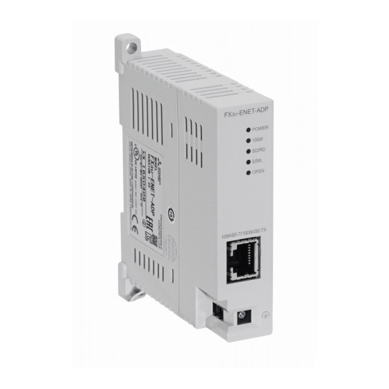
Page 23: Power And Status Leds
1 Introduction -ENET-ADP User's Manual 1.4 Power and Status LEDs Power and Status LEDs Status Description display Color Power is on POWER Green Power is off 100Mbps communication 100M Green 10Mbps communication or not connected Data being sent or received. SD/RD Green Data is not sent or received. -
Page 24: Specification
2 Specification -ENET-ADP User's Manual Specification DESIGN PRECAUTIONS • Make sure to include the following safety circuits outside the PLC to ensure safe system operation even during external power supply problems or PLC failure. Otherwise, malfunctions may cause serious accidents. 1) Above all, the following components should be included: an emergency stop circuit, a protection circuit, an interlock circuit for opposite movements (such as normal vs. -
Page 25: General Specifications
2 Specification -ENET-ADP User's Manual 2.1 General Specifications General Specifications For items not listed below, specifications are the same as those of the PLC main unit. For general specifications, refer to the manual of the PLC main unit. → Refer to FX Hardware Edition. -
Page 26: Performance Specification
2 Specification -ENET-ADP User's Manual 2.4 Performance Specification Performance Specification Item Specification MELSOFT connections Communication Using MC Protocol MELSOFT Direct Connection (Simple Connection) Functions Find CPU function Time setting function Diagnostics function from MELSOFT Number of simultaneously open connections MELSOFT connection + MC protocol <= 4 allowed Number of connectable units to the main unit 1 unit The time setting function (SNTP client) is enabled only after the trigger condition is established. -
Page 27: System Configuration
3 System Configuration -ENET-ADP User's Manual 3.1 General Configuration System Configuration This section explains the system configurations that may be used with the Ethernet adapter. General Configuration MELSOFT connection SNTP server Connection of user application and other company device (MC protocol) External device (Client) Maintenance... -
Page 28: Devices Required For Network Configuration
3 System Configuration -ENET-ADP User's Manual 3.2 Devices Required for Network Configuration Devices Required for Network Configuration This section explains the devices that are required to configure a network. Network installation work requires sufficient safeguards; ask a network specialist for installation. When connecting the Ethernet adapter to a network, either 10BASE-T or 100BASE-TX can be used. -
Page 29: Connection With Plc
3 System Configuration -ENET-ADP User's Manual 3.4 Connection with PLC Connection with PLC The Ethernet adapter connects to a FX PLC via a special adapter connector. Only one Ethernet adapter can be connected to the FX PLC. An expansion board is required to connect the Ethernet adapter with the FX -32MT-LT(-2) PLCs. - Page 30 3 System Configuration -ENET-ADP User's Manual 3.5 Assignment of channels • When using other communication expansion board/communication special adapter (CH2) (CH1) Communication Analog , FX -32MT-LT(-2) -ENET-ADP expansion special adapter Main unit board Caution on using the Ethernet adapter The Ethernet adapter is a communication special adapter, and occupies 1 communication channel. When the Ethernet adapter is used, only one other communication expansion board/communication special adapter (including the FX -8AV-BD and FX...
-
Page 31: Installation
4 Installation -ENET-ADP User's Manual Installation INSTALLATION PRECAUTIONS • Make sure to cut off all phases of the power supply externally before attempting installation work. Failure to do so may cause electric shock. INSTALLATION PRECAUTIONS • Use the product within the generic environment specifications described in PLC main unit manual (Hardware Edition). Never use the product in areas with excessive dust, oily smoke, conductive dusts, corrosive gas (salt air, Cl S, SO , or NO... -
Page 32: Fx 3U -Enet-Adp Connection
4 Installation -ENET-ADP User's Manual 4.1 FX3U-ENET-ADP Connection -ENET-ADP Connection An expansion board should be installed before connecting the Ethernet adapter. An expansion board is not required when the Ethernet adapter is connected to a FX (D, DS, DSS) PLC. -
Page 33: Din Rail Mounting
4 Installation -ENET-ADP User's Manual 4.2 DIN rail mounting DIN rail mounting The Ethernet adapter may be mounted on a 35mm (1.38") wide DIN46277 (DIN rail). Connect the Ethernet adapter to the PLC main unit before attaching the Ethernet adapter to a DIN rail. This section explains an example where the Ethernet adapter is connected to a FX PLC. -
Page 34: Direct Mounting
4 Installation -ENET-ADP User's Manual 4.3 Direct mounting Direct mounting When the Ethernet adapter is connected to a FX PLC, the Ethernet adapter may be mounted directly on a panel surface using screws. The direct mounting method is not available when the Ethernet adapter is connected to a FX PLC. -
Page 35: Wiring
5 Wiring -ENET-ADP User's Manual 5.1 Grounding Wiring WIRING PRECAUTIONS • Make sure to cut off all phases of the power supply externally before attempting wiring work. Failure to do so may cause electric shock or damage to the product. WIRING PRECAUTIONS •... -
Page 36: Screw Size And Tightening Torque
5 Wiring -ENET-ADP User's Manual 5.2 Screw Size and Tightening Torque Grounding wiring Example usage of FX D Grounding (100Ω or less) Ethernet modular jack (RJ45) -ENET-ADP Applicable cables Electric wire size 0.5 to 1.5 mm (AWG 20 to 16) •... -
Page 37: Connecting To The Network
5 Wiring -ENET-ADP User's Manual 5.3 Connecting to the Network Connecting to the Network The following explains how to connect the Ethernet adapter to 10BASE-T/100BASE-TX networks. Pay close attention to safety and use the Ethernet adapter properly. 1) Sufficient network knowledge and safety precautions are required when installing 10BASE-T or 100BASE-TX networks. -
Page 38: Introduction Of Functions
6 Introduction of Functions -ENET-ADP User's Manual 6.1 Functions List Introduction of Functions Functions List This section shows a list of Ethernet adapter functions. Functions Description Reference section This function allows communication with a MELSOFT product (such as GX Work2) MELSOFT connections Subsection 6.2.1 on a LAN (such as company LAN). -
Page 39: Melsoft Direct Connection (Simple Connection)
6 Introduction of Functions -ENET-ADP User's Manual 6.2 Details of functions 6.2.3 MELSOFT Direct Connection (Simple Connection) This function connects the Ethernet adapter attached to the main unit to a MELSOFT product (such as GX Works2) with one Ethernet cable without using the hub. The direct connection enables communication by only specifying the connection target. -
Page 40: Time Setting Function
6 Introduction of Functions -ENET-ADP User's Manual 6.2 Details of functions 6.2.5 Time setting function The Ethernet adapter collects time information from a time information server connected to LAN (SNTP server), making it possible to set the PLC main unit time automatically. The time setting function queries the time information server to ask the time at the specified timing. - Page 41 6 Introduction of Functions -ENET-ADP User's Manual 6.2 Details of functions Caution • Do not turn ON M8015 (Clock stop and clock setting) in the PLC main unit while the time setting function is used. Turning ON M8015 may cause errors in the Ethernet adapter. •...
-
Page 42: Parameter Setting Function
6 Introduction of Functions -ENET-ADP User's Manual 6.2 Details of functions 6.2.6 Parameter setting function This function sets parameters of the Ethernet adapter from GX Works2 via the PLC main unit. For details of operation setting, refer to Section 6.6. For details of open setting, refer to Section 6.11. For operation of GX Works2, refer to Section 8.1 and Section 8.2. -
Page 43: Setting Items List
6 Introduction of Functions -ENET-ADP User's Manual 6.3 Setting Items List Setting Items List The table below shows parameter settings set in the Ethernet adapter. Necessity of parameter setting Reference Setting Description section MC protocol MELSOFT Select whether or not the Ethernet adapter is connected. Channel When the Ethernet adapter is connected, select the channel Section 8.1... -
Page 44: Ethernet Adapter Setting
6 Introduction of Functions -ENET-ADP User's Manual 6.5 Ethernet adapter Setting Caution • When the parameter setting is added or changed in GX Works2, the contents of addition or change are not reflected automatically. After writing parameters of the Ethernet adapter, turn OFF the power of the Ethernet adapter (PLC), and turn it ON again. -
Page 45: Operational Settings
6 Introduction of Functions -ENET-ADP User's Manual 6.6 Operational Settings Operational Settings For operation of GX Works2, refer to Section 8.1. List of operation setting Setting Description IP address Set the Ethernet adapter IP address. Subnet mask Set the subnet mask pattern. pattern Default router IP Set the default router IP address. -
Page 46: Overview Of The Communication Procedure
6 Introduction of Functions -ENET-ADP User's Manual 6.7 Overview of the Communication Procedure 4) Communication data code settings Select the format of the communication data (MC Protocol) when communicating with an external device. Name of setting Description of setting Binary code Communicate using binary code data. -
Page 47: Initial Processing
6 Introduction of Functions -ENET-ADP User's Manual 6.8 Initial Processing Initial Processing This section explains the initial processing of the Ethernet adapter. 6.8.1 Initial processing Initial processing enables data communication with an external device by setting the parameters required for data communication via the Ethernet adapter. -
Page 48: Ping Command (Personal Computer -> Ethernet Adapter)
6 Introduction of Functions -ENET-ADP User's Manual 6.10 Confirming Completion of Initial Processing 6.10.1 PING command (Personal computer -> Ethernet adapter) For PING command operation of GX Works2, refer to Subsection 8.6.7. The following example illustrates how to confirm completion of initial processing by issuing the PING command to the local station's Ethernet adapter from an external device (personal computer) connected on the same Ethernet network. -
Page 49: Loop Back Test (Communication Using Mc Protocol)
6 Introduction of Functions -ENET-ADP User's Manual 6.11 Open Settings 6.10.2 Loop back test (Communication using MC protocol) The loop back test can be performed with communication using MC protocol in order to check the completion status of initial processing for the target Ethernet adapter. The following is an overview of the loop back test for communication using MC protocol. -
Page 50: Open Processing/Close Processing Of The Connection
6 Introduction of Functions -ENET-ADP User's Manual 6.12 Open Processing/Close Processing of the Connection 1) Protocol Select the protocol (communication method) for each connection between "TCP" and "UDP" in accordance with the external device. Select "TCP" when placing importance on the reliability of communication. Name of setting Description of setting Communicate using TCP/IP. - Page 51 6 Introduction of Functions -ENET-ADP User's Manual 6.12 Open Processing/Close Processing of the Connection 2) Close processing The purpose of close processing is to disconnect (cancel) the connection with the external device established by open processing mentioned previously. Close processing is used when terminating a connection with an external device, changing an external device of a connection, changing communication conditions, etc.
- Page 52 6 Introduction of Functions -ENET-ADP User's Manual 6.12 Open Processing/Close Processing of the Connection MEMO...
-
Page 53: Communication Using Mc Protocol
7 Communication Using MC Protocol -ENET-ADP User's Manual 7.1 Data Codes for Communication Communication Using MC Protocol This chapter gives an overview of the MC protocol. The frame type of MC protocol (data communication messages) used by the external device to access the PLC via this product is equivalent to A compatible 1E frame. -
Page 54: Accessing The Plc Using Mc Protocol
7 Communication Using MC Protocol -ENET-ADP User's Manual 7.2 Data Communication Function 7.2.1 Accessing the PLC using MC protocol This section explains the main functions for accessing the PLC using MC protocol. On the PLC side, the Ethernet adapter sends and receives data based on instructions (protocol) from external devices, so the PLC side does not require sequence programs for data communication. -
Page 55: Access Timing On The Plc Side
7 Communication Using MC Protocol -ENET-ADP User's Manual 7.2 Data Communication Function 7.2.3 Access Timing on the PLC Side The following diagram illustrates the access timing on the PLC side when an external device accesses the PLC via the Ethernet adapter. External device Read/write command Reply to the command... -
Page 56: Precautions On Data Communication
7 Communication Using MC Protocol -ENET-ADP User's Manual 7.3 Message Formats and Control Procedures 7.2.5 Precautions on Data Communication This section explains some precautions that should be observed when performing data communication between an external device and the Ethernet adapter. •... -
Page 57: Message Format And Control Procedure
7 Communication Using MC Protocol -ENET-ADP User's Manual 7.3 Message Formats and Control Procedures 2) When an external device writes data to the PLC (Command message) External Area C device side PLC side (Response message) a) Area C indicates transmission from the external device to the PLC. b) The program of the external device is generated so that the data is transmitted sequentially from left to right. - Page 58 7 Communication Using MC Protocol -ENET-ADP User's Manual 7.3 Message Formats and Control Procedures When communicating using the MC protocol, the user does not need to specify a response for a command from an external device; the Ethernet adapter generates it and then responds. 2) Control procedure The following diagrams illustrate the control procedure for communicating with the MC protocol and the order of data items in the application data field.
- Page 59 7 Communication Using MC Protocol -ENET-ADP User's Manual 7.3 Message Formats and Control Procedures b) Communication in binary code - When reading data from the local station PLC at the external device side External device side PLC side (Command message) Text (Command) (Data name) The contents and arrangement of the data items in...
-
Page 60: Contents Of Data Designation Items
7 Communication Using MC Protocol -ENET-ADP User's Manual 7.3 Message Formats and Control Procedures 7.3.3 Contents of data designation items This section explains the data items of commands and responses when communicating using MC protocol. In the response that is returned by the Ethernet adapter to an external device, the data is automatically specified by the Ethernet adapter;... - Page 61 7 Communication Using MC Protocol -ENET-ADP User's Manual 7.3 Message Formats and Control Procedures 7) Complete code The result of processing when an external device reads/writes data from/to the target PLC station is indicated by the following values. 00H : Normal completion Other than 00H :Abnormal completion (50 to 60H) a) When communicating in binary code, the complete code is expressed in binary values.
- Page 62 7 Communication Using MC Protocol -ENET-ADP User's Manual 7.3 Message Formats and Control Procedures <Note> The following example shows the designation of the subheader to the monitoring timer when communicating using MC protocol under the following conditions. (Designated value) • Target station : series to which Ethernet adapter is connected : FFH •...
- Page 63 7 Communication Using MC Protocol -ENET-ADP User's Manual 7.3 Message Formats and Control Procedures 2) Format when communicating in ASCII code a) The order when sending a command (external device Ethernet adapter) Application data Subheader PC number Monitoring timer Header "0"...
-
Page 64: Character Area Transmission Data
7 Communication Using MC Protocol -ENET-ADP User's Manual 7.3 Message Formats and Control Procedures 7.3.4 Character area transmission data This section explains how to transmit the bit device data and word device data handled in the character areas, as well as the order of transmission when communicating data between an external device and the PLC by each command. - Page 65 7 Communication Using MC Protocol -ENET-ADP User's Manual 7.3 Message Formats and Control Procedures b) When reading from or writing to a word device memory Each word of the word device memory is expressed in hexadecimal values in 4-bit units sequentially from the higher bit.
- Page 66 7 Communication Using MC Protocol -ENET-ADP User's Manual 7.3 Message Formats and Control Procedures 2) Data communication using binary code a) When reading from or writing to a bit device memory The bit device memory can be read and written in bit units (one device point) or word units (16 device points).
- Page 67 7 Communication Using MC Protocol -ENET-ADP User's Manual 7.3 Message Formats and Control Procedures b) Reading from or writing to a word device memory Each word of a word device memory is designated by 16 bits and the designated number of points from the designated head device are sequentially expressed in one-point units in the order, low byte (L: bits 0 to 7) to high byte (H: bits 8 to 15).
-
Page 68: List Of Commands And Functions For The Mc Protocol
7 Communication Using MC Protocol -ENET-ADP User's Manual 7.4 List of Commands and Functions for The MC protocol List of Commands and Functions for The MC protocol The following table lists the commands and functions when an external device accesses the PLC. Number of points Command/ Function... - Page 69 7 Communication Using MC Protocol -ENET-ADP User's Manual 7.4 List of Commands and Functions for The MC protocol MEMO...
-
Page 70: Device Memory Read/Write
7 Communication Using MC Protocol -ENET-ADP User's Manual 7.5 Device Memory Read/Write Device Memory Read/Write This section explains the designations in the control procedure when reading from and writing to device memory by providing an example. 7.5.1 Commands and device range 1) Commands used for reading from and writing to device memory Number of points Command/... - Page 71 7 Communication Using MC Protocol -ENET-ADP User's Manual 7.5 Device Memory Read/Write b) The following table outlines the device codes and numbers. Device Device code Device range Device number D0 to D7999 0000 to 1F3FH Data register (44H, 20H) D8000 to D8511 1F40 to 213FH Extension register R0 to R32767...
-
Page 72: Batch Read In Bit Units (Command: 00)
7 Communication Using MC Protocol -ENET-ADP User's Manual 7.5 Device Memory Read/Write 7.5.2 Batch read in bit units (command: 00) The examples shown in this section explain the command/response format when batch-reading bit device memory. For more details on the order and content of data items of the areas marked by " * " shown in the control procedure diagram, refer to Subsection 7.3.2. - Page 73 7 Communication Using MC Protocol -ENET-ADP User's Manual 7.5 Device Memory Read/Write 2) Communication in ASCII code (Data name) Head device External device side H L H - - - - L H L (Example) Data for the number (Data name) of designed device points PLC side...
-
Page 74: Batch Write In Bit Units (Command: 02)
7 Communication Using MC Protocol -ENET-ADP User's Manual 7.5 Device Memory Read/Write 7.5.3 Batch write in bit units (command: 02) The examples shown in this section explain the command/response format when batch writing to bit device memory. For more details on the order and content of data items of the areas marked by " * " shown in the control procedure diagram, refer to Subsection 7.3.2. - Page 75 7 Communication Using MC Protocol -ENET-ADP User's Manual 7.5 Device Memory Read/Write 2) Communication in ASCII code Data for the number (Data name) of designed device points Monitoring Head device timer Characters for the External device number of device points side H L H (Example)
-
Page 76: Test In Bit Units (Random Write) (Command: 04)
7 Communication Using MC Protocol -ENET-ADP User's Manual 7.5 Device Memory Read/Write 7.5.4 Test in bit units (random write) (command: 04) The examples shown in this section explain the command/response format when writing data by designating bit device memories arbitrarily. For more details on the order and content of data items of the areas marked by "... - Page 77 7 Communication Using MC Protocol -ENET-ADP User's Manual 7.5 Device Memory Read/Write 2) Communication in ASCII code (Data name) External device Designated device Designated device side (Example) ON Y45 OFF M60 45 (Octadecimal) = 25 (Hexadecimal) Designated device (Data name) ON S38 PLC side (Example)
-
Page 78: Batch Read In Word Units (Command: 01)
7 Communication Using MC Protocol -ENET-ADP User's Manual 7.5 Device Memory Read/Write 7.5.5 Batch read in word units (command: 01) The examples shown in this section explain the command/response format when batch reading word device memory or bit device memory (16 point units). For more details on the order and content of data items of the areas marked by "... - Page 79 7 Communication Using MC Protocol -ENET-ADP User's Manual 7.5 Device Memory Read/Write 2) Communication in ASCII code (Data name) External device Head device side (Example) 0 0 A 5 Y100 Data for the number (Data name) of designed device 32/16 = 2 points points Characters for the PLC side...
- Page 80 7 Communication Using MC Protocol -ENET-ADP User's Manual 7.5 Device Memory Read/Write <Note> C200 to C255 (Current Values) Batch Read Since C200 to C255 are 32 bit devices, the device points should be specified with twice as many points as are actually read.
- Page 81 7 Communication Using MC Protocol -ENET-ADP User's Manual 7.5 Device Memory Read/Write 2) Communication in ASCII code (Data name) Monitoring Head device timer External device side 4 3 4 E 0 0 0 0 0 0 D C 4 0 0 0 (Example) (4 bytes x 2) x 32=256bytes Head data...
-
Page 82: Batch Write In Word Units (Command: 03)
7 Communication Using MC Protocol -ENET-ADP User's Manual 7.5 Device Memory Read/Write 7.5.6 Batch write in word units (command: 03) The examples shown in this section explain the command/response format when batch writing to word device memory or bit device memory (16 point units). For more details on the order and content of data items of the areas marked by "... - Page 83 7 Communication Using MC Protocol -ENET-ADP User's Manual 7.5 Device Memory Read/Write 2) Communication in ASCII code Data for the number of (Data name) designed device points Head device External device (Characters for the number of device points) side H L H L H L (Example) D100...
- Page 84 7 Communication Using MC Protocol -ENET-ADP User's Manual 7.5 Device Memory Read/Write <Note> C200 to C255 (Current Values) Batch Write Since C200 to C255 are 32 bit devices, the device points should be specified with twice as many points as are actually written.
- Page 85 7 Communication Using MC Protocol -ENET-ADP User's Manual 7.5 Device Memory Read/Write 2) Communication in ASCII code (Data name) Monitoring Head device timer External device side 4 3 4 E 0 0 0 0 0 0 D C (Example) 32 points x 2 = 64word (4 bytes x 2) x 32 = 256 bytes Head data Last data...
-
Page 86: Test In Word Units (Random Write) (Command: 05)
7 Communication Using MC Protocol -ENET-ADP User's Manual 7.5 Device Memory Read/Write 7.5.7 Test in word units (random write) (command: 05) The examples shown in this section explain the command/response format when writing data by designating word device memories or bit device memories (16 point units) arbitrarily. These examples are not applicable for writing the current values of C200 to C255 (32-bit devices). - Page 87 7 Communication Using MC Protocol -ENET-ADP User's Manual 7.5 Device Memory Read/Write 2) Communication in ASCII code (Data name) Designated device Device data Designated device Device data Monitoring (ON/OFF External device timer designation) side H L H - - L H - - H - - L H - - H - - L...
-
Page 88: Remote Run/Stop, Plc Model Name Code Read
7 Communication Using MC Protocol -ENET-ADP User's Manual 7.6 Remote RUN/STOP, PLC model name code read Remote RUN/STOP, PLC model name code read This function is used to remotely RUN/STOP a PLC and read the model name of a PLC from an external device. -
Page 89: Remote Run (Command: 13H)/Remote Stop (Command: 14H)
7 Communication Using MC Protocol -ENET-ADP User's Manual 7.6 Remote RUN/STOP, PLC model name code read 7.6.2 Remote RUN (command: 13H)/Remote STOP (Command: 14H) The examples shown in this section explain the control procedure of remote RUN. The order and content of data items of the areas marked by " * " shown in the control procedure diagram differ depending on the module used as well as the frame and format used for communication. -
Page 90: Plc Model Name Read (Command: 15H)
7 Communication Using MC Protocol -ENET-ADP User's Manual 7.6 Remote RUN/STOP, PLC model name code read 7.6.3 PLC model name read (command: 15H) The examples shown in this section explain the control procedure for reading the model name of the PLC. The order and content of data items of the areas marked by "... - Page 91 7 Communication Using MC Protocol -ENET-ADP User's Manual 7.6 Remote RUN/STOP, PLC model name code read MEMO...
-
Page 92: Loopback Test
7 Communication Using MC Protocol -ENET-ADP User's Manual 7.7 Loopback Test Loopback Test A loopback test checks whether or not the communication function between an external device and the Ethernet adapter operates normally. The examples show the control procedure using this function. Caution •... - Page 93 7 Communication Using MC Protocol -ENET-ADP User's Manual 7.7 Loopback Test 2) Performing a loopback test while communicating in ASCII code (Designated byte length 2)+10bytes (Data name) External device side (Example) (Data name) PLC side (Example) (Designated byte length 2)+6bytes Caution The loopback data transmitted by an external device is returned to the external device as is.
-
Page 94: The Operation Of Gx Works2
8 The Operation of GX Works2 -ENET-ADP User's Manual 8.1 Ethernet adapter Setting The Operation of GX Works2 This chapter explains operations of GX Works 2 related to the Ethernet adapter setting and others. GX Works2 Ver. 1.73B and later supports the Ethernet adapter setting. In order to set up the Ethernet adapter by GX Works2, FX Configurator-EN needs to be installed. - Page 95 8 The Operation of GX Works2 -ENET-ADP User's Manual 8.1 Ethernet adapter Setting Setting Description Specify the subnet mask pattern. [Setting range] Subnet Mask Pattern • 192.0.0.0 to 255.255.255.252 (Decimal) • C0.00.00.00 to FF.FF.FF.FC (Hexadecimal) Specify the IP address of the default router when it is used. [Setting range] Default Router IP Address •...
-
Page 96: Open Setting
8 The Operation of GX Works2 -ENET-ADP User's Manual 8.2 Open Setting Open Setting On the "Ethernet Adapter Open Setting" screen, set the protocol, open system and others. Up to four connections can be set up. MELSOFT connection + MC protocol <= 4 connection Click the [Open Setting] button on the "Ethernet Adapter"... -
Page 97: Melsoft Connections
8 The Operation of GX Works2 -ENET-ADP User's Manual 8.2 Open Setting 8.2.1 MELSOFT connections MELSOFT connection can be set by selecting "TCP" in the "Protocol" column and selecting "MELSOFT Connection" in the "Open System" column for the used connection No. on the "Ethernet Adapter Open Setting"... -
Page 98: Time Setting
8 The Operation of GX Works2 -ENET-ADP User's Manual 8.3 Time Setting Time Setting On the "Time Setting" screen, set the SNTP server IP address and others. Click the [Time Setting] button on the "Ethernet Adapter" screen to display the screen below. Setting Description SNTP Function Setting... -
Page 99: Log Record Setting
8 The Operation of GX Works2 -ENET-ADP User's Manual 8.4 Log Record Setting Log Record Setting On the "Log Record Setting" screen, set the error log save destination and others. The user device (D, R) is used to save the error log, etc. Click the [Log Record Setting] button on the "Ethernet Adapter"... -
Page 100: Online Function
8 The Operation of GX Works2 -ENET-ADP User's Manual 8.5 Online Function Online Function 8.5.1 Designation of destination to be connected When the FX PLC is connected using the Ethernet adapter, the following route is used. Personal Other Station computer PLC side I/F Setting Connection pathname / Imaged figure / Explanation... - Page 101 8 The Operation of GX Works2 -ENET-ADP User's Manual 8.5 Online Function 1) Transfer Setup screen When connecting the FX PLC using the Ethernet adapter, set the following contents on the "Transfer Setup Connection" screen. a) PC side I/F "Ethernet Board" is chosen. b) PLC side I/F Double-click "PLC Module"...
- Page 102 8 The Operation of GX Works2 -ENET-ADP User's Manual 8.5 Online Function 2) PLC side I/F Detailed Setting of PLC Module screen On the "PLC side I/F Detailed Setting of PLC Module" screen, set the connection type (direct connection to the Ethernet port or connection via a hub) and others. For connection via a hub, the method to directly enter the IP address and host name and the method to search for connected PLC units and select one from the list are available.
-
Page 103: Find Cpu Function
8 The Operation of GX Works2 -ENET-ADP User's Manual 8.5 Online Function Setting Description This list shows the result of searching for FX PLC main units connected on the network. • IP address : Displays the IP address of a found PLC (in decimal). •... - Page 104 8 The Operation of GX Works2 -ENET-ADP User's Manual 8.5 Online Function GX Works2 searches for FXCPU units, and displays the list of found FXCPU units. Check the item "Do not respond to search for CPU on network" to give no response to the search for CPU units on the network.
-
Page 105: Ethernet Diagnostics
8 The Operation of GX Works2 -ENET-ADP User's Manual 8.6 Ethernet Diagnostics Ethernet Diagnostics The Ethernet diagnostics function checks various setting status in the Ethernet adapter. • Ethernet diagnostics function outline When the Ethernet adapter is used, the Ethernet diagnostics function monitors and tests the following items. - Page 106 8 The Operation of GX Works2 -ENET-ADP User's Manual 8.6 Ethernet Diagnostics Ethernet diagnostics screen is displayed from the "Diagnostics" "Ethernet Diagnostics" menu. Ethernet diagnostics screen Item Description Ethernet Diagnostics (FX Ethernet Adapter) [CH*] [Title bar] "[CH*]" indicates the channel being diagnosed (* = 1 or 2). Change IP Address Display Select the IP address notation on various tab screens between decimal and hexadecimal.
-
Page 107: Parameter Status
8 The Operation of GX Works2 -ENET-ADP User's Manual 8.6 Ethernet Diagnostics 8.6.1 Parameter status Parameter status is monitored. Item Description IP Address IP address is displayed. Subnet Mask Pattern Subnet mask pattern is displayed. Default Router IP Address Default router IP address is displayed. Ethernet address is displayed. -
Page 108: Error History
8 The Operation of GX Works2 -ENET-ADP User's Manual 8.6 Ethernet Diagnostics 8.6.2 Error history Error history is monitored. • When "Set error log save destination" (area) in the PLC parameters is set to save ten records, only 10 lines become valid. -
Page 109: Status Of Each Connection, Access History
8 The Operation of GX Works2 -ENET-ADP User's Manual 8.6 Ethernet Diagnostics 8.6.3 Status of each connection, Access History Status of each connection and access history is monitored. Item and description of status of each connection. Item Description Connection No./Function Connection No. - Page 110 8 The Operation of GX Works2 -ENET-ADP User's Manual 8.6 Ethernet Diagnostics Item and description of access history. Item Description Year/Month/Day Date when the error occurred is displayed. Time Time when the error occurred is displayed. Connection No. Connection No. (1 to 4) is displayed. Protocol Protocol is displayed.
-
Page 111: Status Of Each Protocol
8 The Operation of GX Works2 -ENET-ADP User's Manual 8.6 Ethernet Diagnostics 8.6.4 Status of each protocol Number of communication packets is monitored. Item Description Total Number of Receives Total number of TCP packets received is displayed. TCP Packet Total Number of Sends Total number of TCP packets sent is displayed. -
Page 112: Connection Status
8 The Operation of GX Works2 -ENET-ADP User's Manual 8.6 Ethernet Diagnostics 8.6.5 Connection Status Connection status (communicating status) is monitored. Item Description Full Duplex/Half Duplex Full Duplex or Half Duplex is displayed. Connection Status Connecting or Disconnected is displayed. 10BASE-T/100BASE-TX 10BASE-T or 100BASE-TX is displayed. -
Page 113: Time Setting Status
8 The Operation of GX Works2 -ENET-ADP User's Manual 8.6 Ethernet Diagnostics 8.6.6 Time setting status Time setting status is monitored. Item Description Latest Time Setting Displays the result Succeeded/Failed/Not Executed with respect to the latest time setting. Execution Time Execution time of time setting is displayed. -
Page 114: Ping Test
8 The Operation of GX Works2 -ENET-ADP User's Manual 8.6 Ethernet Diagnostics 8.6.7 PING test The PING test checks for the presence of Ethernet modules on the Ethernet network whose initial processing is completed, or the presence of specified IP address. Execute the PING test to the Ethernet adapter to confirm the following items. - Page 115 8 The Operation of GX Works2 -ENET-ADP User's Manual 8.6 Ethernet Diagnostics Item and description of the PING test screen Item Description IP Address Set PING test target station IP address. Address IP Address Input Format Input format of the IP address and decimal/hexadecimal are chosen. Specification IP Address/Host Name Set IP address or host name.
- Page 116 8 The Operation of GX Works2 -ENET-ADP User's Manual 8.6 Ethernet Diagnostics [Description details of the result column] 1) Display of the PING test a) Description of the IP address specification display Pinging [IP address] with [Set size] bytes of data: b) Example of IP address specification display Pinging 192.168.0.3 with 32 bytes of data: c) Description of the host name specification display...
-
Page 117: Print Function
8 The Operation of GX Works2 -ENET-ADP User's Manual 8.7 Print Function Print Function This section explains the print content of each setting in the Ethernet adapter. Caution Printing Ethernet adapter information cannot be executed when "Channel" is set to "None" in the Ethernet adapter setting. - Page 118 8 The Operation of GX Works2 -ENET-ADP User's Manual 8.7 Print Function Example of print preview image of the "Ethernet Adapter" Example of print preview image of the "Ethernet Adapter Open Setting" Example of print preview image of the "Ethernet Adapter Time Setting" (when the execution time is valid)
- Page 119 8 The Operation of GX Works2 -ENET-ADP User's Manual 8.7 Print Function Example of print preview image of the "Ethernet Adapter Time Setting" (when the execution interval is valid) Example of print preview image of the "Ethernet Adapter Log Record Setting"...
-
Page 120: Printing Of The Display Screen
8 The Operation of GX Works2 -ENET-ADP User's Manual 8.7 Print Function 8.7.2 Printing of the display screen Click the [Print Window] button on the "Ethernet Adapter" tab of "FX Parameter" screen to print the display window. Example of print preview image of the "Ethernet Adapter" Example of print preview image of the "Ethernet Adapter Open Setting"... - Page 121 8 The Operation of GX Works2 -ENET-ADP User's Manual 8.7 Print Function Example of print preview image of the "Ethernet Adapter Time Setting" (when the execution interval is valid) Example of print preview image of the "Ethernet Adapter Log Record Setting"...
-
Page 122: Troubleshooting
POWER the power of the PLC When the connection is all right, the hardware may be defective. main unit is turned ON. For repair, contact your local Mitsubishi Electric representative. 1) Using 10Mbps HUB • Initial processing. • Replace with 100Mbps HUB. -
Page 123: How To Turn Off Err. Led And To Read/Clear Error Information
PLC (Ethernet 2) Ethernet adapter error (H/W error) adapter). For repair, contact your local Mitsubishi Electric representative. 1) Check the contents of the error using the error codes stored by the error detection of the ERR. following and remove the causes. -
Page 124: How To Check An Error Through Gx Works2
9 Troubleshooting -ENET-ADP User's Manual 9.2 How to Check an Error Through GX Works2 How to Check an Error Through GX Works2 Use the Ethernet diagnostics function of GX Works2 to check the Ethernet adapter status, parameter setting, communication status and error history. 9.2.1 Ethernet diagnostics For Ethernet diagnostics of GX Works2, refer to Section 8.6. -
Page 125: Error Code List
9 Troubleshooting -ENET-ADP User's Manual 9.3 Error Code List Error Code List 9.3.1 Error code of Ethernet communication This section explains the error codes (abnormal codes) for errors that may occur in each processing when communicating between the Ethernet adapter and an external device as well as those generated by processing requests from the local station's FX series PLC. - Page 126 9 Troubleshooting -ENET-ADP User's Manual 9.3 Error Code List Error ERR. Description Corrective action Code (decimal) The Ethernet adapter IP address and default router IP address do not belong Correct the IP address. Set the class to "A", "B" to the same network address when the default router IP address is specified. or "C".
- Page 127 9 Troubleshooting -ENET-ADP User's Manual 9.3 Error Code List Error ERR. Code Description Corrective action (decimal) • Check operation of the external device. • The line may be jammed with packets. Wait A receive error occurred in UDP/IP communication. for a while, and execute sending again. •...
- Page 128 9 Troubleshooting -ENET-ADP User's Manual 9.3 Error Code List Error ERR. Description Corrective action Code (decimal) 10166 10167 10168 10169 10853 12650 20154 20155 20156 20159 20353 20354 20356 20357 20359 20360 • Check the connection status of connectors. 20361 •...
-
Page 129: End Codes (Completion Codes) Returned To An External Device During Data Communication
9 Troubleshooting -ENET-ADP User's Manual 9.3 Error Code List 9.3.2 End codes (completion codes) returned to an external device during data communication This section explains the end codes (completion codes) that are added to responses when communicating using the MC protocol. For more details on the error codes that are added to responses during communication using A compatible 1E frames through the MC protocol, refer to Subsection 9.3.3. -
Page 130: Abnormal Codes Returned During Communication Using Mc Protocol
9 Troubleshooting -ENET-ADP User's Manual 9.3 Error Code List 9.3.3 Abnormal codes returned during communication using MC protocol This section explains the abnormal codes (error codes) that are added to responses when communicating using MC protocol (An abnormal code is added only when an end code is "5B".) For more details on the end codes (error codes) that are added to responses, refer to Subsection 9.3.2. -
Page 131: Troubleshooting Flowchart
9 Troubleshooting -ENET-ADP User's Manual 9.4 Troubleshooting Flowchart Troubleshooting Flowchart This section explains some simple troubleshooting procedures when the Ethernet adapter and an external device have communication problems in a flowchart format. <POINT> If trouble occurs when using the Ethernet adapter, check the block status, error status and others for the Ethernet adapter using the Ethernet diagnostic function of GX Works2 described in Section 8.6 and Subsection 9.2.1. - Page 132 9 Troubleshooting -ENET-ADP User's Manual 9.4 Troubleshooting Flowchart If [ERR.] LED turns ON, refer to Section 9.1. When an error is shown in the Error history (refer to Subsection 8.6.2) offered by the Ethernet diagnostics function of GX Works2, check the error code, and check the contents of the error and take countermeasures in accordance with Subsection 9.3.1.
-
Page 133: Errors In Communication Using Mc Protocol
9 Troubleshooting -ENET-ADP User's Manual 9.4 Troubleshooting Flowchart 9.4.1 Errors in communication using MC protocol Communication error Check the open status of the connection with the external device. Perform open setting. [OPEN] LED lit? (For details, refer to Section 6.11 and Section 9.2.) Was a command sent Send the command to the Ethernet... - Page 134 9 Troubleshooting -ENET-ADP User's Manual 9.4 Troubleshooting Flowchart Is the IP address of the Correct the IP address and send the command correct? command again. Are the command formats, such as command type, device Correct the command format. designation, and address designation, designated correctly? Are there any open...
-
Page 135: Appendix A: List Of The Special Devices
Appendix A: List of the Special Devices -ENET-ADP User's Manual Appendix A: List of the Special Devices The Ethernet adapter uses the following special auxiliary relays and special data registers of the PLC main unit. The device number of used special auxiliary relays and special data registers varies depending on the connection channel in the Ethernet adapter. - Page 136 Appendix A: List of the Special Devices -ENET-ADP User's Manual Device number Name Description Stores the connection status of the Ethernet port in the Ethernet adapter. b10: Connection condition 0: The hub or external device is disconnected, or the cable is D8407 D8427 Connection condition of the Ethernet port defective (wire breakage).
-
Page 137: Appendix B: Version Information
Appendix B: Version Information -ENET-ADP User's Manual Appendix B-1 Version check method Appendix B: Version Information Appendix B-1 Version check method 1. Checking the nameplate The Ethernet adapter version is indicated by "VERSION" on the label attached to the left side of the module when viewed from the front. -
Page 138: Appendix C: Program Examples
Appendix C: Program Examples -ENET-ADP User's Manual Appendix C: Program Examples The program examples presented in this section test the connection between the Ethernet adapter and an external device (personal computer) that is connected to the same Ethernet. For each program, only the minimum programming that is required to perform the communication test is done. -
Page 139: Appendix C-1 Program Example For Communication Using Mc Protocol -1
Appendix C: Program Examples -ENET-ADP User's Manual Appendix C-1 Program example for communication using MC protocol -1 Appendix C-1 Program example for communication using MC protocol -1 The following explains a program example, its execution environment and the contents of data communication. - Page 140 Appendix C: Program Examples -ENET-ADP User's Manual Appendix C-1 Program example for communication using MC protocol -1 <Remarks> • The following explains an outline of the compiling procedure for a program created using Microsoft Corporation Visual C++ .NET 1) Start Visual C++ . 2) Prepare for program creation.
- Page 141 ** / main unit / ** Ethernet adapter. ** / / ** ** / / ** Copyright(C) 2011 Mitsubishi Electric Corporation ** / / ** All Rights Reserved ** / / ** ** / / ******************************************************************** / #include <stdio.h>...
- Page 142 // Connection completion flag off nErrorStatus=WSAStartup(wVersionRequested,&wsaData); // Winsock Initial processing if (nErrorStatus!=SOCK_OK) { Sockerror(ERROR_INITIAL); // Error handling return (SOCK_NG); printf ("Winsock Version is %ld.%ld\n",HIBYTE(wsaData.wVersion),LOBYTE(wsaData.wVersion)); printf ("FX3U-ENET-ADP Test Start\n"); socketno=socket(AF_INET,SOCK_STREAM,0); // Create socket for TCP/IP if (socketno==INVALID_SOCKET){ Sockerror (ERROR_SOCKET); // Error handling return(SOCK_NG); hostdata.sin_family=AF_INET;...
- Page 143 Appendix C: Program Examples -ENET-ADP User's Manual Appendix C-1 Program example for communication using MC protocol -1 if(length == SOCKET_ERROR) { nErrorStatus = WSAGetLastError(); if(nErrorStatus != WSAEWOULDBLOCK) { Sockerror(ERROR_RECIEVE); // Error handling return (SOCK_NG); } else { continue; // Repeat until messages are received } else { rbuf_idx += length;...
- Page 144 Appendix C: Program Examples -ENET-ADP User's Manual Appendix C-1 Program example for communication using MC protocol -1 if(shutdown(socketno,2)!=SOCK_OK){ // Processing to disable sending/receiving Sockerror(ERROR_SHUTDOWN); // Error handling return(SOCK_NG); if(closesocket(socketno)!=SOCK_OK){ // Close processing Sockerror(ERROR_CLOSE); // Error handling return(SOCK_NG); Closeflag=FLAG_OFF; // Connection completion flag off WSACleanup();...
-
Page 145: Appendix C-2 Program Example For Communication Using Mc Protocol -2
Appendix C: Program Examples -ENET-ADP User's Manual Appendix C-2 Program example for communication using MC protocol -2 Appendix C-2 Program example for communication using MC protocol -2 This section explains an example of an external device program that reads/writes data from/to the PLC. A sample program, its execution environment and contents of data communication are shown below. - Page 146 Appendix C: Program Examples -ENET-ADP User's Manual Appendix C-2 Program example for communication using MC protocol -2 5) Sample program (Form 1) Parts in italic are created automatically by Visual Basic .NET, so no input is required. Only input where written in bold. Option Explicit On Option Strict On Imports System.Net.Sockets...
- Page 147 Appendix C: Program Examples -ENET-ADP User's Manual Appendix C-2 Program example for communication using MC protocol -2 'lstOutput Me.lstOutput.ItemHeight = 12 Me.lstOutput.Location = New System.Drawing.Point(16, 64) Me.lstOutput.Name = "lstOutput" Me.lstOutput.Size = New System.Drawing.Size(264, 196) Me.lstOutput.TabIndex = 1 'Form1 Me.AutoScaleBaseSize = New System.Drawing.Size(5, 12) Me.ClientSize = New System.Drawing.Size(296, 273) Me.Controls.Add(Me.lstOutput) Me.Controls.Add(Me.Start)
- Page 148 Appendix C: Program Examples -ENET-ADP User's Manual Appendix C-2 Program example for communication using MC protocol -2 'Read D0 to D4 (5 points) with the A-compatible 1E frame command. TxCommand = "01ff000a4420000000000500" Buffer = System.Text.Encoding.Default.GetBytes(TxCommand.ToCharArray) 'Sending a read command Client.GetStream().Write(Buffer, 0, Buffer.Length) 'Waiting for a response from an Ethernet adapter While Not Client.GetStream().DataAvailable() Application.DoEvents()
-
Page 149: Appendix D: Differences With Fx 3U -Enet
Appendix D: Differences with FX3U-ENET -ENET-ADP User's Manual Appendix D: Differences with FX -ENET The table below shows major differences between the FX -ENET-ADP and the FX -ENET. : Supported : Not supported Item Summary -ENET-ADP -ENET Reading/writing data on the PLC main unit from/to Communication A-compatible 1E external devices (The frame method is compatible... - Page 150 Appendix D: Differences with FX3U-ENET -ENET-ADP User's Manual Item Summary -ENET-ADP -ENET Adapter connection (Only the adapter final Connection system Connection method to the PLC. bus connection stage (leftmost position) connectable) The left side of the main The right side of the main Mounting position Mounting position when connected to the PLC.
-
Page 151: Appendix E: Document, Others
Appendix E: Document, others -ENET-ADP User's Manual Appendix E-1 Setting Value Recording Sheets Appendix E: Document, others Appendix E-1 Setting Value Recording Sheets This section provides setting value recording sheets for parameters set with GX Works2. Make copies as needed. Setting value recording sheet No. - Page 152 Appendix E: Document, others -ENET-ADP User's Manual Appendix E-1 Setting Value Recording Sheets Recording sheet 2 [Adapter number Setting data GX Works2 Data item setting screen Check/Setting value Remark Not Set Protocol MELSOFT connection Open System MC protocol Connection No. Host Station Port No.
- Page 153 Appendix E: Document, others -ENET-ADP User's Manual Appendix E-1 Setting Value Recording Sheets Recording sheet 3 [Adapter number Setting data GX Works2 Data item setting screen Check/Setting value Remark SNTP Function Setting Not Used Adjust to input SNTP Server IP Address format Decimal IP address input...
- Page 154 Appendix E: Document, others -ENET-ADP User's Manual Appendix E-1 Setting Value Recording Sheets Recording sheet 4 [Adapter number Setting data GX Works2 Data item setting screen Check/Setting value Remark Checked/ Set error log save destination Unchecked Number of Records Error Head device type Device Head device number...
-
Page 155: Appendix E-2 Processing Time
Appendix E: Document, others -ENET-ADP User's Manual Appendix E-2 Processing Time Appendix E-2 Processing Time Calculate the minimum processing time for MC protocol using the expressions below. Note that the processing time may become longer depending on the load factor on the network (how congested the line is), the window size of each connected device, the number of connections used concurrently, and how the system is configured. -
Page 156: Appendix E-3 Ascii Code List
Appendix E: Document, others -ENET-ADP User's Manual Appendix E-3 ASCII Code List Appendix E-3 ASCII Code List 1. ASCII code table (7-bit code expressed in hexadecimal) Hexadecimal SOH DC1 STX DC2 ” ETX DC3 EOT DC4 ENQ NAK ACK SYN &... -
Page 157: Appendix E-4 References
Appendix E: Document, others -ENET-ADP User's Manual Appendix E-4 References Appendix E-4 References For details on TCP/IP, refer to the DDN Protocol Handbook (3 volumes). Publisher DDN Network Information Center SRI International 333 Ravenswood Avenue, EJ291 Menlo Park, California 94025 RFC Number TCP RFC793 UDP RFC768... - Page 158 Appendix E: Document, others -ENET-ADP User's Manual Appendix E-6 ICMP Protocol Supported by Ethernet adapter MEMO...
-
Page 159: Warranty
Warranty -ENET-ADP User's Manual Warranty Please confirm the following product warranty details before using this product. 1. Gratis Warranty Term and Gratis Warranty Range 2. Onerous repair term after discontinuation of production If any faults or defects (hereinafter "Failure") found to be the responsibility of Mitsubishi occurs during use of the Mitsubishi shall accept onerous product repairs for product within the gratis warranty term, the product shall be... -
Page 160: Revised History
Revised History -ENET-ADP User's Manual Revised History Date Revision Description 2/2012 First Edition... - Page 162 -ENET-ADP USER'S MANUAL HEAD OFFICE: TOKYO BUILDING, 2-7-3 MARUNOUCHI, CHIYODA-KU, TOKYO 100-8310, JAPAN HIMEJI WORKS: 840, CHIYODA CHO, HIMEJI, JAPAN FX3UENETADP-U-E MODEL 09R725 MODEL CODE JY997D45801A Effective Feb. 2012 (MEE) Specifications are subject to change without notice.