Steamist SM-12 Installation Instructions Manual
Steambath generator
Hide thumbs
Also See for SM-12:
- Electrical installation instructions (8 pages) ,
- Electrical installation instructions (4 pages)
Table of Contents
Advertisement
Electrical Installation Instructions
WARNING: Elderly persons, pregnant women, or those suffering from heart disease, high blood
!
pressure, diabetes, or who are otherwise not in good health, do not use this device unless
directed to do so by a physician. Also, do not use steambath while under the influence of alcohol.
IMPORTANT: the warranty of this product is voided if it is used in a commercial application or for anything other than a
residential steambath installation. All electrical connections must be performed by a licensed electrician in accordance
with Local and National Electric Codes.
The Steamist "SM" generator operates with one or two
controls appropriately located inside and/or outside the
steamroom. It's small enough in size to be tucked away
using very little space in a vanity, closet, basement, or an
insulated attic, but large enough to provide steam for most
residential baths.
The
Steamist
"SM"
factory-assembled carefully wired and tested.
NOTE: The TC-110, TC-135, DSC-425, and DSP
Controls are designed to work with all Steamist "SM"
Generators.
1. Pre-Installation
Proper electrical supply (208 or 240 Volt): See rating
a)
label on Steam Generator and Chart on back page.
Determine proper size of wire, voltage, amperage,
and phase for the Steam Generator. Only UL rated
90°C wire can be used.
b)
In-line fuse/circuit breaker required: Fuse/circuit
breaker to be installed must be sized in accordance
with chart on back page. Do NOT install a GFI
(Ground Fault Interrupter) to this equipment (per
article 210-8 in the National Electric Code).
c)
Route power supply cable to the location where the
Steam Generator will be installed (before walls are
closed).
2. Electrical Rough-In
a)
Route appropriate power cable to the location the
Steam Generator will be installed. If receptacle is
desired, mount the box for the receptacle near the
location of the Steam Generator (See Figure 3:
NOTE: The plug and receptacle require a rating of
no less than 250V and proper amperage. Refer to
chart on page 4 for amperage rating.
After the walls are complete, the Steam Generator
and Control can be wired.
07/07
Steambath
Generator
Steambath Generators
3. Steam Generator Electrical Installation
WARNING: All power to the steam generator must
be turned off.
a)
Remove the six screws holding the electrical access
cover and remove cover.
b)
Locate the supply line knockout. Mount proper
comes
strain relief into knockout hole.
c)
Strip back power cable's outer insulation jacket
eight inches and insert into steam generator. Strip
back insulation ½" from the three (3) incoming
wires (two power and one ground).
d)
Insert ground wire into grounding lug located on the
right side of the electrical compartment and secure.
CAUTION: Be sure the ground wire does not come
in contact with a live electrical part.
e)
Locate the terminal block in the upper portion of the
electrical box. Insert power wires into the power
lugs on the right of the terminal block and secure.
4. Optional Auto Drain Valve Connection
a)
Open knockout for Auto Drain Valve conduit
connection.
b)
Route flexible conduit from valve to knockout and
secure.
c)
Connect two wires from valve to the two place
terminal strip provided (See figure 2).
Knock-out for
Control Cable
Electrical
Panel Cover
Figure 1
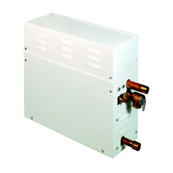
Steam Generator
Install Upright and Level
- 1 -
Models: SM-12 and SM-15
Knock-outs for
Electrical Supply Line
Pub. No. 323-H
C
US
®
LISTED 995C
¾" Steam
Outlet
¾"Safety
Relief Valve
Optional Auto
Drain Installed
Advertisement
Table of Contents

Related Manuals for Steamist SM-12


Summary of Contents for Steamist SM-12
- Page 1 All electrical connections must be performed by a licensed electrician in accordance with Local and National Electric Codes. The Steamist “SM” generator operates with one or two 3. Steam Generator Electrical Installation controls appropriately located inside and/or outside the WARNING: All power to the steam generator must steamroom.
- Page 2 Guide,” or “The Generator Sizing Guide” in the been used. Residential Systems/Steambath Product Information section of the Steamist web site - www.steamist.com. The circuit breaker is NOT a GFI (Ground Fault CAUTION: An improperly sized Steam Generator will Interrupter) type.
- Page 3 The Electrical Instructions must be NOTE: Unit must be wired with given to the homeowner for future use. 90°C wire in a suitable raceway, or, if local codes allow, provide twist lock plug on a 90°C wire cord from generator to a 250V 2 pole, 3-wire grounding receptacle...
- Page 4 SM-12/15 SINGLE PHASE SCHEMATIC Field Connections ** � (Low Voltage) LLC-1300-3 Circuit Board Multi-Conductor Fuse Block Test SENSOR HEAT P18 P17 Cable* TIME START Switch TEMP STOP Contactor / Relay Chart Typical Steamist Control COIL GREY Fuse 0.15 AMP Terminal...
- Page 5 Systems/Steambath Product Steam Outlet - Rough-in the steam line using a Information section of the Steamist web site - minimum of a ¾” copper or brass pipe, do NOT use www.steamist.com. black iron or galvanized pipe, it will rust and discolor the wall of the steam bath.
- Page 6 3. Steam Generator Installation Installation Instruction for Steamhead & Escutcheon (Supplied with control package) The Steam Generator should be mounted in a location convenient for hook-up and service by the Plumber and Be sure the steam pipe is installed with the proper Electrician.
- Page 7 The Plumbing Instructions must be WARNING: When installing the given to the homeowner for future use. Steamist Unit in conjunction with an acrylic modular tub/shower unit, Slope ceiling 2” per foot please consult the “manufacturer of the module” for location of the steamhead.
- Page 8 20” For Area Up To KW Volt Phase Amps Copper AWG Fuse SM-12 SM-15 * Refer to the Steamist Sizing Guide for actual Cu. Ft. capacity. 18” Installation Suggestions Alternate Attic Location (Insulate to Prevent Freezing) TIMER START TEMP START...
- Page 9 Steambath Generators System-30 ® LISTED 995C Master/Slave Installation Instructions Introduction: The System-30 consists of one SM-15 Master and one Master SM-15 Slave. The Master/Slave generators are 15 kilowatts each. This instruction sheet is to be used in conjunction with the standard SM-15 Electrical and Plumbing instructions (Pub.
- Page 10 To Controls IMPORTANT: System-30 To Slave will NOT work with a Unit TC-110 by itself To Control (a Thermostatic Control is needed for this application) Diagram 1 Splitter When using supplied one Control with control To Slave Unit Splitter supplied Splitter with Slave Unit supplied...
- Page 11 For this reason the Optional Auto-Drain can NOT be used with any InstaMist generators. The Steamist InstaMist Feature (-IM) is only available as a factory installed option on the following Models: SM-5, SM-7, SM-8, SM-11, SM-12, SM-15, System-18, System-24, and System-30.
Need help?
Do you have a question about the SM-12 and is the answer not in the manual?
Questions and answers
can a steamist system 30 slave unit run by itself?
No, a Steamist SM-12 system cannot run a Steamist 30 slave unit by itself. The document states that the "System-30 To Slave will NOT work with a Unit TC-110 by itself," implying that additional controls are required. Additionally, the master/slave system requires proper interconnection, and each generator must be separately wired and plumbed.
This answer is automatically generated