Table of Contents
Advertisement
Technical Manual
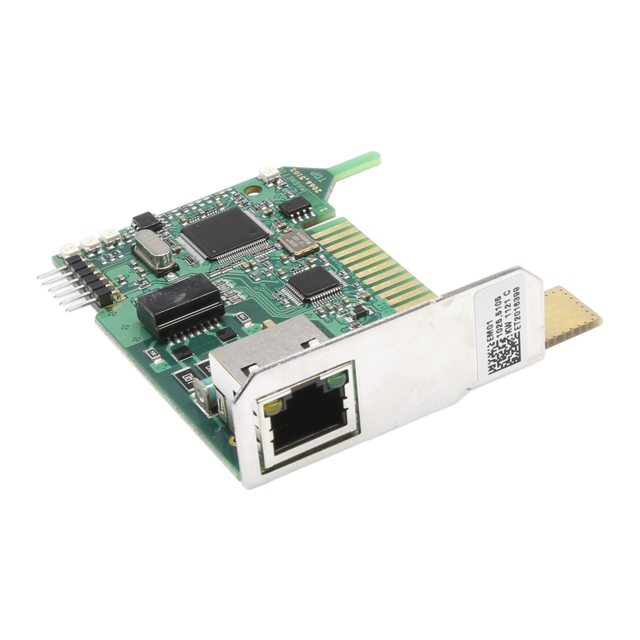
Ethernet Module
MGC-PRO MicroDrive
TM
This technical manual is a supplement to the operating instructions "Barrier MHTM
MicroDrive" (5815,5001) and describes the Ethernet module.
Before using the Ethernet module, read this handbook and the operating instructions
TM
"Barrier MHTM
MicroDrive" carefully!
Doc-ID: 5815,0001EN
Version: 00
Advertisement
Table of Contents

Related Manuals for Magnetic Autocontrol MGC-PRO

Summary of Contents for Magnetic Autocontrol MGC-PRO
- Page 1 Technical Manual Ethernet Module MGC-PRO MicroDrive This technical manual is a supplement to the operating instructions "Barrier MHTM MicroDrive" (5815,5001) and describes the Ethernet module. Before using the Ethernet module, read this handbook and the operating instructions "Barrier MHTM MicroDrive" carefully!
-
Page 2: Table Of Contents
Reference documents............6 Pictogram explanation ...........7 Intended use ..............7 Technical data ................8 Installation and network connection........9 Installing Ethernet module in control unit MGC-PRO ..9 3.1.1 Corrective action ..........10 Perform network connection ........10 Network Configuration ..........10 Menu "Ethernet" of the control unit MGC-PRO ...11 Operation via web interface ..........12... -
Page 3: General
Ethernet Module MGC-PRO MicroDrive General General Information regarding the technical manual This manual offers important information on handling of the Ethernet module. The Ethernet module can only be operated installed in the MAGNETIC MHTM MicroDrive barriers. Prerequisite for secure work is compliance with all indicated safety notes, warning notes and instructions in this manual and in the operating instructions "Barrier MHTM... -
Page 4: Reference Documents
Ethernet Module MGC-PRO MicroDrive General Reference documents NOTE! This technical manual is based on the documents listed in the following table. All listed reference documents are available free of charge via the indicated procurement source. Number Title Author Procurement source 5815,5001 Operating instructions "Barrier... -
Page 5: Pictogram Explanation
Intended use The plug-in module "Ethernet" is exclusively intended for expansion of the MGC-PRO control devices by the function "Ethernet". The plug-in module can only be operated installed in the MAGNETIC MHTM MicroDrive barriers. This plug-in module... -
Page 6: Technical Data
Ethernet Module MGC-PRO MicroDrive Technical data Technical data Designation Unit Value Current consumption Data transfer rate Mbit/s 10 /100 Max. line length: Cable type – Cat-5, Twisted Pair Plug type – RJ-45 Default IP address – 192.168.1.2 Supported services –... -
Page 7: Installation And Network Connection
Ethernet Module MGC-PRO MicroDrive Installation and network connection Installation and network connection Installing Ethernet module in control unit MGC-PRO Hints and recommendations NOTE! The Ethernet module can only be operated with the MAGNETIC control units MGC-PRO. The Ethernet module is installed and set in the factory. Observe the following safety note in case of retrofitting by the customer. -
Page 8: Corrective Action
DHCP is activated by default. The IP address is thus automatically assigned by the customer's DHCP server. The assigned IP address can be called via the display of the MGC-PRO control. If no DHCP server is available, you may deactivate the function via the parameter "DHCP". -
Page 9: Menu "Ethernet" Of The Control Unit Mgc-Pro
Ethernet Module MGC-PRO MicroDrive Installation and network connection Menu "Ethernet" of the control unit MGC-PRO Once the Ethernet module is plugged in and the control unit supplied with power, the menu "Ethernet" appears in the main menu. The position of the menu "Ethernet" in the main menu depends on the other plug-in modules installed and the slot used. -
Page 10: Operation Via Web Interface
Ethernet Module MGC-PRO MicroDrive Operation via web interface Operation via web interface Web interface You can request the conditions of the barrier and operate the barrier via the web interface. The connection is established in the web browser by entering the IP address. - Page 11 Ethernet Module MGC-PRO MicroDrive Operation via web interface Barrier operation (not operational) Fig. 2: Web surface – operation of the barrier (not operational) Barrier settings Fig. 3: Web interface – barrier settings 5815,0001EN / Version 00...
- Page 12 Ethernet Module MGC-PRO MicroDrive Operation via web interface Conditions of the in-/outputs Fig. 4: Web surface – conditions of the in-/outputs Loop overview Fig. 5: Web interface – loop overview 5815,0001EN / Version 00...
- Page 13 Ethernet Module MGC-PRO MicroDrive Operation via web interface Network Configuration Fig. 6: Web interface – network configuration Messages (Reboot) Fig. 7: Web interface – messages (Reboot) 5815,0001EN / Version 00...
-
Page 14: Tcp/Ip Interface
Ethernet Module MGC-PRO MicroDrive TCP/IP Interface TCP/IP Interface Modbus In addition to operation of the barrier via the web interface, communication is possible via the ethernet field bus as Modbus TCP as well. Port 502 is used for Modbus. After the connection between the client (master) and server (slave) is established, the master sends modbus requests to the server. -
Page 15: Address Table
0001 – open 0002 – close 0004 – open high priority 0001 Status 32Bit Barrier status word 16Bit Conditions of the inputs of the MGC-PRO 0003 Inputs control unit Conditions of the outputs of the MGC-PRO 16Bit 0004 Outputs control unit... -
Page 16: Examples
Ethernet Module MGC-PRO MicroDrive TCP/IP Interface 5.1.3 Examples Reading status – request Description Value Transaction ID Protocol ID MBAP Length (Number of following Bytes) Unit ID Function Code (Read Holding Register) Starting Address Quantity of Register Reading status – response... - Page 17 Ethernet Module MGC-PRO MicroDrive TCP/IP Interface Closing barrier – request Description Value Transaction ID Protocol ID MBAP Length (Number of following Bytes) Unit ID Function Code (Write Single Register) Register Address Register Value Closing barrier – response Description Value Transaction ID...
-
Page 18: Expanded Access Via Modbus
Ethernet Module MGC-PRO MicroDrive TCP/IP Interface Opening barrier – request Description Value Transaction ID Protocol ID MBAP Length (Number of following Bytes) Unit ID Function Code (Write Single Register) Register Address Register Value Opening barrier – response Description Value Transaction ID... -
Page 19: Module Addresses
TCP/IP Interface 5.2.2 Module addresses The MGC-PRO control unit is modularly built. Every plug-in module has a unique basic address. The module address is the sum of the basic address and slot number. This enables operation of several equal plug-in modules like two detector modules in the same control unit. -
Page 20: Examples
Ethernet Module MGC-PRO MicroDrive TCP/IP Interface 5.2.4 Examples Reading cycle counter – request Description Value Transaction ID Protocol ID MBAP Length (Number of following Bytes) Unit ID Function Code MEI Type Protocol Control Protocol Option Fields Reserved Field Encoded Data... - Page 21 Ethernet Module MGC-PRO MicroDrive TCP/IP Interface Setting programme mode – Description Value request Transaction ID Protocol ID MBAP Length (Number of following Bytes) Unit ID Function Code MEI Type Protocol Control Protocol Option Fields Reserved Field Encoded Data Node ID...
- Page 22 Ethernet Module MGC-PRO MicroDrive TCP/IP Interface Reading device name module 1 – Description Value request Transaction ID Protocol ID MBAP Length (Number of following Bytes) Unit ID Function Code MEI Type Protocol Control Protocol Option Fields Reserved Field Encoded Data...
-
Page 23: Commissioning
Ethernet Module MGC-PRO MicroDrive Commissioning Commissioning Procedure We recommend the following procedure for initial commissioning: Taking control unit into operation without network cable. Check DHCP settings. Switch off control unit. Connect network cable. Switch on control unit. Read IP address via display. -
Page 24: Appendix
Ethernet Module MGC-PRO MicroDrive Appendix Appendix The description of the status words and object tables are available in document 5815,0000 "MicroDrive MGC/MGC-PRO Additional Information for System integrators". List of abbreviations Abbreviatio Meaning Description Magnetic Gate Controller Control unit for the barriers MicroDrive MHTM... -
Page 25: Index
Ethernet Module MGC-PRO MicroDrive Index Index Logic controller Module address..........21 Address table............17 ADU ..............16 MBAP............16, 26 Menu Cable type ............8 Network settings..........11 CANopen TCP/IP Interface ........20 Menu Ethernet ............11 Closing barrier ............19 Modbus ...............16 Commissioning ...........25 Address table ..........17 Corrective action ADU..............16... - Page 26 Web: www.MagneticGateOpeners.com Phone: (800) 878-7829 Fax: (330) 650-9004 Email: sales@magneticgateopeners.com...
Need help?
Do you have a question about the MGC-PRO and is the answer not in the manual?
Questions and answers