
Related Manuals for Vishay VT300


Summary of Contents for Vishay VT300
- Page 1 VT300 Weighbridge Indicator Technical Manual Revision A4, September 2006 Doc # TM-VT300-EN...
-
Page 2: Table Of Contents
2.3.2 Wall-Mount Model (Stainless Steel) ............. 21 2.3.3 Load Cell Operating Parameters ............21 ................22 ERIAL ONNECTIONS 2.4.1 Printer and PC Cables ................ 22 2.4.2 RS485 Cable Connections ..............22 ................23 ONNECTING OWER VT300 Technical Manual, Rev. A4 Doc # TM-VT300-EN... - Page 3 ............36 OCKING AND NLOCKING ALIBRATION 4.5.1 Sealing Indicator Enclosure with Stickers..........36 Securing Load Receptor ..............37 4.5.2 4.5.3 Checking Seal Status and Audit Trail Counter........37 GENERAL SYSTEM PARAMETERS............. 38 VT300 Technical Manual, Rev. A4 Doc # TM-VT300-EN...
- Page 4 USTOM ICKET ORMATS 6.5.1 Creating a Custom Ticket Format ............58 6.5.2 Downloading and Uploading Custom Ticket Formats....... 60 OUTPUTS AND DIGITAL INPUT............62 .................. 62 PECIFICATIONS 7.1.1 Digital Outputs ................. 62 VT300 Technical Manual, Rev. A4 Doc # TM-VT300-EN...
- Page 5 8.2.3 Testing Digital Input and Outputs (TEST > I/O)........73 8.2.4 Testing Data Received on Both Serial Ports (TEST > PORT)..... 74 SPECIAL WEIGHBRIDGE OPERATIONS ........... 75 ..........75 USTOMIZING EIGHBRIDGE ESCRIPTIONS ................76 ATCH EIGHING TROUBLESHOOTING............... 78 VT300 Technical Manual, Rev. A4 Doc # TM-VT300-EN...
- Page 6 10.1.4 Alibi Memory and Accumulated Total Errors .......... 80 10.2 ............80 HECKING ONNECTION 10.3 ............... 80 HECKING OWER UPPLY 10.4 ..............80 HECKING IGITAL UTPUTS APPENDIX A: TECHNICAL DRAWINGS ............81 CONTACTING VISHAY TRANSDUCERS ............86 VT300 Technical Manual, Rev. A4 Doc # TM-VT300-EN...
-
Page 7: Table Of Figures
..........36 IGURE EAD WIRE SEAL HARD PLASTIC STICKER 10 - W ........... 37 IGURE ALL MOUNT MODEL SEALING INSTRUCTIONS 11 – D ......63 IGURE IGITAL OUTPUT AND TILT SWITCH CONNECTION DIAGRAM VT300 Technical Manual, Rev. A4 Doc # TM-VT300-EN... -
Page 8: Legal Notice
VT protected under international copyright law and shall be and remain solely with VT. VT300 is a registered trademark of VT. No right, license, or interest to such trademark is granted hereunder, and you agree that no such right, license, or interest shall be asserted by you with respect to such trademark. -
Page 9: Warranty
Buyer, and the Purchaser hereby agrees to indemnify and hold Vishay Transducers harmless from any claim asserted against or liability imposed on Vishay Transducers occasioned by the failure of the Purchaser to so notify such Buyer. This provision is not intended to afford subsequent Purchasers any warranties or rights not expressly granted to such subsequent Purchasers under the law. -
Page 10: Safety Instructions
Make sure that all other cables are disconnected before disconnecting the ground. Special Safety Warnings Welding on or in the vicinity of the equipment is strictly prohibited. Use reliable lightening conductors to prevent static loads caused by thunderstorms. VT300 Technical Manual, Rev. A4 Doc # TM-VT300-EN... - Page 11 Fields apparatus. Incoming and Relays and contacts connected to the equipment must have reliable and Outgoing Signals effective interference suppression. This also applies to other equipment within 3 meters of the equipment. VT300 Technical Manual, Rev. A4 Doc # TM-VT300-EN...
-
Page 12: Declaration Of Conformity
Characteristics of Information Technology Equipment. EN 60950:1992, Safety of Information Technology Equipment. April 30, 2004 Date Benny Shaya, Director R&D/Operations Instruments Signature Being the responsible person employed and appointed by Vishay Transducers. VT300 Technical Manual, Rev. A4 Doc # TM-VT300-EN... -
Page 13: About This Document
It is intended for technical staff, and explains how to install, set up and configure the indicator, as well as troubleshoot and service it. For information on how to use the product, see the VT300 User’s Guide. Chapters and Their Contents Technical General indicator specifications;... - Page 14 Notes, which offer an additional explanation or a hint on how to overcome a common problem. Warnings, which indicate potential safety hazards regarding product operation or maintenance to operator or service personnel. VT300 Technical Manual, Rev. A4 Doc # TM-VT300-EN...
-
Page 15: Technical Specifications
Dead load, span and scale parameters via keyboard commands. Calibration can be performed either by weighing or by entering load cell mV values. Self diagnostics Hardware and software – MCU watchdog. Memory failure and I/O failure – program check. VT300 Technical Manual, Rev. A4 Doc # TM-VT300-EN... -
Page 16: Analog Input
0.02-10V. Min load resistance 1KΩ. Resolution • Internal: 16 bits. • External: 16 bits, or in accordance with regulation. Linearity Better than 0.01% of FSR. Thermal stability 50ppm/°C typical. Short-circuit 25mA indefinite duration. protection VT300 Technical Manual, Rev. A4 Doc # TM-VT300-EN... -
Page 17: Digital Input
Off delay 2msec max. 1.5 Digital Outputs Output voltage 24VDC ±10% transistor (source) darlington, positive common. Max current 100mA, leakage current 100µA. Max off-state voltage 30VDC. On delay 2msec max. Off delay 2msec. VT300 Technical Manual, Rev. A4 Doc # TM-VT300-EN... -
Page 18: Installation
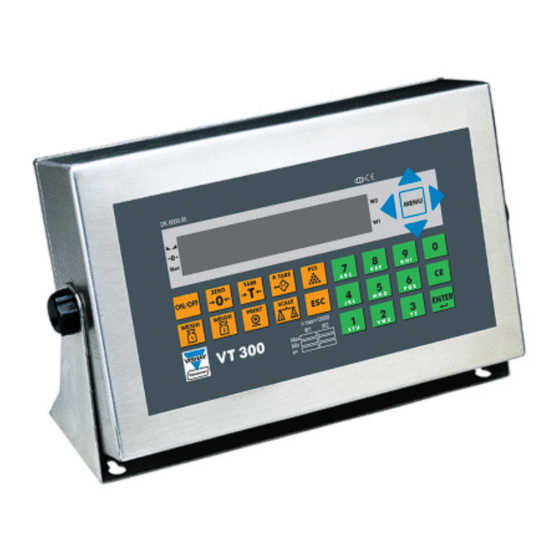
All connections to the instrument are made through the rear panel connectors. Strain- relief clamps should be used. The shield should be connected to the metal frame of the connector. The rear of the VT300 desktop model is shown in Figure 1. Figure 1 – Desktop model, front and rear view VT300 Technical Manual, Rev. -
Page 19: Wall-Mount Model (Stainless Steel Enclosure)
2.3, 2.4 and 2.5. 3. Connect the cable shield, either between the plastic and the metal case of the cable glands, or to the screws supporting the PCBs. 4. Re-install the rear panel. VT300 Technical Manual, Rev. A4 Doc # TM-VT300-EN... -
Page 20: Connecting Load Cells
2 (DB15 F) Description Calibration Enable Excitation (-) Sense (-) Sense (+) Excitation (+) Signal (-) Signal (+) D-Type Metal Case (Shield) Figure 3 – Load cell connection diagram for desktop model VT300 Technical Manual, Rev. A4 Doc # TM-VT300-EN... -
Page 21: Wall-Mount Model (Stainless Steel)
Do not run signal cables together with power cables. Connect the shielding only where indicated in the drawing. Never use a Megger to check wiring. Never use plastic insulating tape on load cell connections. VT300 Technical Manual, Rev. A4 Doc # TM-VT300-EN... -
Page 22: Serial Connections
The terminal block on the RS485 board enables connecting two pairs of wires (A, B): One wire pair for connecting the incoming cable. A second wire pair for a daisy-chain connection to the next unit on the RS485 bus. VT300 Technical Manual, Rev. A4 Doc # TM-VT300-EN... -
Page 23: Connecting Power
Figure 6 – RS485 cable connection diagram 2.5 Connecting Power VT300 indicators are powered by 85-265VAC, via an internal power supply board. The mains power cable is supplied with the instrument. Power should be isolated from other data processing equipment. -
Page 24: Display, Keys And Menus
3.1 The Display The VT300 has an LCD display. There are three status annunciators on the left of the display and two more on the right of the display. Small dots (status annunciators) may appear next to one or more of these, to show status information such as whether the scale has been tared or not. -
Page 25: Status Annunciators
Automatic zeroing, performed at the end of the power-up sequence. ZERO SCALE Other types of messages may be shown when you perform specific operations, such as editing the tare value or displaying battery status. VT300 Technical Manual, Rev. A4 Doc # TM-VT300-EN... -
Page 26: Front Panel Keys
Display, Keys and Menus Front Panel Keys 3.2 Front Panel Keys The keys on the VT300 front panel can serve two functions: Performing common operations and accessing the menu. Entering alphanumeric information. Using Keys to Perform Operations 3.2.1 Description Related operations Refer to Press to zero the scale*. -
Page 27: Using Keys To Enter Information
4. Press ESC to return to a higher menu or submenu level. 5. When you reach the desired menu option, press ENTER to confirm. VT300 Technical Manual, Rev. A4 Doc # TM-VT300-EN... -
Page 28: Menu Structure And Options Summary
7.1.1 Shows or prints specific alibi memory User’s Guide, ALIBI VIEW records. section 8.1 Prints entire alibi memory. User’s Guide, PRINT section 8.2 Alibi memory functions. User’s Guide, CSUM section 8.3 VT300 Technical Manual, Rev. A4 Doc # TM-VT300-EN... -
Page 29: Main > Vfile
Subtotal of net weights. Press PRINT to print, CE to reset. User’s Guide, STOT section 4.3.2 Accumulated total of net weights. Press PRINT to print, CE to reset. User’s Guide, TOTAL section 4.3.2 VT300 Technical Manual, Rev. A4 Doc # TM-VT300-EN... -
Page 30: Main > Misc
ZERO 4.3.2 Maximum weight calibration for scale 2. Sections 4.2.2, SPAN 4.3.3 Resets calibration parameters for scale 2. Section 8.1.3 INIT Stores scale 2 calibration parameters in Section 4.4 WRITE persistent memory. VT300 Technical Manual, Rev. A4 Doc # TM-VT300-EN... -
Page 31: Main > System (Cont.)
Shows load cell mV output. Section 8.1.6 Tests outputs and digital input. Section 8.2.3 Tests keypad. Section 8.2.2 Tests display. Section 8.2.2 Tests ROM/RAM integrity. Section 8.2.1 Tests communication ports. Section 8.2.4 PORT VT300 Technical Manual, Rev. A4 Doc # TM-VT300-EN... -
Page 32: Calibration
ELECTR – electronic calibration. 4. Press ENTER to confirm your selection. If you selected WEIGHT, proceed to section 4.2 to perform standard calibration. If you selected ELECTR, proceed to section 4.3 to perform electronic calibration. VT300 Technical Manual, Rev. A4 Doc # TM-VT300-EN... -
Page 33: Calibration With Standard Weights
5. Press ENTER. The display shows WAIT… as 64 measurements are taken and the span coefficient calculated. This should take about 10 seconds. 6. Span calibration is now complete. If the weight shown is not accurate, press ESC and go back to step 1. VT300 Technical Manual, Rev. A4 Doc # TM-VT300-EN... -
Page 34: Electronic Calibration (E-Cal)
3. Calculate an average of the load cells’ zero balance. In the example above, this equals [0.0257+0.0276+0.0553+(- 0.0022)]/4=0.0266mV. 4. Calculate the scale dead-load. In the example above, this equals 1.9600mV*[1.940Kg/(4*50Kg)]=0.0190mV. VT300 Technical Manual, Rev. A4 Doc # TM-VT300-EN... -
Page 35: Setting Zero Calibration (Dead-Load) Value
2, navigate to SYSTEM > 2CAL > WRITE. 2. Press ENTER. The display shows O.K.? AE=Y , CE=N. 3. Press ENTER to confirm. Calibration data is stored in persistent memory, and the indicator restarts. VT300 Technical Manual, Rev. A4 Doc # TM-VT300-EN... -
Page 36: Locking And Unlocking Calibration
A lead wire seal or hard plastic sticker, to prevent unauthorized tampering with the load cell connector (Figure 9) Figure 8 – Non-removable sticker Figure 9 – Lead wire seal / hard plastic sticker VT300 Technical Manual, Rev. A4 Doc # TM-VT300-EN... -
Page 37: Securing Load Receptor
MISC > 2OIML. 2. Press ENTER. If JP1 is currently in the sealed position, the word SEALED appears on the display briefly. Following this, the audit trail counter is displayed. VT300 Technical Manual, Rev. A4 Doc # TM-VT300-EN... -
Page 38: General System Parameters
4. If the parameter is in the 1CAL > PAR or 2CAL > PAR menu, you must perform a WRITE operation to save the new settings to persistent memory (see section 4.4). VT300 Technical Manual, Rev. A4 Doc # TM-VT300-EN... -
Page 39: System > 1/2Cal > Par Menu
YES specifies that A/D converter errors should remain on the display until the operator presses ESC. BATTERY Battery conversion. Enables battery conversion, for YES, NO battery-powered models. VT300 Technical Manual, Rev. A4 Doc # TM-VT300-EN... - Page 40 1/2CAL > ZERO and 1/2CAL > SPAN. UNIT SELECT Unit selection. Specifies unit used for measurement: KG, LB kilograms or pounds. * Refer to Section 5.2.1 for how to set parameters when using two scales. VT300 Technical Manual, Rev. A4 Doc # TM-VT300-EN...
-
Page 41: Dual-Scale Connecting And Parameter Settings
SYSTEM > SET > OPER Dual-scale Connecting And Parameter Settings 5.2.1 To connect and set up VT300 for dual-scale operations: 1. Set parameter 2SCL ENABLE(00) to YES, DUAL RANGE(19) to 00, and CONV.RATE (07) to a value less than 70. - Page 42 (“-”). AUTO PWR OFF Power off interval. Specifies the idle time, in minutes, 00-99 that should pass before the indicator automatically 00=disable switches itself off. power off VT300 Technical Manual, Rev. A4 Doc # TM-VT300-EN...
-
Page 43: Serial Communication
6 Serial Communication 6.1 Serial Ports Configuration VT300 has two serial ports, designated port 1 and port 2. Port 1 is an RS232 port. Port 2 is an optional port installed on order, and can be either RS232 or RS485. -
Page 44: Setting Port Output
NO specifies that errors should be ignored. You must set this parameter to NO for communication with a PC. ADDRESS Port 1 network address. Used in alibi mode. This can be different from the address set in 2COM > M/S. VT300 Technical Manual, Rev. A4 Doc # TM-VT300-EN... -
Page 45: Setting Port 2 Output
YES specifies that printer errors (DTR) should be displayed and acknowledged by the user. NO specifies that errors should be ignored. You must set this parameter to NO for communication with a PC. VT300 Technical Manual, Rev. A4 Doc # TM-VT300-EN... -
Page 46: Output Formats
1=Under minimum weighing range Bit6 Always 1 Bit7 Zero or parity Polarity “+” or “-”. Weight 6 digits, including decimal point if any Sync Carriage return (0D hex) for end of transmission. VT300 Technical Manual, Rev. A4 Doc # TM-VT300-EN... -
Page 47: Continuous Weight Output With Dual Scale Operation
This option can be programmed using setup parameter SYSTEM > SET > 2COM > OPERATION to A.OUT. The weight indication of each scale is transmitted continuously along with its current tare and gross weight. The format is: VT300 Technical Manual, Rev. A4 Doc # TM-VT300-EN... - Page 48 When the indicator displays something other than weight, the data string to COM2 will be as follows: |A|XXXX|TARE VALUE|T/P|GROSS VALUE|G|CR “XXXX” in the format above will either be blank spaces, an error message, or the menu currently accessed by the user. VT300 Technical Manual, Rev. A4 Doc # TM-VT300-EN...
-
Page 49: Alibi Transmit
Equivalent to pressing the front panel ZERO key. This is executed when ASCII character 0 (30 hex) is received. No data is returned to the host. Execution of the command may be verified by examining the weight (command “?”). VT300 Technical Manual, Rev. A4 Doc # TM-VT300-EN... -
Page 50: Character For Print-On-Demand
SYSTEM > 2COM > EDP > PROTO A/N (YES/NO) – handshake. Turning off handshake removes steps 4 and 5 of the protocol workflow - the indicator sends data blocks on demand, without waiting for a response. VT300 Technical Manual, Rev. A4 Doc # TM-VT300-EN... -
Page 51: Remote Printer Output
A [41h] and Y [59h]). The SYSTEM > SET > 2COM > OPERATION > M/S A submenu has several other options, beside the network address parameter. These are described below. VT300 Technical Manual, Rev. A4 Doc # TM-VT300-EN... - Page 52 Slave w/remote memory Slave w/local and remote memory TYPE / ADDRESS 65-89 (A-Y) 65-89 (A-Y) 65-89 (A-Y) ERROR CTRL YES/NO YES/NO YES/NO RETRY YES/NO YES/NO DIS. PROTO YES/NO YES/NO X/MIT RESULT YES/NO YES/NO YES/NO VT300 Technical Manual, Rev. A4 Doc # TM-VT300-EN...
-
Page 53: Master-Slave Commands
WEIGHT BCS2 BCS1 WEIGHT = 5 digits + decimal point if any.(ASCII,MSD FIRST) X = Scale number 0 = Scale 1 + Scale 2 1 = Scale 1 2 = Scale 2 VT300 Technical Manual, Rev. A4 Doc # TM-VT300-EN... - Page 54 The slave response will contain a message in place of the weight if b0 of the status byte is high. @ Reset Slave Resets the slave. Master Transmission BCS2 BCS1 Slave Response None. VT300 Technical Manual, Rev. A4 Doc # TM-VT300-EN...
- Page 55 6 – PRINT 1A – PCS 17 – WEIGH1 18 – WEIGH2 5d – ENTER 30-39 – numeric keypad, 0-9 1b – MENU 0B - 08 - 09 - 05 - Slave Response None. VT300 Technical Manual, Rev. A4 Doc # TM-VT300-EN...
-
Page 56: Gross-Tare-Net Weight Transmission
“P” specifies that the preceding weight is a preset tare. 17-22 Gross weight 6 digits, including decimal point if any “G” Indicates that the preceding weight is gross. Scale number Either 1 or 2. VT300 Technical Manual, Rev. A4 Doc # TM-VT300-EN... -
Page 57: Default Ticket Formats
Default Ticket Formats 6.4 Default Ticket Formats The VT300 has four print formats, shown in the table below. These print formats are not interchangeable – each one is used for a specific purpose. Each print format is identified by a ticket number. -
Page 58: Custom Ticket Formats
When you follow the procedure for downloading a custom print format (see section 6.5.2 below), the indicator uploads the default print format to the PC, as an ASCII file. You can edit this file to create the custom print format. VT300 Technical Manual, Rev. A4 Doc # TM-VT300-EN... - Page 59 [!035] – CODE 1 data*. [!036] – CODE 2 prompt*. [!037] – CODE 2 data*. [!038] – CODE 3 prompt*. [!039] – CODE 3 data*. [!040] – CODE 4 prompt*. [!041] – CODE 4 data*. VT300 Technical Manual, Rev. A4 Doc # TM-VT300-EN...
-
Page 60: Downloading And Uploading Custom Ticket Formats
Downloading and Uploading Custom Ticket Formats 6.5.2 The VT300 has four tickets; their standard formats are shown in the table in section 6.4. You can replace any of these tickets with a custom format, which is downloaded from a PC. The custom ticket format must be an ASCII file 1023 bytes or less in length (see the previous section for more details). - Page 61 PC for verification. The received ticket is stored in non-volatile memory. 11. On the PC, check the ASCII block sent by the indicator, to ensure communication was successful. If not, go back to step 3. VT300 Technical Manual, Rev. A4 Doc # TM-VT300-EN...
-
Page 62: Outputs And Digital Input
Outputs and Digital Input Specifications 7 Outputs and Digital Input The VT300 is able to interface with weighing automation systems, using two optoisolated outputs (digital setpoints) and one digital input. There is also an analog output configuration. The digital outputs (setpoints) are triggered when the scale reads an upper weight threshold, defined by the user. -
Page 63: Connecting Digital Outputs And Tilt Switch
If you do not want to change this threshold, press ESC. If you do want to change it, proceed to the next step. 4. Enter a new threshold value using the numeric keypad, and press ENTER. VT300 Technical Manual, Rev. A4 Doc # TM-VT300-EN... -
Page 64: Setpoint Options
2.3=0 and 2.4=0: normal SETP 2.4 2.3=1 and 2.4=0: zero 2.3=0 and 2.4=1: net Net / gross for both setpoints. 0=net 1=gross Normally open / closed for both 0=normally open setpoints. 1=normally closed VT300 Technical Manual, Rev. A4 Doc # TM-VT300-EN... -
Page 65: Configuring Analog Output
For voltage output, connect pin 2 (voltage output, +) and pin 3 (common). 2. Connect an external power supply of 24VDC, using pins 4 and 5: Pin 4 – power in (+). Pin 5 – power in (-). VT300 Technical Manual, Rev. A4 Doc # TM-VT300-EN... -
Page 66: Setting Analog Output Parameters
(see section 7.4.1). MODE Net / gross. Specifies whether the indicator should always NET, GROSS output gross weight, or output net weight when tare is active. VT300 Technical Manual, Rev. A4 Doc # TM-VT300-EN... -
Page 67: Calibrating D/A Converter
11. When prompted for D/A span, enter the full scale voltage you calculated in step 7. 12. When you finish stepping through the dialog, exit the menu. 13. Access SYSTEM > 1CAL > WRITE to save your settings. VT300 Technical Manual, Rev. A4 Doc # TM-VT300-EN... -
Page 68: Using The Tilt Switch
If input is low, setpoints are inactive. 95 – When input is low, scale 1 is selected and displayed. When input is high, scale 2 is selected and displayed. 96 – Scale is reset to 0. VT300 Technical Manual, Rev. A4 Doc # TM-VT300-EN... -
Page 69: Service Operations And Testing
Setting and Changing System and Operator Password (SYSTEM 8.1.1 > PIN) The VT300 has two Personal Identification Numbers (PINs): A “system PIN”, which restricts access to the SYSTEM menu. This menu contains the calibration menus, so this also functions as the calibration PIN. -
Page 70: Setting Date, Time And Serial Number (System > Date)
Press MENU and navigate to one of the following, depending on the group of parameters you wish to reset: Access SYSTEM > 1CAL > INIT to reset all calibration parameters, and general parameters in the PAR submenu (see section 5.2), pertaining to scale 1. VT300 Technical Manual, Rev. A4 Doc # TM-VT300-EN... -
Page 71: Displaying Remaining Battery Capacity (Weigh > Battery)
Viewing A/D Count (TEST > A/D) 8.1.7 To view the A/D count: Press MENU and navigate to SYSTEM > TEST > A/D. The indicator shows the analog-to-digital converter internal count. Press ESC to exit. VT300 Technical Manual, Rev. A4 Doc # TM-VT300-EN... -
Page 72: Locking And Unlocking Keys
2. One of the following messages are displayed: Err 01 – indicates that ROM data is corrupted. Err 02 – indicates that RAM data is corrupted. PASS – indicates that both the ROM and RAM memory units are okay. VT300 Technical Manual, Rev. A4 Doc # TM-VT300-EN... -
Page 73: Testing The Keypad And Display (Test > Kbd, Lcd)
The digit next to the word INP shows data received on the digital input. The most significant digit next to the word OUT shows data sent on digital output 1, when you toggle it on (see step 3). VT300 Technical Manual, Rev. A4 Doc # TM-VT300-EN... -
Page 74: Testing Data Received On Both Serial Ports (Test > Port)
Rx2 is data received on port 2, in ASCII Hex. 3. Connect a PC or another device to one or both of the indicator’s ports, and begin transmitting data. Watch the display to see if the data is received properly. VT300 Technical Manual, Rev. A4 Doc # TM-VT300-EN... -
Page 75: Special Weighbridge Operations
This section assumes you are familiar with VT300 weighbridge functionality. If not, refer to the VT300 User’s Guide, chapter 6. When users weigh a vehicle using the VT300, they are prompted for information on the vehicle, also known as weighbridge descriptions, or reference codes. -
Page 76: Batch Weighing
04.330kg 000009.050kg 0004 04.330kg 000013.380kg 0005 04.330kg 000017.710kg 0006 04.330kg 000022.040kg 0007 04.330kg 000026.370kg 0008 04.330kg 000030.700kg 0009 04.330kg 000035.030kg 0010 04.330kg 000039.360kg 0011 04.330kg 000043.690kg 0012 04.330kg 000048.020kg 0013 04.330kg 000052.350kg VT300 Technical Manual, Rev. A4 Doc # TM-VT300-EN... - Page 77 3. Perform a regular weighing. 4. Press PRINT. A single line is added to the ticket. 5. Repeat steps 3 and 4 for each additional weighing. 6. When you are done, press ESC. VT300 Technical Manual, Rev. A4 Doc # TM-VT300-EN...
-
Page 78: Troubleshooting
Zero the scale. due to power failure or soft reset. E16: W DATE TIME System not initialized Enter a new date and time using SYSTEM > DATE. Replace battery. properly, or backup battery failure. VT300 Technical Manual, Rev. A4 Doc # TM-VT300-EN... -
Page 79: Printing And Edp Protocol Errors
E47:OUT OF LIMIT Weight is out of limits. Retry. E50:SAMPLE CNT The sample used in counting Retry. has too few units. E51:SAMPLE WEIGH The sample used in counting Retry. weighs too little. VT300 Technical Manual, Rev. A4 Doc # TM-VT300-EN... -
Page 80: Alibi Memory And Accumulated Total Errors
Check the resettable fuse F4 on PCB 801. 10.4 Checking Digital Outputs If the setpoints are not working properly: Test the setpoints (see section 8.2.3). Check 24VDC power supply. Check the resettable fuse F3 on PCB 801. VT300 Technical Manual, Rev. A4 Doc # TM-VT300-EN... -
Page 81: Appendix A: Technical Drawings
Power Power Input Power Analog 0-10VDC or Input Filter Supply Output 9-15VDC 0-20mADC Analog to Power On-Off Digital 24VDC PCB 801 EXTERNAL Conv. (ST9) J4 Sel. Current or Voltage Output PCB 761 VT300 Technical Manual, Rev. A4 Doc # TM-VT300-EN... - Page 82 Signal (+) Output 2 Power in D-Type Metal Case D-Type Metal Case 5,13 NOTE: Short pins Output (Shield) (Shield) 8,9 for termination Common (+) resistor (120R) D-Type Metal Case Calibration connection (Shield) Enable VT300 Technical Manual, Rev. A4 Doc # TM-VT300-EN...
- Page 83 - EX +SEN –SEN –EX IOUT+ TER. SEL. VOUT+ VOUT- or IOUT- SGND POWER IN (24 VDC) SHLD NOTE: PCBs are drawn as Select Current or viewed in the housing. Voltage Output VT300 Technical Manual, Rev. A4 Doc # TM-VT300-EN...
- Page 84 Case Max 15m Digital Outputs Power & BRN GND Imax=100m To VTx00 Setpoints GND BRN RS232 Connector Connector WHI DTR DTR WHI & T & PC C IGITAL UTPUTS ONNECTIONS RINTER ABLES VT300 Technical Manual, Rev. A4 Doc # TM-VT300-EN...
- Page 85 Appendix A: Technical Drawings v. Printed Circuit Boards v. Printed Circuit Boards VT300 Technical Manual, Rev. A4 Doc # TM-VT300-EN...
-
Page 86: Contacting Vishay Transducers
FAX: +1-416-251-2690 E-MAIL: vt.us@vishaymg.com E-MAIL: vt.can@vishaymg.com Asia Vishay Transducers Taiwan (Asia except China) Vishay Tranducers China 15 Fl, No. 86, Sec. 1 Shintal 5 No. 5 Binguan Nan Dao Youyi Rd., Hexi District, Shijr City, Taipei, Taiwan 221 Tianjin China, Code 300061...
Need help?
Do you have a question about the VT300 and is the answer not in the manual?
Questions and answers