Table of Contents
Advertisement
Quick Links
The capacity of a single 2000 IPS Peripheral Interface Module (PIM) is 64 TDM ports and 448 IP
extension ports. With a maximum of 8 modules a complete system can be built of up to 512 TDM
ports and a capacity of 1020 virtual (IP + TDM) stations .
A smaller version, the 2000 IPS DM, is positioned more for the IT environment: it is housed in a
thin PC like chassis for 19" rack mounting and each chassis only occupies two Rack Units (2RU).
It supports up to 40 TDM ports (in a single module) but has capacity to the full 448 IP extension
ports. Up to three chassis can be stacked providing maximum capacity of 120 legacy TDM ports
while still supporting as many as 320 peer-to-peer IP stations. It uses the same CPU, line/trunk
cards, application processor cards and software of the SOPHO 2000 IPS.
The remote PIM concept is combining the benefits of distributed networking with full feature
transparency, without giving up reliability. Especially for this concept also the DM-remote (DMR)
is introduced. With the Remote PIM the IP station capacity is expanded from 448 -> 956.
Trunk Features: Analogue trunk, ISDN and SIP Trunk Interface for Germany (Toplink)
Tie lines: QSIG and CCIS, a proprietary tie-line protocol
Mobility Access (Basic + Enquiry Calls)
In-skin Voice Mail / Unified Messaging, NAT/NAPT support
SMDR over IP, PMS over IP, Fax over IP (FoIP), Modem over IP (MoIP)
CSTA interface: OAI providing call monitoring and control for external applications
Benefits:
Advanced Technology (complete IP system on one card)
Supports TDM & IP Switching
Peer-to-Peer IP Telephony Connectivity
NEC Philips Unified Solutions
Reproduction in whole or in part is prohibited without the written consent of the copyright owner.
Subject:
Release:
Date:
The SOPHO 2000 IPS provides the flexibility of
the existing TDM-technology, with over 400
features, while providing a bridge to the IP-
technology of the future. The SOPHO 2000 IPS
was the first IP Telephony system that supports
100% peer-to-peer connectivity and offers all the
system reliability and features associated with
traditional TDM PBXs.
UPD
© NEC Philips Unified Solutions, 2006. All right reserved.
General Product Description
Sopho 2000 IPS, IPS DM
Release 12.2, August 2006
SOPHO 2000 IPS and IPS DM
up to 12.2
August 2006
1 of 259
Advertisement
Table of Contents

Related Manuals for NEC SOPHO 2000 IPS


Summary of Contents for NEC SOPHO 2000 IPS
- Page 1 320 peer-to-peer IP stations. It uses the same CPU, line/trunk cards, application processor cards and software of the SOPHO 2000 IPS. The remote PIM concept is combining the benefits of distributed networking with full feature transparency, without giving up reliability.
- Page 2 NEC Philips Unified Solutions reserves the right to change the specifications, functions, or features, at any time, without notice. NEC Philips Unified Solutions has prepared this document for use by its employees and customers. The information contained herein is the property of NEC Philips Unified Solutions and shall not be reproduced without prior written approval from NEC Philips Unified Solutions ®...
-
Page 3: Table Of Contents
........................... 12 UTURE 2000 IPS................ 14 YSTEM INFORMATION OPHO 1.3.1 The IP nature of SOPHO 2000 IPS ................15 1.3.1.1 Peer-to-Peer IP Telephony Connectivity ............16 1.3.1.2 Peer-to-Peer IP Connectivity in the LAN / WAN..........17 1.3.2 Voice Mail (MyMail@Net 510i)................17 1.3.3... - Page 4 Release 12.2, August 2006 2.3.1 Port Interface Module (PIM) ..................33 2.3.2 Battery Module (BATTMH) ..................34 2.3.3 Installation Hardware ....................34 2.3.4 SOPHO 2000 IPS SYSTEM POWER SUPPLY ............35 ......................35 IRCUIT ARDS IPS S ....................36 YSTEM ONDITIONS IPS T ...................
- Page 5 ANEL 4.16 IPS DM ....................114 PARE PARTS NEC Philips Unified Solutions 5 of 259 © NEC Philips Unified Solutions, 2006. All right reserved. Reproduction in whole or in part is prohibited without the written consent of the copyright owner.
- Page 6 Log Data Collection for VoIP Calls (R10) ............ 211 NEC Philips Unified Solutions 6 of 259 © NEC Philips Unified Solutions, 2006. All right reserved. Reproduction in whole or in part is prohibited without the written consent of the copyright owner.
- Page 7 7.6.1 E&M TIE LINES ..................... 234 7.6.2 Analogue Trunk interface, Transmission Plan (R9)..........234 7.6.3 SIP Trunk with Toplink, Germany, Basic calls (R11)..........235 SOPHO 2000 IPS DM, IPS DML, IPS DMR S ..... 236 YSTEM PECIFICATIONS ......................237 ONDITIONS ......................
- Page 8 Channel Allocation Table ..................... 251 SPN-8IPLA and SPZ-24IPLA Specifications:..............252 SPN-8IPLA and SPZ-24IPLA Number of simultaneous calls (Estimated) ......253 SOPHO 2000 IPS IP PAD Mounting Conditions ..............255 SOPHO IPS DM and SOPHO IPS DMR Mounting Conditions........... 257 NEC Philips Unified Solutions 8 of 259 ©...
-
Page 9: Regulatory Information
Another consequence is that the H.323 trunk interface will be abandoned in favor of SIP trunking. NEC Philips Unified Solutions 9 of 259 © NEC Philips Unified Solutions, 2006. All right reserved. Reproduction in whole or in part is prohibited without the written consent of the copyright owner. -
Page 10: Service Requirements
In the event of equipment malfunction, all repairs will be performed by NEC Philips Unified Solutions or an authorized distributor. It is the responsibility of users requiring service to report the need for service to NEC Philips Unified Solutions or to one of their authorized distributors. -
Page 11: Introduction
TDM PBXs. The SOPHO 2000 IPS delivers the same rich feature set as any traditional PBX, but with the added functionality of supporting peer-to-peer IP switching alongside TDM switching. This protects users’... -
Page 12: Future
SOPHO 2000 IPS release 12.2 The SOPHO 2000 IPS continues to provide new and enhanced features with the release of 3700 series R12.2 software, such as Remote MP software download/upgrade (for DMR in Remote PIM system), Delayed Hotline and Automatic Login to Home Station Number. In addition, there are enhancements on Mobility Access, OAI (to improve call handling by PC-based attendant), SIP trunks, Dial-by-Name, etc. - Page 13 Once available and supported this document will be updated. NEC Philips Unified Solutions 13 of 259 © NEC Philips Unified Solutions, 2006. All right reserved. Reproduction in whole or in part is prohibited without the written consent of the copyright owner.
-
Page 14: System Information Sopho 2000 Ips
Device Registration Server (DRS) and a single interface point of IP connection to IP telephone, MATWorX, and OAI/ACD servers. SOPHO 2000 IPS users have access to hundreds of service features that are used in building unique telephony applications that enhance productivity, reduce operating costs and improve communications efficiently. -
Page 15: The Ip Nature Of Sopho 2000 Ips
General Product Description Sopho 2000IPS Release 12.2, August 2006 SOPHO 2000 IPS/ IPS DM nodes giving all users the look and feel of “one network.” Up to 255 SOPHO 2000 IPS nodes can be networked together. Note: DPNSS is not supported 1.3.1 The IP nature of SOPHO 2000 IPS... -
Page 16: Peer-To-Peer Ip Telephony Connectivity
Time Division Multiplexed (TDM) switching engine. The SOPHO 2000 IPS assists in the call setup process and provides the full range of traditional telephony features. Once the call is established, the “voice”-data is “carried”... -
Page 17: Peer-To-Peer Ip Connectivity In The Lan / Wan
Access Points in VoIP terminology) communicate with the system via the LAN infrastructure. The Philips SOPHO 2000 IPS provides a unique set of features with DECT terminals. A choice of business phones is available, enabling individual user needs to be met. -
Page 18: Sopho Business Connect
Auto-attendant/IVR, caller identification and complete supervisor functions. NEC Philips Unified Solutions 18 of 259 © NEC Philips Unified Solutions, 2006. All right reserved. Reproduction in whole or in part is prohibited without the written consent of the copyright owner. -
Page 19: Hardware Architecture
Time Division Switching (TDM). The pure IP switching is provided for communications between DtermIPs and for CCIS/Remote PIM connections with another SOPHO 2000 IPS/ SOPHO 2000 IPS DM/ SOPHO 2000 IPS DML/ iS3000. On the other hand, the TDM switching is provided for communications between legacy stations/trunks. -
Page 20: Firmware Processor (Fp)
PIM. This maximizes the efficiency of slot utilization of the PIM. High Density Line/Trunk Cards 1.4.6 High Density Line/Trunk Cards The major line/trunk cards used in the SOPHO 2000 IPS are provided with 8 circuits per card. This allows the physical system size to be compact. NEC Philips Unified Solutions 20 of 259 ©... -
Page 21: Extended Application Processor (Ap) Port Capacity
1.4.14 Remote PIM over IP with Survivability The SOPHO 2000 IPS can have a PIM installed at a remote site through an IP network. At the main site, the SOPHO 2000 IPS/IPS DM is installed and SOPHO 2000 IPS /IPS DMR are installed at the remote site. -
Page 22: Software Architecture
Expands T1/E1 capacity between 144 to 240 channels NEC Philips Unified Solutions 22 of 259 © NEC Philips Unified Solutions, 2006. All right reserved. Reproduction in whole or in part is prohibited without the written consent of the copyright owner. - Page 23 Soft-Phone Licenses and 8 IP SeatLicenses. NEC Philips Unified Solutions 23 of 259 © NEC Philips Unified Solutions, 2006. All right reserved. Reproduction in whole or in part is prohibited without the written consent of the copyright owner.
-
Page 24: Technical Terms
(for Single Line Telephone) AP00 SMDR/Hotel Application Card Optical Interface Card NEC Philips Unified Solutions 24 of 259 © NEC Philips Unified Solutions, 2006. All right reserved. Reproduction in whole or in part is prohibited without the written consent of the copyright owner. -
Page 25: Trunking Diagram
General Product Description Sopho 2000IPS Release 12.2, August 2006 1.7 Trunking Diagram This figure shows a typical trunking diagram of the SOPHO 2000 IPS system (some items are not available in EMEA): NEC Philips Unified Solutions 25 of 259 © NEC Philips Unified Solutions, 2006. All right reserved. -
Page 26: Sopho Ips Dm
PSTN. Pure IP switching provides communications between Dterm IP phones and also provides CCIS network connections with up to 255 SOPHO 2000 IPS and other SOPHO IPS DM systems. TDM switching provides for communication between legacy stations and trunks. -
Page 27: Characteristics Of The Sopho Ips Dm And Ips Dml
Power Failure Transfer (PFT) Power Failure Transfer (PFT) for the IPS DM/IPS DML is provided with PZ-4PFTA card. The PZ-8PFTB for the SOPHO 2000 IPS is not available for the IPS DM/IPS DML. Installation Methods Wall Mount Installation is not available. The SOPHO IPS DM /IPS DML can be installed on the desktop or into the 19-inch rack. - Page 28 Remote Site, rather than DtermIP at remote location or the Media Converter (MC) accommodation. NEC Philips Unified Solutions 28 of 259 © NEC Philips Unified Solutions, 2006. All right reserved. Reproduction in whole or in part is prohibited without the written consent of the copyright owner.
-
Page 29: List Of Main Benefits
Capitalize on Converged LAN Infrastructures – Similarly, the SOPHO 2000 IPS allows users to establish voice calls across the 10/100 Ethernet Local Area Network utilising the existing plant cabling and allowing single cable termination to the desktop. -
Page 30: System Configurations
Flash ROM technology and high reliability. The SOPHO 2000 IPS consists of a single or multiple Port Interface Modules (PIM), depending on the system configuration; there are two types of PIMs; “Physical” PIM and “Virtual”... - Page 31 I/O Bus and PCM BUS. NEC Philips Unified Solutions 31 of 259 © NEC Philips Unified Solutions, 2006. All right reserved. Reproduction in whole or in part is prohibited without the written consent of the copyright owner.
-
Page 32: Installation Methods
Wall Mounting Installation 19-inch Rack Mounting Installation 2.2.1 Floor Standing Installation In Floor Standing Installation, the SOPHO 2000 IPS is comprised of up to 8 Port Interface Modules (PIMs). 2.2.2 Wall-mounting Installation The SOPHO 2000 IPS can be wall- mounted with single or multiple PIM configurations (maximum of eight PIMs). -
Page 33: Inch Rack-Mounting Installation
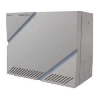
2.3 Modules and Installation Hardware 2.3.1 Port Interface Module (PIM) The SOPHO 2000 IPS is comprised of up to 8 Port Interface Modules (PIMs). A PIM provides 13 card slots for common control, Line/Trunk (LT), and Application Processor (AP) cards. It also houses an AC/DC Power Supply, DC/DC Power Supply (for -48V), and batteries for protection from short-term (about 30 min.) power interruption. -
Page 34: Battery Module (Battmh)
(UL complied). One set of Base Tray Assembly is required for each stack. NEC Philips Unified Solutions 34 of 259 © NEC Philips Unified Solutions, 2006. All right reserved. Reproduction in whole or in part is prohibited without the written consent of the copyright owner. -
Page 35: Sopho 2000 Ips System Power Supply
The battery shall be locally provided. 2.4 Circuit Cards The circuit cards used for SOPHO 2000 IPS are divided into the following three types. According to these card types, the mounting locations of card and port allocation of the Time Division Switch are varied. -
Page 36: Ips System Conditions
2.6 IPS Terminal interfaces 2.6.1 ANALOGUE STATION INTERFACE The SOPHO 2000 IPS supports analogue stations with an 8 port (max. 600 ohms loop resistance) card or a long-line 4 port (max. 2500 ohms loop resistance) card. Modem communication speed may be limited at around 33.6Kbps -it depends on customer environment. -
Page 37: Isdn Station Card
The MP card manages control signals in both types of connections. Peer-to-Peer Connection: NEC Philips Unified Solutions 37 of 259 © NEC Philips Unified Solutions, 2006. All right reserved. Reproduction in whole or in part is prohibited without the written consent of the copyright owner. -
Page 38: Drs (= Device Registration Server)
NEC Philips Unified Solutions 38 of 259 © NEC Philips Unified Solutions, 2006. All right reserved. Reproduction in whole or in part is prohibited without the written consent of the copyright owner. -
Page 39: Connection (Obsolete)
2.7.3 Q.SIG (QSIG) Protocol Support to 3 party PBX’s This feature allows the SOPHO 2000 IPS to provide basic connection service when interfacing to a QSIG network. A 30 B-channel 2Mps (E1) digital interface and a QSIG D-channel handler is required for each physical interface. -
Page 40: Sip Trunk Enhancements (R12.2)
This feature prevents unnecessary channel seizure of the SIP trunk. NEC Philips Unified Solutions 40 of 259 © NEC Philips Unified Solutions, 2006. All right reserved. Reproduction in whole or in part is prohibited without the written consent of the copyright owner. - Page 41 This feature can be effective on a SIP trunk card basis by system data programming. NEC Philips Unified Solutions 41 of 259 © NEC Philips Unified Solutions, 2006. All right reserved. Reproduction in whole or in part is prohibited without the written consent of the copyright owner.
-
Page 42: The Ip-Pad And Vct
Can be expanded by adding a Sub card on the Main card. NEC Philips Unified Solutions 42 of 259 © NEC Philips Unified Solutions, 2006. All right reserved. Reproduction in whole or in part is prohibited without the written consent of the copyright owner. -
Page 43: When Are Ip-Pad And Vct Required
IP-PAD Dterm-IP IP-PAD IP-PAD IP trunk IP-PAD IP-PAD NEC Philips Unified Solutions 43 of 259 © NEC Philips Unified Solutions, 2006. All right reserved. Reproduction in whole or in part is prohibited without the written consent of the copyright owner. -
Page 44: Fax And Modem Traffic
Facsimiles can be sent between SOPHO 2000 IPS and SOPHO IPS DM systems. If a Super G3 facsimile is used, the transmission speed will be equivalent to G3. -
Page 45: Modem Over Ip, Pass-Through Mode Between 8Ipla Ip-Pads (R9)
SPN-32IPLAA IP PAD-C/D/E with SC-3353 Firmware 2.10.2 VLAN Tagging The SOPHO 2000 IPS supports VLAN-based on IEEE 802.1Q (Tag VLAN) to logically separate “voice”-data from the other traffic on the LAN/WAN. VLAN lessens the possibility of packet collision and prevents voice quality degradation from lack of available bandwidth. -
Page 46: In-Skin Hub (R10, Obsolete)
(MAT, SMDR, OAI application processor, etc.). The In-skin Hub also provides a Power over Ethernet (PoE) capability based on 802.3af or NEC proprietary protocol. This PoE function can be used for a backup power feeding to Dterm IP phones connected to the In-skin Hub. -
Page 47: Patch Panel (24-Port)
PC. 2.13Patch Panel (24-Port) The 24-Port Patch Panel is specifically designed for use on the SOPHO 2000 IPS and IPS DM. One Patch Panel provides connectivity for 24 legacy stations or trunks (three 8 port card slots). -
Page 48: Sopho Ips Dm/Ips Dml/Ips Dmr System Configuration
Chassis hardware configurations, software port allocation, face layout and rear view of Modular Chassis for IPS DM. NEC Philips Unified Solutions 48 of 259 © NEC Philips Unified Solutions, 2006. All right reserved. Reproduction in whole or in part is prohibited without the written consent of the copyright owner. -
Page 49: Sopho Ips Dml/ Ips Dmr Modular Chassis (Mc)
DMR for a total of 128 ports used to accommodate IP stations by system data programming. The SOPHO IPS DML is an SOPHO 2000 IPS DM that has been optimized for Small Office Stand Alone IP Solution with from 10 to 80 IP telephones. The SOPHO IPS DML uses the SPN-CP31 as the Main Processor. -
Page 50: Remote Pim Over Ip (Release 8)
PIMD note 1 PIMMG CP24 note 1 PIMMD NEC Philips Unified Solutions 50 of 259 © NEC Philips Unified Solutions, 2006. All right reserved. Reproduction in whole or in part is prohibited without the written consent of the copyright owner. -
Page 51: Outline Of Operation
CP27 dual note 1 PIMMH Note 1: Can work only in single CPU mode (to be confirmed by NEC) Advantages The system regards the terminals accommodated in both Host Site and Remote Site as the extensions in the same office. Feature transparency is superior to CCIS. -
Page 52: On-Line Moves, Adds And Changes
200 ms. Maximum Value 120 ms. 240 ms. NEC Philips Unified Solutions 52 of 259 © NEC Philips Unified Solutions, 2006. All right reserved. Reproduction in whole or in part is prohibited without the written consent of the copyright owner. - Page 53 FP), maximum 128 IP ports (two Virtual FP), and AP ports such as ISDN, etc. Conditions for Survival Mode at Remote Site NEC Philips Unified Solutions 53 of 259 © NEC Philips Unified Solutions, 2006. All right reserved. Reproduction in whole or in part is prohibited without the written consent of the copyright owner.
-
Page 54: Backup Call Routing To Isdn In Remote Pim Survival Mode (R12.2)
ISDN. NEC Philips Unified Solutions 54 of 259 © NEC Philips Unified Solutions, 2006. All right reserved. Reproduction in whole or in part is prohibited without the written consent of the copyright owner. - Page 55 Release 12.2, August 2006 Service Conditions Host site can be SOPHO 2000 IPS, SOPHO IPS DM Software and Key FD for the whole system must be loaded at the Host Site. No software or key’s can be loaded into the Remote Site.
- Page 56 0.125 seconds OFF- restoration 0.125 seconds ON- 0.625 seconds OFF NEC Philips Unified Solutions 56 of 259 © NEC Philips Unified Solutions, 2006. All right reserved. Reproduction in whole or in part is prohibited without the written consent of the copyright owner.
-
Page 57: Bandwidth Requirement
5.8 Kbps Voice 339.2/403.2 Kbps 512 Kbps 4608 Kbps NEC Philips Unified Solutions 57 of 259 © NEC Philips Unified Solutions, 2006. All right reserved. Reproduction in whole or in part is prohibited without the written consent of the copyright owner. -
Page 58: Required Hardware And Software
IP PAD card (with optional compression) Note: Registration "not" required NEC Philips Unified Solutions 58 of 259 © NEC Philips Unified Solutions, 2006. All right reserved. Reproduction in whole or in part is prohibited without the written consent of the copyright owner. -
Page 59: Language And Country Version Support
Spanish o Portuguese o Swedish o Danish NEC Philips Unified Solutions 59 of 259 © NEC Philips Unified Solutions, 2006. All right reserved. Reproduction in whole or in part is prohibited without the written consent of the copyright owner. -
Page 60: Terminals
General Product Description Sopho 2000IPS Release 12.2, August 2006 3 Terminals A variety of terminal equipment may be connected to the SOPHO 2000 IPS. The following equipment may be installed with the system. Analog Terminals BaseLine Dterm Single-Line Analog ... -
Page 61: Analogue Terminals
Note: The BaseLine Pro with display is not advised, because the display cannot be used for CLI. with the 2000 IPS. NEC Philips Unified Solutions 61 of 259 © NEC Philips Unified Solutions, 2006. All right reserved. Reproduction in whole or in part is prohibited without the written consent of the copyright owner. -
Page 62: Analogue Dterm
CHAPTER 3 TERMINALS 3.1.2 Analogue Dterm: DTR-1 DTR-1HM SINGLE LINE TELEPHONE SINGLE LINE HOTEL/MOTEL Requires one analogue port. TELEPHONE requires one analogue port. Fully modular with Redial key, Flash key, Fully modular with Redial key, 'Flash' key, Message Waiting lamp, Data Jack and Message Waiting Lamp, Data Jack, eight Ring/Handset Receive Volume. - Page 63 CHAPTER 3 TERMINALS Item Description Hook flash, Redial Key on DTR-1 -1; Hookflash, Function Buttons Program, Redial, Monitor, and Hold Keys on DTR- 1HM-1 Color – Black/silver Neon Lamp with Window Design -Glow Through Filter Message Waiting Lamp Raised from Surface with MW and Incoming Ring Indication Activation Voltage 88V to 108V, Deactivation Operating Voltage...
-
Page 64: Dterm Digital Terminals
CHAPTER 3 TERMINALS 3.2 Dterm Digital Terminals The Dterm Series Digital Terminals offer adjustable display and non-display units with menu-driven soft key operation, allowing users to program terminals at the desktop. Standard features include headset jacks, wall mount units and adjustable base units. The display units are equipped with large LCD panels with three lines of display, each with 24 characters. - Page 65 CHAPTER 3 TERMINALS DTR-4D 4 LINE TERMINAL – available in black (BK) only (does not support optional adapters). Fully modular with 4 Flexible, 2-color LED Line keys, nine Function Keys, built-in Speakerphone, 24-character by 3-line display, four softkeys, Large LED, Electronic Volume and Tone Controls.
- Page 66 CHAPTER 3 TERMINALS DTR-32D DCR-60 CONSOLE 32-Button Display 60-Line DSS/BLF Console 32 LINE DISPLAY TERMINAL ATTENDANT ADD-ON Fully modular with 32 Flexible, 2-color LED CONSOLE - Requires an AC-R Line keys, eleven Function Keys, built-in ADP (included). Speakerphone, headset jack, wall mount unit, Fully modular with 48 programmable, 2- 24-character by 3-line display, four softkeys, color LED keys (for station trunk...
- Page 67 LCD angle 25~53.5 deg. (on the desk, housing tilt up) -4.4 deg. (wall mounting) 14~25 deg. (on the desk) Housing Face Angle -4.4 deg. (wall mounting) Recommended Headset NEC Headsets Other UNIVERGE NEAX 2000 IPS General Description Page 67 Issue 5...
- Page 68 CHAPTER 3 TERMINALS Dterm Series Digital Terminal Options Adapter Code Description CT(A)-R Connects the Dterm Digital terminals (except the DTR-2DT) to a PC providing a complete turnkey package with graphical telephone user interface and call logging. Shipped with Multi-line Phone Kits software. Supports Serial interface.
-
Page 69: Dterm Ip Terminals
CHAPTER 3 TERMINALS 3.3 Dterm IP Terminals DtermIP terminals are designed to provide ergonomic form and user-friendly functions. DtermIP terminals offer an adjustable LCD display unit with menu-driven soft key operation, allowing users to program terminals at the desktop. The LCD panels are equipped with three lines of display, each with 245 characters. - Page 70 CHAPTER 3 TERMINALS This feature provides the method to download the latest firmware program of IP Enabled Dterm from the FTP/TFTP server automatically via system programming. Program download can be activated by: Appointed Time Time of Login Designated Terminals Physical Features ...
- Page 71 CHAPTER 3 TERMINALS ITR-8D ITR-16D 8-Button Display 16-Button Display 8 Line/Feature Access/ Programmable 16 Line/Feature Access/ Programmable Feature Access Keys Feature Access Keys 11 Dedicated Function Keys: Feature, 11 Dedicated Function Keys: Feature, Recall, Conference, Redial, Hold, Recall, Conference, Redial, Hold, Transfer, Answer, Speaker, Transfer, Answer, Speaker, Microphone, Directory, Message...
- Page 72 All Models DtermIP Terminal Specifications Network Parameters Internet Layer All Models: IPv4 IP Protocol All Models: NEC Peer-to-Peer (only) Jitter Buffer All Models: Max 300msec (10msec steps) Payload Interval All Models: 10ms ~ 40ms (10ms steps) IP Addressing All Models: DHCP or Static Assignable All Models: 801.p, ToS and Diff-Service...
- Page 73 CHAPTER 3 TERMINALS Equipment Specification Size (W x D x H) DtermIP 4D Tilt up: 7.57" x 8.69" x 5.57" Tilt down: 7.57" x 8.69" x 3.80" (without stand unit) Weight: 1.98lbs DtermIP 8D Tilt up: 9.09" x 8.54" x 5.28" Tilt down: 9.09"...
-
Page 74: Dterm Softphone Sp30
CHAPTER 3 TERMINALS 3.4 Dterm SoftPhone SP30 The Dterm SoftPhone SP30 receives and places high quality voice calls over a VoIP network on the user’s PC via a USB-connected headset. Call control is with a graphical user interface (GUI) that uses simple drag and drop features. The SP30 allows telephone ®... - Page 75 CHAPTER 3 TERMINALS The softphone can be minimized and shown as a task within a Microsoft Operating System. While operating in this mode, the Task Mode softphone will output an audio notification to the user upon receiving an incoming call. It will be up to the user to utilize the hot key in order to activate the Dterm SP30 application and answer the...
- Page 76 CHAPTER 3 TERMINALS GUI. The presence/status information is provided by the OpenWorX servers (LSI) package. 8/6 Party Conference Control: When the trunk conferencing card is configured within the voice switch and the voice trunk channel is configured in the program utility for the Dterm SP30, a user can dynamically setup and save future dated collaboration conferences.
- Page 77 Application Collaboration: The NEC SP30 allows users to share ideas, information and programs in a variety of ways while either in a point-to-point connection or 6/8 party conference mode.
- Page 78 CHAPTER 3 TERMINALS All messages sent and received are saved automatically in the chat log Automatic pop up notification when a chat message is received ICON notification within the chat log identifying different states of the messages o File Transfer - File transfer lets you send one or more files to distant Dterm SP30 users.
-
Page 79: Inaset Tm (Usa Only )
CHAPTER 3 TERMINALS 3.5 INASET (USA only) Note: the INASET is not RoHS compliant and is not available in EEC countries. INASET terminals have a Web browser with a large color display and a built-in multi- port Ethernet switch for connectivity to the user’s local PC. The INASET’s basic program load includes a graphical telephony application that provides telephony information and desktop control, including short text display messages and Web pages specifically tailored for the small screen format, that are easy to use with its menu-based interface. -
Page 80: Wireless Terminals
CHAPTER 3 TERMINALS 3.6 Wireless terminals The SOPHO 2000 IPS provides a unique feature with DECT terminals. The radio stations are connected via the LAN. The protocol that is used to carry feature information to and from the 2000 IPS is based on the PROTIMS protocol, which is also used for DTERM IP phones. -
Page 81: Attendant Console
CHAPTER 3 TERMINALS 3.7 ATTENDANT CONSOLE 3.7.1 Dterm Digital 32D The Dterm Digital 32D is especially suitable for operator functions. Along with 16 programmable keys (each with a two-colour LED) and 16 quickselection keys, it offers hands-free functionality, a headset socket and incomingcall/ message-waiting indicator lights. - Page 82 CHAPTER 3 TERMINALS The Desk Console is designed ergonomically, with user line keys on the left, the keyboard in the centre and frequently used function keys on the right. With this arrangement, the switchboard operator can answer or switch calls, access the keyboard and perform call- management functions in a simple, efficient and intuitive way.
-
Page 83: Interface For Visual Aid Equipment On Desk Console
CHAPTER 3 TERMINALS operator (e.g. for conferring in private) and a start key for initiating an outside call requested by an extension. Connection via handset or headset, depending on the operator’s choice. Dimensions: 10” wide x 9” deep x 4” high. The chart below shows the max cable length that can be achieved for connecting the DeskCon to the system depending on the card it connects to. -
Page 84: Supervisor 60E
Call handling software; Directory handling software; Large database for storage and retrieval of directory information or messages. To make the SV60 software able to communicate with the SOPHO 2000 IPS the OpenWorX BAS module is required. Networking aspects The SV60E can share the name database with other applications such as: ... - Page 85 CHAPTER 3 TERMINALS Other information available in the operator screen: - external or internal call, rerouted - presence status - time caller has been waiting before the call was answered Call handling features Full or pop-up screens provide a clear overview of different areas: queues, call handling, directory and availability lists.
- Page 86 CHAPTER 3 TERMINALS Client platform Processor 1 Ghz Memory 256 MB RAM Operating Windows XP system professional, Windows 2000 professional/server, Windows 2003 server Web browser IE 6.0 or higher UNIVERGE NEAX 2000 IPS General Description Page 86 Issue 5...
-
Page 87: Equipment Description (Logistics)
CHAPTER 3 TERMINALS 4 Equipment description (Logistics) This section defines the List of Deliverables for the SOPHO 2000 IPS and SOPHO IPS DM and DMR. The DMR was not introduced with the 2000 IPS call processing software R6.2, but is part of the R8 introduction time schedule. -
Page 88: Basic System Packages
CHAPTER 3 TERMINALS The following table shows an overview of the components that are not RoHS compliant and that will be phased out, for some of these an alternative exists: Existing board (to be phased out) Alternative board 9600 511 51245 PN-2ODTB (E&M trunk) 9600 511 51256 SPN-4ODTA 9600 511 50024 PN-2DLCN (digital long line) 9600 511 03311 PN-4DLCT... - Page 89 CHAPTER 3 TERMINALS The Basic Module of the SOPHO 2000 IPS is the PIMMG (PBC). The system capacity is defined by building configurations from 1 to maximum 8 PIMMG (with the 2000 IPS SW 3200 Series R6.2). In case a dual processor configuration is required PIM 0 (First PIM) should be a PIMMH;...
-
Page 90: Installation Hardware
X Ring Generator Unit (RGU) for IPS DM · RoHS-compliant 4.4 Installation hardware The following brackets are defined for the SOPHO 2000 IPS. The use depends on selection of type of installation: wall mounted, floor standing or 19-inch rack mounting. 12NC... -
Page 91: Power Unit
• Max 1 PZ-PW122 card per PIMMG/PIMMH. 4.6 Common Control Cards The following Common control cards are available for the SOPHO 2000 IPS. The Main Control Processor (MP) is the central control processor of the system. The ether control daughter board is a plug-on board for the MP that provides peer-to-peer IP connection to the Ethernet and provides the interface for the OAI and MAT. - Page 92 CHAPTER 3 TERMINALS 12NC Description Function upto 960051151428 SPN-CP24B MP(PBC) - MAIN PROCESSOR: One card required per system. • CPU: AMD Elan SC520 Pentium Equivalent • Memory: (FROM=8MB, SDRAM=32MB) • Built-In Functions; ¾ Pty CFT =16, DTG, PB Senders=32, RS232C = 2 PORTS at 38.4kbps, DK=1, SYSTEM CLOCK, Hold Tone Selectable Internal Melody or External Source (1 Jack/input), 4PBR, 2DAT Circuits, FP0 function.
- Page 93 CHAPTER 3 TERMINALS 12NC Description Function upto 960051151429 SPN-CP31A MP(PBC) X Remote Processor for Remote PIM Over IP One Card required in each Remote PIM. • CPU: AMD Elan SC520 Pentium Equivalent • Memory: (FROM=8MB, SDRAM=32MB) • Built-In Functions; ¾ Pty CFT =16, DTG, PB Senders=32, RS232C = 1 PORT (D-SUB), SYSTEM CLOCK, Hold Tone Selectable Internal Melody or External Source (1 Jack/input), 4PBR, FP0 function,...
-
Page 94: Firmware Processor (Fp) Card
PIM. The FP card is installed in slot 12 of PIM 2, 4 and 6. For the IPS DMR the maximum configuration consists of 2 PIMs. The FP card is installed in slot 12 of PIM 2 of a DM The following firmware processor is available for the SOPHO 2000 IPS/DM 12NC Description... - Page 95 CHAPTER 3 TERMINALS 12NC Description Function 960051150114 PN-8LCAA - 8L ANALOGUE LINE CIRCUIT • Loop Resistance: Max. 600ohms • Message Waiting Control: 8 Circuits • Momentary Open: 8 Circuits 960051002589 PN-8LCAD - 8 Circuit Analog Station card · Provides CLI display (FSK) on analog station, together with PN-4RSTH ·...
-
Page 96: Digital Station
CHAPTER 3 TERMINALS Note: the first analogue card in an IPS DM should be the 4LCAA as the IPS DM is not equipped with a ringing generator. 4.8.2 Digital Station The following cards are applied for Digital lines. To these cards the Dterm series I terminals, the DeskConsole and the DSS Console can be connected. -
Page 97: Register Sender
CHAPTER 3 TERMINALS card can offer power failure switch over from internal analogue lines to external analogue lines. 12NC Description Function 960051151244 PN-8COTU X 8-line Central Office Trunk Card (Loop Start Trunk): See note • Provides loop detection. upto 960051151245 PN-2ODTB - 2-line Out Band Dialing Trunk Card.* •... -
Page 98: Conference
CHAPTER 3 TERMINALS 960051151289 PN-8RSTG - 8 CIRCUIT PB RECEIVER DTMF Register used with analogue single lines. 960051102787 PN-4RSTH - 4 Circuit Frequency Shift Key (FSK) Sender Card for analog station CLI-FSK (Sirio terminal by Telecom Italy) - Provides analog station CLI-FSK used with PN- 4LLCB - Max. - Page 99 CHAPTER 3 TERMINALS 32-party x 1 Feature Comparison CFTB CFTC (will be phased out) Station Controlled Conference X (Note) Attendant Controlled Conference X (Note) Meet-Me Conference Group Calling – Automatic Conference Group Calling – Broadcasting Note: Operating procedure is different between CFTB and CFTC-A (see next section). Operating Procedure Comparison ...
-
Page 100: Digital Announcement
CHAPTER 3 TERMINALS 4.8.7 Digital Announcement 12NC Description Function 960051150115 PN-4DATC - 4 Circuit Digital Announcement Trunk (120 Seconds Per Channel) 4.8.8 Relay 12NC Description Function 960051151203 PN-DK00 - 8-circuit External Relay Control/External Key Scan Card • Provides the above-mentioned control functions on a per circuit basis. -
Page 101: Optical Interface
CHAPTER 3 TERMINALS 12NC Description Function upto 960051151236 SPN-16VCTAA IP PAD-A X 16-channel CODEC Card for IP-PAD: • Voice compression protocols: • G.723.1, G.729a, G.711, • FAX (14.4 Kbps), DTMF signals. • Used with SPN-32IPLAA IP PAD-C card. • Two cards can be accommodated per SPN-32IPLAA IP PAD-B card, maximum 16 per system. -
Page 102: Digital Trunk And Coax Cable Connection
CHAPTER 3 TERMINALS The Application Processor (AP) Cards reside directly under the control of the MP. The following AP cards can be used in the system. The following conditions apply (2000 IPS), independent from the number of LT ports used : ... - Page 103 CHAPTER 3 TERMINALS The following ISDN trunk interfaces are available: Basic and Primary rate trunk interface and D-channel handler card for the 2ILCA. 12NC Description Function upto 960051151285 SPN-30PRTA- A(AP) X ISDN Primary Rate (30B+D) Interface Card • Provides a built-in D-Channel Handler (DCH). upto 960051151437 SPN-30PRTA-B(AP)
-
Page 104: Ccis
CHAPTER 3 TERMINALS 12NC Description Function 960051151233 SPN-SC03B 8ICH(AP) - ISDN station -channel Handler Card: • Provides the D-Channel signaling interface and controls a maximum of four ILC cards (Layer 2 and 4.9.3 CCIS The following cards provide the CCIS interface via point-to-point 2Mbit interface or Common channel protocol handler. -
Page 105: Ip Trunk (Obsolete)
CHAPTER 3 TERMINALS Support of future QSIG features are part of the roadmap and are described in section Future. The following card provides the Q-SIG interface via a point-to-point 2Mbit interface. A Q-SIG interface requires a CCIS card software key (license). 12NC Description Function... -
Page 106: Sip Trunk
CHAPTER 3 TERMINALS 4.9.6 SIP Trunk 12NC Description Function upto - 8-channel SIP Trunk Card (for TopLink, Germany) - Can be expanded to 32 channels with 960051151254 PZ-24IPLA sub card (mounted on PN-8IPTA). - Max. 2 SIP trunk card per system 960051102541 SPN-8SIP TRK-C (AP) - Max. - Page 107 CHAPTER 3 TERMINALS upto 960051151486 PZ-M537 - Memory Expansion Card for AP00 Card: • The system capacity is expanded when PZ-M537 is mounted on PN-AP00 (AP00) card. • AP00 supports up to 1,600 Call Records Received without PZ-M53 and up to 27,000 Call Records Received with PZ-M53.
-
Page 108: Conference
For PBC, this provides the same features as SPN- AP00B DBM-B(AP) for OAI applications using FLF. The reason for the change is to coincide with other NEC markets (such as US, APAC, LATAM) for future maintenance purpose. New Firmware UNIVERGE NEAX 2000 IPS General Description... -
Page 109: The 8-Port In-Skin Switching Hub (Obsolete)
- Layer 2 switch functions - Eight 10BASE-T/100BASE-TX ports, Auto-negotiation - Auto MDI/MDI-X - Max. 2,048 MAC address table - PoE: 802.3af or NEC protocol (signal-pair feeding) for bakup DtermIP power Number of DtermIP connections per hub: Max. 7 (IPS), Max. 4 (DM/DMR) Requires PZ-PW122 (IPS) or PN-PW03 (DM/DMR) for - Max. - Page 110 CHAPTER 3 TERMINALS 960051151013 48-TW-0.7 CONN CA - AC Power Cord; • Connects to AC240 V (60 Hz) via power distribution board. • Wires FG, Neutral and Line to terminals in the Base Unit. 960051151061 AC CORD-B- A - AC Power Cord - connects to AC240 V (60 Hz) via power distribution board Wires FG, Neutral and Line to terminals in the Base Unit.
-
Page 111: Software And Licenses
MatWorX SW. 4.13.1 Licensing On the SOPHO 2000 IPS system, SOPHO Dterm IP telephones are controlled by the CPU and do not use digital line cards! Instead they require Dterm IP seat licenses. -
Page 112: System Software
CHAPTER 3 TERMINALS ISDN PRI expansion from 5 to 8 Cards Remote PIM (required for IP system) 4.13.2 System Software 12NC Description Function 960052150585 64 Port Sys Soft – 3200 - 3200 Software Floppy Disk Series R6.2 (FD) •... -
Page 113: Alarm Display (Obsolete)
CHAPTER 3 TERMINALS 960052150620 IPT 4 CARDS - Adds support for up to four IP Trunk Cards 960052150628 IPT 8 CARDS - Adds support for up to eight IP Trunk Card. Available with 2100 Series Software or higher. 960052150624 ECCIS - Adds Event Based CCIS capability. -
Page 114: Patch Panel
CHAPTER 3 TERMINALS upto 960051151300 ALARM DSPP X External Alarm Display Unit. Requires locally supplied cable to connect between Alarm DSPP and MDF. Provides Power-On, Major - Alarm and Minor-Alarm indications. Note: discontinued. 4.15Patch Panel The 24 Port patch panel is meant for installation in a 19” rack, in use with the SOPHO 2000 IPS or IPS DM(R). -
Page 115: Desktop
CHAPTER 3 TERMINALS 12NC Description Function 960050221410 MATWorX IPS (PBC) till X SW CD-ROM MatWorX 6.3.2 X Required to provide new R9 MATWorX features 960050221410 MATWorX IPS (PBC) New Software MATWorX IPS X Required to provide new R10 MATWorX features 960050221410 New Software (Replaces SA-1620 IPS MAT PROG-PJ11) - Page 116 CHAPTER 3 TERMINALS 12NC Description Function 960053780033 DTR-2DT-1P (BK) TEL X 2 Line Non-Display Digital Terminal: • 2 Flexible Line Keys with 2-Color LED • Eight Function keys • Built-in Speaker Phone • Electronic Volume and Tone Control • Does not support optional adapters 960053780083 DTR-8-1P (BK) TEL X 8 Line Non-Display Digital Terminal:...
-
Page 117: Digital Adapters
CHAPTER 3 TERMINALS 12NC Description Function 960053780095 DCR-60-1P (BK) X 60 Button DSS/BLF or Add-On Module; Console • Requires 8w AC Adapter 4.18.2.1 Digital Adapters 12NC Description Function 960053780111 AD(A)-RP Unit X Used for Tape-Recorder connection 960053780112 AP(R)-RP Unit X Analogue Telephone Adapter with ringing •... -
Page 118: Dterm Spare Parts
CHAPTER 3 TERMINALS 960053780093 ITR-16D-2P (BK) TEL 16 Button with Display IP Terminal 960053780028 ITR-16D-3P (BK) TEL X 16 Button with Display IP Terminal • Ethernet switch port • 24 character by 3 Line Display • Four Soft-Keys • 16 Flexible Line Keys with 2-Color LED •... -
Page 119: Dterm Desi Labels
CHAPTER 3 TERMINALS 4.18.5 Dterm Desi Labels Desi labels are the labels used behind the transparent cover of the Dterm Phones, for e.g. type of Dterm station a separate label is available, it is possible to customize these labels using the DESI SW in the MATWorX SW, or via separate tool. 12NC Description Function... -
Page 120: Headset
Prophix when the type of installation is selected. Main Distribution Frame The SOPHO 2000 IPS can be wired in the following ways: Via MDF UNIVERGE NEAX 2000 IPS General Description Page 120... - Page 121 CHAPTER 3 TERMINALS Via Patch panel MDF options: The following MDF options are available (selection in Prophix): MDF Option Cables options Connection block options No cables No MDF cables 2 meter cables 4 meter ...
- Page 122 Details concerning the installation of the 2000 IPS or IPS DM can be found in following documents: SOPHO 2000 IPS - Installation procedures manual SOPHO 2000 IPS - DM Hardware Installation Guide SOPHO 2000 IPS - Battery cabinet & MDF installation guide Materials 12NC Description...
-
Page 123: Supply Conditions And Localized Versions
Key Keeper Diskette for software keys (licences) 4.19.1 Supply conditions and localized versions The SOPHO 2000 IPS and IPS DM platform contain localized information such as: Supported tone plans Supported languages (e.g. on Dterm) Localized User guides ... -
Page 124: Country Version Support
You should specify with your order form that the sets will be connected to a NEC PBX to make sure that the correct versions of the sets are delivered (e.g. that will support Message waiting indication on the 2000 IPS). -
Page 125: Feature Description
CHAPTER 3 TERMINALS 5 FEATURE DESCRIPTION Index to features: 2 Way Calling ........154 Authorization Code ......136 Account Code........130 Automated Attendant......136 Add-On Module .........130 Automatic Call Distribution (ACD) ..136 Alarm Indications.......130 Automatic Call Distribution (ACD) with Alphanumeric Display .......130 (MIS) ..........137 Analog Port Adapter ......131 Automatic Camp-on ......137 Analog Station CLI-FSK (R10) ..131... - Page 126 CHAPTER 3 TERMINALS Call Forwarding - Override ....140 Centralized Billing - CCIS ....185 Call Forwarding - Override - CCIS ...183 Centralized Day/Night Mode Change - Call Forwarding set by DISA ....148 CCIS ..........185 Call Hold..........155 Centralized E911 – CCIS ....185 Call Park..........141 Centrex Compatibility .......143 Call Park - System ......141...
- Page 127 CHAPTER 3 TERMINALS Dialed Number Identification Service Elapsed Time Display – CCIS ...186 (DNIS)..........134 Enhanced 911 ........152 Dictation Equipment Access ....159 Enhancements for PC-based attendant DID Addressing .........192 (SV60E) in CCIS (R12.1)....195 DID Addressing and DOD Addressing Erase Directory Entry (R12.2)...146 ............192 Event-Based CCIS......192 DID Call Routing in case of no CLI...
- Page 128 CHAPTER 3 TERMINALS Hot Line – CCIS ........186 Message Waiting Lamp Setting - Station Hotel/Motel Attendant Console ..155 – CCIS ...........187 Hotel/Motel Front Desk Instrument...156 Microphone Control ......166 Hotel/Motel Printer Service for IP-PMS Miscellaneous Trunk Access .....159 (R11) ..........164 Miscellaneous Trunk Access - CCIS .187 Hotline - Inside/Outside.....156 Miscellaneous Trunk Restriction - CCIS House Phone ........156...
- Page 129 CHAPTER 3 TERMINALS Open Application Interface (OAI) ..163 Security Alarm........169 Outgoing Trunk Queuing - CCIS..188 Semi-Automatic Attendant Camp-On169 Overflow for TAS Queue....162 Serial Call ..........135 Pad Lock ..........163 Service Display - CCIS .....188 Paging Access - CCIS ......188 Set Relocation........169 Periodic Time Indication Tone ..163 Short Message Service (SMS) Pooled Line Access......163...
-
Page 130: Business/Hotel Motel Features
CHAPTER 3 TERMINALS System Speed Dialing ......173 Uniform Numbering Plan (UNP) -Voice Programmable Length of Abbreviated and Data.........175 Code (R11).........173 Unsupervised Trunk-to-Trunk Transfer System Speed Dialing (R12.1)...197 By Attendant ........135 System Speed Dialing (R8)....173 User Mobility (IP Remote PIM Network) Tenant Service ........173 ............175 Terminal Login via NAT ....173... - Page 131 CHAPTER 3 TERMINALS The LCD on Multiline Terminals is used to provide alphanumeric information including clock/calendar and call processing information. Station Application All Multiline Terminals with an LCD display. Analog Port Adapter This feature allows an Analog Port Adapter unit combined with a legacy Multiline Terminal to connect to an analog terminal such as an analog telephone, Modem, and PC with built-in Modem.
- Page 132 CHAPTER 3 TERMINALS This feature allows a station user to ask an Attendant for assistance in originating a call. Three methods are available: non-delay, delay, and passing dial tone. Attendant Camp-on This feature permits the Attendant to hold an incoming call in a special mode when the desired station for the transfer is busy.
- Page 133 CHAPTER 3 TERMINALS Attendant Do Not Disturb Setup And Cancel The Attendant has the ability to enter and remove individual stations from Do Not Disturb (DND). Additionally, the Attendant can set one preassigned group of stations into, or out of, Do Not Disturb. Attendant Interposition Calling/Transfer This feature allows any Attendant to directly converse with another Attendant and also allows Attendants to transfer calls from their console to another Attendant's console in...
- Page 134 CHAPTER 3 TERMINALS 2. Attendant Loop Release feature cannot be used when this feature is used. 3. Semi-automatic Camp-on over CCIS is not supported. 4. OAI cannot be used where the system uses the Semi-automatic Camp-on. Attendant Support of DND override(except for CCIS) Any operator type (Dterm, DeskCon, SV60 and Business ConneCT) is able to override a DND situation.
- Page 135 CHAPTER 3 TERMINALS Individual Trunk Access The Attendant Console is provided with the ability to access each individual trunk by dialing an associated identification code. This allows detection of faulty trunks during regular testing or after complaints. The Customer Administration Terminal (CAT) or Maintenance Administration Terminal (MAT) has the capability to then busy out the trunk until repair is made.
- Page 136 CHAPTER 3 TERMINALS Attendant Override This feature permits an Attendant to enter a busy connection (station or trunk) using the Attendant Console. When this feature is activated, a warning tone is sent to the connected parties after which, they are connected with the Attendant in a three-way bridge. Authorization Code An Authorization Code is a numerical code which will temporarily change a station’s Class of Service to a Class of Service assigned to that Authorization Code.
- Page 137 CHAPTER 3 TERMINALS This feature allows the system to prioritize incoming calls by trunk route and on a per station basis, when the call enters an ACD queue. When a call is considered as a priority, it is placed at the beginning of the queue. Queue Size Control - ACD On incoming DID/Tie line calls, the system can be assigned a threshold which limits the number of calls in queue.
- Page 138 Music. Up to 10 music programs can be offered. Back Up CPU SOPHO 2000 IPS provides a dual CPU system with two MP cards. When Emergency Notification from hardware is detected, the changeover from an active MP card to a standby MP card will occur.
- Page 139 CHAPTER 3 TERMINALS two parties. The Single Line Telephone user uses the Hold feature to alternate between the two parties. Call Back This feature allows a calling party to set an automatic Call Back when a busy or no answer condition is encountered. When the busy station becomes idle, the station that set the Call Back will be called.
- Page 140 CHAPTER 3 TERMINALS Answer can be set by the individual station user, an Attendant Console, or by a Multiline Terminal with a secondary appearance of the station's extension. Call Forwarding - Destination This feature allows a station (A) user to set Call Forwarding - All Calls from another station (B) within the system, to the user's station (A).
- Page 141 CHAPTER 3 TERMINALS Split Call Forwarding - No Answer This feature allows internal and external calls to a busy extension to be rerouted to separate destinations. Destinations may be an internal station, Attendant Console, or voice mail. And according to the type of a caller (Station/C.O. Line/Tie Line) or a call terminated from internal office or via CCIS, Call Forwarding or Split Call Forwarding can be selected.
- Page 142 CHAPTER 3 TERMINALS Without answering incoming calls or held calls that terminate to the line keys of a Multiline Terminal, the calls can be transferred to a pre-programmed station or Voice Mail System. Two transferring destination number can be designated per tenant, in system data programming.
- Page 143 The transfer method allows a transferred outside call to be camped-on to a busy station. Centrex Compatibility A combination of features allows full integration of the SOPHO 2000 IPS with Centrex service. Check In / Check Out When this feature is activated, the following operations occur: ...
- Page 144 Code Restriction This feature allows the SOPHO 2000 IPS to be programmed to restrict outgoing calls according to specific area and/or Central Office codes. This restriction is controlled on the basis of a three-digit area code or six-digit area and office code numbering plan.
- Page 145 Customer Administration Terminal (CAT) In addition to the Maintenance Administration Terminal (MAT), programming of the SOPHO 2000 IPS can be done from selected Multiline Terminals with LCD. The designated Multiline Terminals can be placed in program mode, and system data can then be changed.
- Page 146 Required Software and Hardware: SN753 DESKCON Diagnostics To assist maintenance personnel, the SOPHO 2000 IPS provides diagnostic capabilities such as fault code generation, device status information and alarm information recording which can be accessed from the Maintenance Administration Terminal (MAT) or Customer Administration Terminal (CAT).
- Page 147 Camped-On to the destination station if the destination station is busy. DID Digit Conversion This feature allows the SOPHO 2000 IPS to convert the digits received from the serving C.O. to valid station numbers when the C.O. numbering plan differs from the desired station numbering plan.
- Page 148 CHAPTER 3 TERMINALS This feature allows Name Assignment for a DID Number received from a Public Network, and displays the name on an LCD of a Multi-line Terminal or Attendant Console. Direct Inward System Access (DISA) This feature allows an outside caller to access the system using an exchange network connection without Attendant or station assistance.
- Page 149 CHAPTER 3 TERMINALS by a green LED associated with each button. In addition, the Multiline Terminal user can set/cancel the DND status of other stations using the DND Console. Message Waiting Console This feature allows a DSS/BLF Console unit associated with a Multiline Terminal to be used as a Message Waiting (MW) Console.
- Page 150 DtermIP is an IP-based Multiline Terminal which provides a built-in capability of peer-to- peer IP communications. The SOPHO 2000 IPS system provides the DtermIP with same IP communications capabilities of an IP Enabled Dterm (The IP Enabled Dterm is a Dterm Multiline Terminal with an add-on IP adapter unit).
- Page 151 CHAPTER 3 TERMINALS If necessary, the terminal can be temporarily logged out and can be used as someone’s own terminal by login with his/her station number & password. After he/she logged out the terminal, the terminal is automatically logged in to the home station number (e.g.
- Page 152 CHAPTER 3 TERMINALS E&M TIE LINES The SOPHO 2000 IPS supports both 2 and 4-wire, Type I and Type V, E&M Tine Line connection to other SOPHO IPS systems. An ODT (Outbound Dialing Trunk) card is required for 2 or 4-wire E&M Tie Line interface. When using a 2-wire application, one ODT card supports two Tie Lines.
- Page 153 CHAPTER 3 TERMINALS Required Hardware: Tie line trunk: 4ODT, E1 trunk or CCIS Paging trunk: 8COT with DK00, or 4ODT Extended SMDR - CCIS, IPS to IPS, IPS to SV7000 (R9) Extended SMDR allows both Office Number and PSTN Calling Number to be sent to Main/Center location with Centralized SMDR-CCIS.
- Page 154 Flexible Numbering Plan The SOPHO 2000 IPS has a Flexible Numbering Plan. All access codes and station numbers and can be assigned in system programming. Refer also to the Single Digit Dialing Features and Specifications, which further increases the flexibility of the system.
- Page 155 CHAPTER 3 TERMINALS This feature allows a Multiline Terminal/Single Line Telephone to page a maximum of fifteen parties simultaneously including the originator. After one of paged parties answers, the paging becomes the 2 Way Calling between the originator and the first answered party, automatically stops paging other parties.
- Page 156 CHAPTER 3 TERMINALS Hotel/Motel Front Desk Instrument A Multiline Terminal with LCD can be programmed to function as a Hotel/Motel (H/M) Front Desk Instrument. This can be used to set and cancel standard H/M features such as Message Waiting, Do Not Disturb, Automatic Wake Up, and Room Cutoff. Hotline - Inside/Outside This feature causes the terminal to place a call to another station or to an outside party automatically when the user selects the Hotline extension.
- Page 157 Least Cost Routing - 3/6 Digit This service feature allows the SOPHO 2000 IPS to be programmed to route outgoing calls over the most economical facility (WATS, FX, DDD). Based on the individual area code and office code dialed (6-digit analysis), the system examines the programmed tables and uses the trunk in the order specified.
- Page 158 CHAPTER 3 TERMINALS Add-In modules. Add-In modules provide a user friendly intuitive method to customize the PBX database. Message Center Interface (MCI) This feature provides an interface with a customer supplied Voice Mail System (VMS) that can send Message Waiting lamp control data to the system. The Message Center Interface (MCI) can provide the following operations: 1.
- Page 159 CCSA network numbering plan. Code Calling Equipment Access Code Calling Equipment consists of external paging units and external dialers requiring dial access from the SOPHO 2000 IPS. Dictation Equipment Access This feature permits dial access to customer provided Dictation Equipment, and in some instances allows them to maintain telephone dial control of normal dictation system features.
- Page 160 CHAPTER 3 TERMINALS From R12.1 software, 2000 IPS supports basic Mobility Access (MA) feature including enquiry calls and activation/deactivation by user, with enhancements in R12.2 for Call Forwarding and CLI (this feature is equivalent of SOPHO Mobility Access (SMA) in iS3000).
- Page 161 Local Area Networks (LAN) and corporate Wide Area Network (WAN). MP Program Download Sopho 2000 IPS provides Online MP Program Download via IP network. The IPS downloads the MP upgrade program from FTP server using MATWorX IPS. Immediate or scheduled changeover to the upgrade program is available. It is also possible to change back to the previous program that was in use before the changeover (changeback).
- Page 162 CHAPTER 3 TERMINALS When the Attendant Console is in Night Service, any operator directed calls (dial 0 calls) are automatically routed to a preprogrammed station. Priority Calls and Off-Hook Alarms which terminate to an Attendant are also routed by this feature. Call Rerouting This feature provides flexible reroute capabilities for a variety of calls when the system is in night mode.
- Page 163 Open Application Interface (OAI) Provides a computer-to-PBX interface, allowing a computer to control the function of the SOPHO 2000 IPS. See separate chapter for OAI features. Pad Lock This feature temporarily restricts telephones from making unauthorized calls by dialing special access code when station users are away from their seats.
- Page 164 1-to-1 basis. Property Management System Interface The SOPHO 2000 IPS provides a data interface to a locally provided Property Management System (PMS). This enables communication between the SOPHO 2000 IPS and the PMS in order to provide computer control of Hotel/ Motel features.
- Page 165 CHAPTER 3 TERMINALS When Room Cut-Off feature is set or canceled from an administrative terminal, date & time, guest station number, and setting/canceling station number (or terminal type) are printed out. Check-In/Check-Out Set/Cancel When Check-In/Check-Out is set or canceled from a PMS terminal, date & time and guest station number are printed out.
- Page 166 CHAPTER 3 TERMINALS Microphone Control All Multiline Terminals are equipped with a Microphone Control button with an associated LED. Multiple Line Operation This feature allows for the appearance of multiple lines on the Flexible Line Keys and feature keys of all Multiline Terminals. Mute Key This feature allows the distant extension user, of a station user that presses a mute key during conversation, not to hear the station user's voice though the station user can hear...
- Page 167 DOWN). Q.SIG This feature allows the SOPHO 2000 IPS to provide basic connection service when interfacing to a QSIG network. A 30 B-channel 2Mps (E1) digital interface with a Q.SIG D-channel handler (SPN30PRTA-QSIG) card is required for each physical interface.
- Page 168 CHAPTER 3 TERMINALS between the Main Site and Remote Site, the Remote Site automatically changes over to a survival mode and operates as a stand-alone system. Reserve Power This feature provides backup power from a 24V battery source in the event of a commercial power failure.
- Page 169 MIB (Management Information Base). The MIB is a database of network performance information that is stored on the network devices. The SOPHO 2000 IPS can support the SNMP standard MIB (MIB-II, defined in IETF RFC 1213) and private MIB...
- Page 170 CHAPTER 3 TERMINALS and TRAP. This feature also enables the network management system (SNMP manager) to manage the 2000 IPS via Network Address Translation (NAT). Software Line Appearance (Virtual Extensions) This feature permits assignment of circuits which do not physically exist, to be used as secondary extensions on Multiline Terminals.
- Page 171 CHAPTER 3 TERMINALS Station Hunting - Secretarial This feature allows assignments to be given to members of Terminal and Circular Hunting groups to reroute calls (when their hunting group is all busy) to a back-up hunting group. Station Message Detail Recording (SMDR) This feature provides a call record for outgoing station-to-trunk calls and incoming trunk- to-station calls (including Data Call).
- Page 172 CHAPTER 3 TERMINALS Prior to R11, 2000 IPS supports the ISDN COLP/COLR supplementary service based on the ETSI standards. In R11 software, the IPS also supports the ISDN COLP/COLR based on the Spanish national standards used by Telefonica. These are now identified with the following methods: 1.
- Page 173 When various types of peripheral equipment (such as facsimiles, dictation equipment, Voice Mail, etc.) are connected to the line circuits of the SOPHO 2000 IPS, this feature allows the loop of the line circuit concerned to open for a programmable interval, and send a release signal to the peripheral equipment when the calling party disconnects.
- Page 174 This feature allows any station user dial access or direct access to an E&M Tie Line. Tie Line Tandem Switching This feature allows trunk-to-trunk connections through the SOPHO 2000 IPS without the need for any Attendant assistance or control. The major use of this feature is in association with a dial tandem tie line network to allow tie line connections and incoming tie line calls automatic access to, and completion of, local Central Office calls.
- Page 175 CHAPTER 3 TERMINALS This feature allows an agent in a UCD group to log their station onto or off of the group. This allows the system to control whether a call directed to the pilot number of the UCD group goes to that station or not. This prevents incoming calls from being directed to stations at which no agent is available.
- Page 176 Voice Mail Integration This feature is used to interface the SOPHO 2000 IPS with a locally provided stand-alone type Voice Mail System (VMS). The VMS, connected to the SOPHO 2000 IPS single line circuit (LC), is controlled by sending/receiving DTMF signals using this LC.
- Page 177 CHAPTER 3 TERMINALS Voice over IP allows the system to transmit voice conversations over a corporate Intranet using ITUT H.323 protocol. Whisper Page This feature allows a secretary to interrupt the boss in a private way. By pressing a feature key or dialing an Access Code, the secretary station can voice override the conversation between the boss and another party (station or trunk).
-
Page 178: Ccis Features
CHAPTER 3 TERMINALS 5.2 CCIS features Networking - a powerful feature of the SOPHO 2000 IPS that sets it above competitive systems of comparable size. This concept is based on the common Channel Inter-Office Signaling (CCIS) protocol. This protocol derives its functionality from the CCITT SS#7 recommendations. The CCIS signaling link, common to all voice and data channels, exchanges information relating to addressing (dialed digits, calling/called number), supervisory functions (call setup &... - Page 179 CHAPTER 3 TERMINALS can receive administrative support from the another site. Multiple Call Forwarding All/Busy/No Answer This feature allows the last hop of a Multiple Call Forwarding sequence to be forwarded over a CCIS Network to a station in another office. When Multiple Call Forwarding over CCIS link is allowed in system programming, the number of Call Forwarding over CCIS link is up to 7 combined with Multiple Call Forwarding- All Calls/Busy Line/Don’t Answer.
- Page 180 CHAPTER 3 TERMINALS CCIS over IP supports connectivity between legacy terminals, IP terminals, and Legacy– to-IP terminals. The MP Card manages Control Signals in both types of connections. For Peer-to-Peer connection, the Voice Data is transmitted and received directly between Dterm IP via Intranet.
-
Page 181: Ccis Over E&M Lines
CHAPTER 3 TERMINALS 5.2.1 CCIS over E&M LINES Example with leased line: Example with E&M tie-line network: PN-2ODTB - E&M Tie Line cards and SPN-SC00 CCH-D channel handler required per site connected. When building a point-to-point network, the maximum number of connections to remote locations is 8 per system 5.2.2 CCIS over Digital Trunk (E1) Interface Uses the CCIS E1 card (SPN-30CCTA-A) with built-in CCIS Channel Handler:... -
Page 182: Ccis Over Isdn (Event Driven)
CHAPTER 3 TERMINALS 5.2.3 CCIS over ISDN (event driven) ISDN PRI (30PRTA) or BRI (4BRTA) cards and a CCIS channel handler (SPN-SC00 CCH-D) card are required per site connected. In the PRI card 29 voice channels remain, in the BRI card 3. When building a point-to-point network, the maximum number of connections to remote locations is 8 per system. - Page 183 CHAPTER 3 TERMINALS Busy Verification - CCIS This feature permits an Attendant, via the Attendant Console on the 2400 IPX or the 2000 IPS, to interrupt a busy station’s call at another switching office connected through CCIS. Call Back - CCIS This feature provides inter-office Call Back.
- Page 184 CHAPTER 3 TERMINALS This feature allows a station user to transfer incoming or outgoing Central Office, intra- office and inter-office calls to another station in the CCIS network, without Attendant assistance. Call Transfer - Attendant – CCIS This feature permits a station user, while connected to a CCIS network call, to transfer a call to an Attendant Console via the CCIS network.
- Page 185 CHAPTER 3 TERMINALS is also applicable when the distant systems are 2400 IPX not supporting peer-to-peer connections. Centralized Billing - CCIS This feature is used to collect billing information from each office within the network and to direct it to the associated center office. Billing information is then forwarded to the central billing centers via RS232C interfaces.
- Page 186 CHAPTER 3 TERMINALS Distinctive Ringing – CCIS This feature provides distinctive station ringing patterns for terminated calls, through the CCIS network, so that a station user can distinguish between incoming internal and external calls. Do Not Disturb - CCIS This feature allows a station user to establish Do Not Disturb (DND) status on a temporary basis, during which time access to the station from CCIS calls will be denied.
- Page 187 CHAPTER 3 TERMINALS This feature provides an indication on external equipment when the CCIS link is connected/disconnected, when the system is initialized, or when the CCH is in make- busy. Link Reconnect - CCIS This feature provides the system connected to CCIS network with the capability to release the redundant CCIS link connection and re-connect the link within the system for efficient usage of the CCIS links.
- Page 188 CHAPTER 3 TERMINALS This feature routes calls normally directed to the Attendant Console to a pre-selected station in another office, through the CCIS network, when the Night mode has been entered. Night Connection - Flexible – CCIS This feature provides an inter-office night connection service, via the CCIS network, when the calling station and the night station belong to different offices.
- Page 189 CHAPTER 3 TERMINALS This feature allows the system to be programmed to restrict outgoing calls, through CCIS, according to specific Area and/or Office Codes. This restriction is determined on the basis of a three-digit Area Code or six-digit Area and Office Code numbering plan. Trunk Answer from Any Station - CCIS This feature allows any station, not restricted from incoming calls, to answer incoming calls when the network is in Night mode.
-
Page 190: Isdn Features
CHAPTER 3 TERMINALS 5.3 ISDN FEATURES 5.3.1 ISDN interfaces Two standard ISDN interface cards for the 2000 IPS are available: The Digital Trunk Interface card with D-channel Handler provides a single 30B+D circuit for ISDN PRI. The Basic Rate Interface Trunk Card supports 4 two-channel PCM digital lines (2B+D) for ISDN BRI. - Page 191 CHAPTER 3 TERMINALS the AOC service. The AOC information received will be displayed on the calling Dterm display phone, and be output to the SMDR port. (See table above for country release.) AOC-E Output to PMS Interface (R12.2) In R12.2 software, either ISDN AOC-E unit or AOC-E charge information can be output to the PMS interface (both information cannot be output at the same time).
- Page 192 CCIS feature by using the ISDN line as a CCIS virtual tie line, on the IMX to SOPHO 2000 IPS connection or the SOPHO 2000 IPS to IPS connection.
-
Page 193: Oai Features
CHAPTER 3 TERMINALS caller will receive a special tone to notify the 2nd choice trunk is seized. This will provide the caller an option to stop making the expensive call. The notification tone will continue about 240ms to 320ms (fixed value). This feature is effective when the 2nd choice trunk route is ISDN PRI or BRI trunks. -
Page 194: Overview Of Oai Features
CHAPTER 3 TERMINALS Prior to R11, when a station monitored by SMFR makes an outgoing trunk call (CCIS/QSIG/ISDN), the system provides only the outgoing trunk information in the system to OAI. In R12.1 software, the system can provide the connected party status information over CCIS/QSIG/ISDN to OAI using SMFN 12 and SMFR 139. - Page 195 CHAPTER 3 TERMINALS Camp-on-Busy recall can be queued and answered by OAI (R11) For recall of OAI SCF10: Camp-on-Busy recall can be queued and answered by OAI application (e.g. PC-Attendant) Called number, of rerouted DID call via CCIS, over OAI (R11) In R11 software, 2000 IPS can generate a called party number of failed DID call (busy, no answer) to OAI application by SMFN.
- Page 196 CHAPTER 3 TERMINALS Note: When the incoming call by call forwarding is answered by Dterm Sub-line, the IPS sends SMFN FN=2 STS=1. Forward notification across CCIS (R9) R9 enhancement allows the IPS to send a distinctive notification for Call Forwarding- All/Busy/No Answer (SMFN FN=1 STS=4/5/6, SMFN FN=2, STS=5/6/7) to the OAI- AP, in such case.
-
Page 197: Certification Program 2000 Ips
What sort of Certifications exist? CE-Certification: At the end of three weeks of training on the SOPHO 2000 IPS, the engineer has gained a lot of knowledge. In the months thereafter he or she will gain more knowledge and skills about the product by experience and self-study. - Page 198 CHAPTER 3 TERMINALS TC-certificate: A local Training Centre must have a good training environment and enough equipment to enable TR-Certified trainers to deliver an optimal training session. More information about this subject can be found in the Certification Program of the Customer Services Training Centre.
-
Page 199: Installation, Programming And Maintenance
CHAPTER 3 TERMINALS 6 Installation, Programming and Maintenance 6.1 Operating Environment Operating Condition Temperature Relative Humidity C - 30 15% - 65% Normal Operations F - 86 Non-Condensing C - 40 15% - 90% Short Periods F - 104 Non-Condensing C - 50 8% - 90% During Storage and Transit... -
Page 200: Ac Power Requirements
3. Commercial AC power Main Equipment The installation of the SOPHO 2000 IPS is comprised of up to 8 Port Interface Modules (PIMs). A PIM provides 13 card slot for Common Control, Line/Trunk (LT), and Application Porcessors (AP) cards. It also houses an AC/DC Power Supply, DC/DC Power Supply (for –48V), and batteries for protection from short-term (about 30 minutes) -
Page 201: Language And Country Version Support
CHAPTER 3 TERMINALS The CPU has been loaded with System SW and software keys (licences). The System has been loaded with standard scripting, based upon the configuration defined in Prophix. On start up therefore all boards will be “in service” and related functionality is prepared. -
Page 202: System Administration
CHAPTER 3 TERMINALS 6.5 System Administration In this system, the Customer Administration Terminal (CAT) or Maintenance Administration Terminal (MAT) is used for programming the system data. The CAT is a digital multi-function telephone (Dterm) which is equipped with function keys, a dial pad and LCD and interfaces with the system via the MP card. -
Page 203: Maintenance Administration Terminal (Mat)
2000 or XP and MAT WorX. The MAT can be connected to the system either directly or remotely. There are three ways to connect your PC to an SOPHO 2000 IPS: Use a modem to establish a dial-up connection ... -
Page 204: Matworx
PC and the PBX. 6.5.4.2 MACH Script Editor This is a powerful timesaving tool that enables you to create a list of SOPHO 2000 IPS commands that perform tasks in the PBX. This list is referred to as a script, which can be saved and run at anytime. -
Page 205: Matworx Enhancements
CHAPTER 3 TERMINALS ROM check readout of generic program. Display of fault/fault cleared messages. On site or remote access to the system. Printout of system data (when printer is connected to PC). Display and setting of system clock/calendar. ... - Page 206 This enhancement provides a complete GUI-based data programming solution for the 2000 IPS system. Most NEC logo and texts removed In order to adapt the customer requirements, most of the NEC logo and texts appeared in the MATWorX screen are removed. Command script interface...
-
Page 207: Traffic Management
(Latest Service Pack (SP) should be applied) 6.5.4.4 Traffic management The SOPHO 2000 IPS provides traffic management reports to be used for overall analysis of system performance. MATWorX is used to request and display the type of report, sample measurement time period, and time increments of reports. There are over twenty types of reports. -
Page 208: Mp Program Download
CP24 (IPS/PSDM/ IPS Remote PIM) and CP31 (IPS DML/ IPS DMR). This feature allows an MP upgrade program to be downloaded to the SOPHO 2000 IPS MP card with the PBX on-line and during the download process all features and functions are available. - Page 209 CHAPTER 3 TERMINALS MP Download Process Service Conditions General Service Conditions The MP program download can be executed to the PN-CP24/PN-CP31 (MP card) when a PZ-M606-A is mounted. For the Retrofit and Backup CPU systems remote download of MP program is not available.
-
Page 210: Mp Program Download (Ftp) For Remote Site (R12.2)
CHAPTER 3 TERMINALS Port No. 3000 is used for the file transfer (control), and Port No. 2999 is used for the file transfer (Port 21-File transfer (control), Port 20-File transfer: default). If you read the issue number of the standby side (outdated side) and change the settings of FTP information during MP program downloading, “WAIT, BUSY NOW”... -
Page 211: Diagnostics
Requires MATWorX IPS Ver.11.6.0 or later version. 6.5.5.3 Self Diagnostic/System Messages The SOPHO 2000 IPS provides a sophisticated array of self-diagnostic routines that are continually and automatically being performed. Various system messages are printed UNIVERGE NEAX 2000 IPS General Description... -
Page 212: Station Service Status Display (R12.2)
CHAPTER 3 TERMINALS when a fault occurs in a central processor system, switch network processors. Many other miscellaneous system messages and change of key status messages are also printed. 6.5.5.4 Station Service Status Display (R12.2) By entering single command (CME4, YY=00, 01), a service engineer can see a list of service features/station status regarding to a specific station. -
Page 213: Ma4000 Management System
6.5.7 MA4000 Management system MA4000 Management System is a web based, powerful voice server management configuration suite. MA4000 offers centralized management for the SOPHO 2000 IPS Voice Server as well as simple and powerful tools for managing moves, adds and changes. - Page 214 Provides Microsoft SQL 2000 database CD with one MA4000 SQL 2000 Generic PKG folder containing Personal Edition and one folder containing Standard Edition 1 required when managing SOPHO 2000 IPS MA4000 IPS Manager Option Voice Servers 1 License is required for each IPS extension to be...
-
Page 215: Ma4000 Ips Assistant
Dial Programming. 6.6 Documentation NEC Philips Unified Solutions offers a full complement of documents for the Sopho 2000 IPS product line. Technical documentation is available on Compact Disk (CD ROM) or on the WEB through NSOnet. This section lists all documents included on the Compact... - Page 216 In all other cases readers are advised to take notice of the following: Manuals provided by NEC contain information for the whole lifeline of the 2000 IPS, this includes downwards compatible system / products/ functions such as the 2000 IVS and IVS2 system.
-
Page 217: T Raining
- Overview of end user training program 6.8 Warranty and repair 6.8.1 Warranty Warranty on SOPHO 2000 IPS and IPS DM items is valid for 12 months. Each SOPHO 2000 IPS / IPS DM is delivered with the following warranty: 2000 IPS / DM hardware:... -
Page 218: Spare Parts
6.8.3 Repairs Repairable and consumable items For the SOPHO 2000 IPS / IPS DM a number of 12 NC’s have been defined as repairables, repair of these materials is provided via the regular repair channel. Consumable parts are not replaced. In case of failure the required part should be ordered at the Commercial Order desk, during the whole lifecycle from ERL to EOS date. -
Page 219: Mtbf
6.9.3 Maintenance The entry point for Problem Reports is the PQS-Helpdesk. The 3th Line Maintenance on the SOPHO 2000 IPS and IPS DM is provided by Customer Services Hilversum. Please note that the 4 line maintenance for the 2000 IPS / IPS DM is done by NEC, through Customer Services. -
Page 220: P Rocessors
(FP), and Application Processors (AP). Both the FP and APs execute their predetermined functions under the control of the MP. The SOPHO 2000 IPS is outfitted with a new SPN-CP24 CPU. Equipped with an AMD processor, this CPU offers greater flexibility by combining some of the functions that would otherwise require additional hardware. - Page 221 CHAPTER 3 TERMINALS Name Code Remarks Ethernet Control Card: • Mounted on MP card to accommodate the Ethernet and PZ-M606A transmit/receive a signal of TCP/IP protocol. • 10 BASE -T/100 BASE-TX twisted pair cable is connected directly to this card. Major specifications and functionality of the Sopho IPS MPs are shown below: PN-CP24 Item...
-
Page 222: Power
CHAPTER 3 TERMINALS Firmware Processor (FP) Firmware Processors (FP) are required when more than two PIMs/Modular Chassis (MC) are used. The FP provides supervision and status analysis of line/trunk ports, which reside in the MC or PIM. The FP provides the bus interface for I/O Bus, PCM Bus, and Alarm Bus in a multiple-PIM configuration. -
Page 223: Electrical Characteristics (Central Office Trunk
CHAPTER 3 TERMINALS Ambient Temperature 0 to 40 Relative Humidity Max. 90% (non-condensing) 7.2.5 Electrical Characteristics (Central Office Trunk DESCRIPTION SPECIFICATIONS Insulation Resistance 15 mega-ohms or more at 100Vdc On-hook conditions: 30 mega-ohms DC Resistance Off-hook conditions: 1,700 ohms On-hook conditions: 20 kilo-ohms (300 to 3,400Hz) Impedance 8 kilo-ohms (at 24Hz) Looped conditions: 600 ohms... -
Page 224: S Ystem C Apacity
CHAPTER 3 TERMINALS 7.3 System Capacity 7.3.1 Release overview of System Parameters and Specifications With release R8 of the 2000 IPS software a maximum of 64 FP/AP can be deployed in the Remote PIM network. The maximum number of Remote Sites is therefore 15. The maximum number of ports in a Remote PIM network is 1020. -
Page 225: Ips System Capacity
CHAPTER 3 TERMINALS 7.3.2 IPS System Capacity Capacity Per PIM Note 1 Item 1PIM 2PIM 3PIM 4PIM 5PIM 6PIM 7PIM 8PIM No. of Ports LT Card No. of Cards (Single MP) No. of Cards (Dual MP) No. of Ports Max. 256 ports per system AP Card No. - Page 226 Note 1: System Capacity is for Main site only. For Total System Capacity see IP Remote Network System Capacity. Note that although the specifications show that the SOPHO 2000 IPS supports only 8 CCIS links, the flexibility of IP networking allows 255 addressable nodes, greatly enhancing the networking capability of the system.
- Page 227 CHAPTER 3 TERMINALS Capacity comparison for releases 6, 8 and 9 The following table compares the capacities between R6.2, R8 and R9: Software release Comments Capacities (numbers) R6.2 R8/R9 LT ports 1020 DTMF receivers Muber of Attendant Consoles 512/980 Digital/Analog stations 512/980 1020 ISDN stations...
-
Page 228: Ips Dm/Ips Dml System Capacity
Note 1: Each Modular Chassis has 8 Virtual LT Ports that can only be used when using 32 PAD channels with the 8IPLA w/24IPLA. Note 2: SOPHO 2000 IPS DML only supports a maximum of 128 DtermIP/INASET. Note 3: The total number of trunk line and DTI channel shall be 256 or less. (Each trunk line and DTI channel is required to assign the “Trunk Number”... - Page 229 CHAPTER 3 TERMINALS IPS DM/IPS DML System Capacity (Continued) Per MC Number of PHYSICAL Modular Chassis Built-in Router Max. 5 cards per Modular Chassis DTMF Sender Max. 32 circuits per system DTMF Receiver SN716 Desk Console Attendant Terminal (Dterm ATT Position) Max.
-
Page 230: Ip R Emote N Etwork C Apacity
CHAPTER 3 TERMINALS 7.4 IP Remote Network Capacity Total System Capacity (Main plus Remote) Item Capacity LT Ports 1020 AP Ports Analog Single Line Tel. + Dterm IP PAD (No. of Channel) DtermIP/INASET (PTP Connection) Cell Station (CS) / Zone Transceiver (ZT) ISDN Station Central Office Trunk (Lines) Tie Line Trunk (Lines) -
Page 231: Ips Dmr Capacity
CHAPTER 3 TERMINALS 7.4.1 IPS DMR Capacity Capacity Per MC Number of PHYSICAL Modular Chassis No. of ports LT card Note 1 No. of cards No. of ports Max. 256 ports per network AP card No. of cards IP-PAD No. of channel Analog Single Line Telephone (Lines) Dterm (Lines) Standard... -
Page 232: Ips Pimmj (As Remote Pim) Capacity
CHAPTER 3 TERMINALS 7.4.2 IPS PIMMJ (As Remote PIM) Capacity Capacity Per PIM Number of PHYSICAL PIMS No. of ports LT card No. of cards No. of ports Max. 256 ports per network AP card No. of cards IP-PAD No. of channel Analog Single Line Telephone (Lines) Standard... -
Page 233: Payload Size For Virtual Ipt
CHAPTER 3 TERMINALS 7.4.3.3 Payload size for Virtual IPT Max. Voice Channels Per IPT Payload Size G.729a G.711 G.723.1 – 10 ms. – 20 ms. 30 ms. – 40 ms. 7.5 IP Specifications Item Specifications Remarks G.729a 8 kbps CS-ACELP Voice Encoding G.723.1 (5.3 k/6.3 k) MP-MLQ/ACELP... -
Page 234: T Runk Interfaces
7.6 Trunk interfaces 7.6.1 E&M TIE LINES The SOPHO 2000 IPS supports both 2 and 4-wire, Type I and Type V, E&M Tine Line connection to other SOPHO IPS systems. An ODT (Outbound Dialing Trunk) card is required for 2 or 4-wire E&M Tie Line interface. When using a 2-wire application, one ODT card supports two Tie Lines. -
Page 235: Sip Trunk With Toplink, Germany, Basic Calls (R11)
CHAPTER 3 TERMINALS Refer to below table for specifications implemented in the 2000 IPS Country Itfc Zac Li(dBr) Lo(dBr) Comp.(dBr) COTCard 270 Ohm+750 Ohm//150nF 270 Ohm+750 Ohm//150nF l: -6.0 l: -1.0 Austria 8COTU TBR38 TBR38 s: -3.5 s: -3.5 270 Ohm+750 Ohm//150nF 270 Ohm+750 Ohm//150nF l: -6.0 l: -1.0... -
Page 236: Sopho 2000 Ips Dm, Ips Dml, Ips Dmr S Ystem S Pecifications
Required Software and Hardware: CCIS license IPT license SPN-8SIP TRK-C (AP) PZ-24IPLA 7.7 SOPHO 2000 IPS DM, IPS DML, IPS DMR System Specifications Item Specifications LT ports: Max. 56 ports / Modular Chassis, - (Max. 64 ports including 8 virtual LT ports/Modular Chassis) - Max. -
Page 237: L Ine C Onditions
CHAPTER 3 TERMINALS Temperature: 5°C – 40°C (when the system is operating) Conditions Humidity: 20% - 80% (when the system is operating) Cooling Cooling by FAN Safety Standard Complied with UL60950, CSA22.2 No. 950, EN60950, AS3260 Complied with VCCI Class A, FCC Part 15 Class A, EN55022 Class A, AS/NZS 3548 Class A 7.8 Line Conditions Description... -
Page 238: T Raffic C Apacity
CHAPTER 3 TERMINALS 7.9 Traffic Capacity Number of 1PIM 2PIM 3PIM 4PIM 5PIM 6PIM 7PIM 8PIM PIMs Max. 5000 Max. 7500 Max. 8000 Traffic Max. 2500 BHCA BHCA BHCA Capacity BHCA Note Note Note Note: The traffic load of each FP shall be 2500 BHCA or less. 7.10DRS (Device Registration Server) Features of Built-in DRS Remarks... -
Page 239: Ip Pad Compatibility Table
7.14Security 7.14.1 Dterm IP security When the Dterm IP is registered in the SOPHO 2000 IPS, the Login Code (DNR) and Password entered from the terminal can be encrypted. The Login Code uses a proprietary algorithm, but the Password can use a proprietary algorithm or the MD5 Algorithm. MD5 is an algorithm defined in RFC 1321 from the IETF. -
Page 240: Platform Security
CHAPTER 3 TERMINALS 7.14.2 Platform Security The SOPHO 2000 IPS system can be programmed such that access to program changes is controlled by Passwords. Up to eight Password levels are available. This feature, when activated, prevents unwanted changes by unauthorized personnel. -
Page 241: System Performance
CHAPTER 3 TERMINALS 8 System performance 8.1 Transmission Characteristics Transmission Characteristics Cross Talk Attenuation More than 70 dB at 1000 Hz Idle Circuit Noise Less than -65 dBm Station- to-Station - Typical 6 dB Insertion Loss Station- to-Trunk - Typical 0.5 dB (relative to 1KHz-10 dBm) Trunk- to-Trunk - Typical 0.5 dB at 0 dB PAD control Longitudinal Balance... -
Page 242: Multi-Frequency Compelled (Mfc) – R2 Signal
CHAPTER 3 TERMINALS Unwanted Frequency Not Applicable 40 dB below the power of signal frequency Components 8.2.2 Multi-frequency Compelled (MFC) – R2 SIGNAL (1) MFC Frequency Value Forward Backward Frequencies Signals(Hz) Signals(Hz) 1,380 1,140 1,500 1,020 1,620 1,740 1,860 1,980 (2) MFC Combinations Combination Number Frequencies... -
Page 243: Tone Changes For Denmark (R12.2)
CHAPTER 3 TERMINALS Call W aiting Ring Back 440 Hz mixed with 480 Hz 1 sec. ON, 1 sec. OFF Tone 8.2.4 Tone changes for Denmark (R12.2) The following tone specifications are implemented: Tone Name Frequencies Cadence Number Unobtainable 425Hz, -3dBm 250ms-on, 250ms-off, Tone Repeating... -
Page 244: Ringing Signal
Central Office and to transmit the above type of signal to PBX stations. 8.3 Built-In Modem on MP Card DESCRIPTION SPECIFICATIONS MODEM 33.6 kbps 8.4 Dimensions and Weight 8.4.1 SOPHO 2000 IPS Main Equipment Dimensions (W x D x H) Weight Approx. 430 x 223 x 353 mm Approx. 11.5 kg ”... - Page 245 CHAPTER 3 TERMINALS 8.6 Maximum feature capacities Application 2000 IPS Speed dial 10,000 Fault Message Types Station Numbering 8 Digit Forced Account Code 3,000 Call Forward Outside Message Reminder 1024 DID Conversion 1,000 UNIVERGE NEAX 2000 IPS General Description Page 245 Issue 5...
-
Page 246: Appendices
Appendices Appendix A: Repairables and Consumables The following overview presents which items obtained from NEC are defined as repairable or consumable. Remaining items on the List of Deliverables are supplied by PBC and therefore follow the same definition as used for the iS3000 List of deliverables. - Page 247 CHAPTER 3 TERMINALS 960051151013 48-TW-0.7 CONN CA Consumable 960051151029 MAT CA-T Consumable 960051151038 BUS-0.4 CA-PA Consumable 960051151371 19 INCH RACK BRACKET (B) Consumable 960051151494 PZ-PW131 Consumable 960051150115 PN-4DATC Repairable 0.79% 960051150125 SPN-CFTC (AP) Repairable 1.38% 960051150228 PN-M10 Repairable 0.00% 960051151229 SPN-AP00B MRC-C (AP) Repairable 2.29%...
- Page 248 CHAPTER 3 TERMINALS 960051151492 PZ-M606-A Repairable 1.57% 960051151236 SPN-16VCTAA IP PAD-A Repairable 1.30% 960051151257 SPN-32IPLAA IP PAD-C Repairable 4.35% 960051151294 SPN-30PRTA-QSIG (AP) Repairable 0.00% Note: empty field for MTBF or failure rate => status : not applicable NSOs are advised to base local stock on failure rates, failure rates will be updated based upon experience figures and made available by ISL on the ISL NSONET pages.
-
Page 249: Handlers
CHAPTER 3 TERMINALS Appendix B: SOPHO 2000 IPS Networking: Channel cards, handlers Network type type quantity max Licenses (s/w activation key) Trunking Analogue Analogue Loop channel card PN-8COTU 1 per 8 trunks [1] none start Analogue (E&M channel card PN-2ODTB... - Page 250 Through Has built-in VCT Has built-in VCT (64K) NEC Philips Unified Solutions 250 of 259 © NEC Philips Unified Solutions, 2006. All right reserved. Reproduction in whole or in part is prohibited without the written consent of the copyright owner.
-
Page 251: Channel Allocation Table
** 32IPLA must have IPAD PROG-D1 Issue 1.0 or higher firmware to support Pass-Through FAX with 8IPLA/24IPLA. NEC Philips Unified Solutions 251 of 259 © NEC Philips Unified Solutions, 2006. All right reserved. Reproduction in whole or in part is prohibited without the written consent of the copyright owner. -
Page 252: Spn-8Ipla And Spz-24Ipla Specifications
G.168 (Max.64ms), with NLP (Non Linear Processor) function NEC Philips Unified Solutions 252 of 259 © NEC Philips Unified Solutions, 2006. All right reserved. Reproduction in whole or in part is prohibited without the written consent of the copyright owner. -
Page 253: Spn-8Ipla And Spz-24Ipla Number Of Simultaneous Calls (Estimated)
10ms 20ms G729a 30ms 40ms 30ms G723.1 60ms NEC Philips Unified Solutions 253 of 259 © NEC Philips Unified Solutions, 2006. All right reserved. Reproduction in whole or in part is prohibited without the written consent of the copyright owner. - Page 254 The other slots can accommodate the same cards as a usual PIM. NEC Philips Unified Solutions 254 of 259 © NEC Philips Unified Solutions, 2006. All right reserved. Reproduction in whole or in part is prohibited without the written consent of the copyright owner.
-
Page 255: Sopho 2000 Ips Ip Pad Mounting Conditions
Note: For Backup CPU system, do not mount in the LT08-LT10 slots. NEC Philips Unified Solutions 255 of 259 © NEC Philips Unified Solutions, 2006. All right reserved. Reproduction in whole or in part is prohibited without the written consent of the copyright owner. - Page 256 Note: For Backup CPU system, do not mount in the LT08-LT10 slots. NEC Philips Unified Solutions 256 of 259 © NEC Philips Unified Solutions, 2006. All right reserved. Reproduction in whole or in part is prohibited without the written consent of the copyright owner.
-
Page 257: Sopho Ips Dm And Sopho Ips Dmr Mounting Conditions
LT/AP card can be mounted in vacant slot as shown in the following mounting examples. NEC Philips Unified Solutions 257 of 259 © NEC Philips Unified Solutions, 2006. All right reserved. Reproduction in whole or in part is prohibited without the written consent of the copyright owner. - Page 258 Using 16 channels (IP-PAD is in LT04) Using 24/32 channels (IP-PAD is in LT04) NEC Philips Unified Solutions 258 of 259 © NEC Philips Unified Solutions, 2006. All right reserved. Reproduction in whole or in part is prohibited without the written consent of the copyright owner.
-
Page 259: Nec Philips Unified Solutions Upd 3 Of
LT/AP cards can be mounted in vacant slots. NEC Philips Unified Solutions 259 of 259 © NEC Philips Unified Solutions, 2006. All right reserved. Reproduction in whole or in part is prohibited without the written consent of the copyright owner.