Table of Contents
Advertisement
Quick Links
SAFETY INFORMATION & INSTALLATION GUIDE
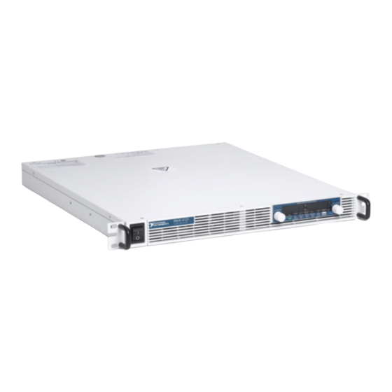
RMX Programmable Power Supplies
RMX-4120/4121/4122/4123/4124/4125/4126/4127
About the RMX Safety Information & Installation Guide
This guide is intended for users of the Regulated DC Power Supply and their instructors.
It is assumed that the reader has knowledge about electrical safety standards and the electrical
aspects of regulated DC power supplies.
Safety Guidelines
Indicates general danger, warning, or caution. When this symbol is marked on the
product, see the relevant section in the operation manual.
Indicates a location whose surface can become hot.
Protective conductor terminal.
Chassis (frame) terminal.
On (supply).
Off (supply).
Installation and Preparation
This section describes how to turn on an RMX programmable power supply, what kind of load
cables to use, and how to connect cables to the output connectors.
Protection provided by this equipment may be impaired if it is used in a
Note
manner not described in the manual.
Advertisement
Table of Contents

Summary of Contents for National Instruments RMX-4120
-
Page 1: Safety Guidelines
SAFETY INFORMATION & INSTALLATION GUIDE RMX Programmable Power Supplies RMX-4120/4121/4122/4123/4124/4125/4126/4127 About the RMX Safety Information & Installation Guide This guide is intended for users of the Regulated DC Power Supply and their instructors. It is assumed that the reader has knowledge about electrical safety standards and the electrical aspects of regulated DC power supplies. -
Page 2: Connecting The Power Cord
The product is grounded through the power cord ground wire. Connect the protective conductor terminal to earth ground. RMX-4120/4121/4122/4123 (750 W Models) Necessary Cable • North America—Extra Hard Usage Cord, min. 300 V, 60 C, 14 AWG, 3 Conductor cord, 3 m or less with a NEMA 5-15P to C14. -
Page 3: Switchboard Breaker Requirements
Indicate that the breaker is dedicated for use with this product and that it is used to disconnect the product from the AC power line. RMX Programmable Power Supplies Safety Information & Installation Guide | © National Instruments | 3... -
Page 4: Connection Procedure
Figure 1. Switchboard Diagram Breaker indication example For the RMX-4125 only 30 A RMX-4125 Switchboard dedicated breaker RMX-4125 Power cord Connection Procedure Check that the AC power line meets the nominal input rating of the product. The product can receive a nominal line voltage in the range of 100 VAC to 240 VAC at 50 Hz or 60 Hz. Check that the POWER switch is turned off. - Page 5 Attach an appropriate crimping terminal to the switchboard end of the power cord. Turn off the switchboard breaker. Connect the L, N, and (GND) wires of the power cord to the matching terminals on the switchboard. RMX Programmable Power Supplies Safety Information & Installation Guide | © National Instruments | 5...
-
Page 6: Turning The Power Switch On
Turning the Power On Turning the POWER Switch On Risk of electric shock. Regardless of whether load cables are connected to Caution the output terminals, be sure to attach the OUTPUT terminal cover before turning the POWER switch on. Load Cables Risk of fire. - Page 7 Connect the positive cable to the positive output terminal and the negative cable to the negative output terminal. The orientation of the crimping terminals will vary depending on the wire diameter of the load cables used. RMX Programmable Power Supplies Safety Information & Installation Guide | © National Instruments | 7...
- Page 8 Figure 7. Connection Using M8 Bolt Set for RMX-4120/4121/4124/4125 Crimping terminal Bolt (M8) Washer Spring washer Attach the cable to the inner side of the crimping terminal. Figure 8. Connection Using M5 Bolt Set for RMX-4122/4123/4126/4127 Crimping terminal Bolt (M5)
-
Page 9: Attaching The Output Terminal Cover
Align the tabs of the top half of the OUTPUT terminal cover with those of the bottom half. Align the tabs of the OUTPUT terminal cover according to the load cable diameter. RMX Programmable Power Supplies Safety Information & Installation Guide | © National Instruments | 9... - Page 10 Figure 10. Aligning Both Halves of the OUTPUT Terminal Cover For thin load cables Align the protrusion of Cover hole diameter: the top half of the cover Top half of the cover Up to 10 mm with the middle section of the protrusion of the bottom half of the cover.
-
Page 11: Specifications
Operating temperature ......0 to 50 °C (32 to 122 °F) Operating humidity........20 to 85% rh (no condensation) Altitude ............. Up to 2,000 m Pollution degree ........2 With the rated load. RMX Programmable Power Supplies Safety Information & Installation Guide | © National Instruments | 11... -
Page 12: Electromagnetic Compatibility
Safety This product is designed to meet the requirements of the following standards of safety for electrical equipment for measurement, control, and laboratory use: • IEC/EN 61010-1 • UL 61010-1 • CSA C22.2 No. 61010-1 For safety certifications, refer to the product label or the Online Product Note Certification... -
Page 13: Online Product Certification
2002/96/EC on Waste and Electronic Equipment, visit ni.com/environment/ weee National Instruments (RoHS) National Instruments RoHS ni.com/ (For information about China RoHS compliance, environment/rohs_china go to ni.com/environment/rohs_china RMX Programmable Power Supplies Safety Information & Installation Guide | © National Instruments | 13... -
Page 14: Worldwide Support And Services
Worldwide Support and Services The NI website is your complete resource for technical support. At you have ni.com/support access to everything from troubleshooting and application development self-help resources to email and phone assistance from NI Application Engineers. Visit for NI Factory Installation Services, repairs, extended warranty, and ni.com/services other services. - Page 15 For patents covering NI products/technology, refer to the appropriate location: Help»Patents in your software, the patents.txt file on your media, or the National Instruments Patents Notice at ni.com/patents. You can find information about end-user license agreements (EULAs) and third-party legal notices in the readme file for your NI product.


Need help?
Do you have a question about the RMX-4120 and is the answer not in the manual?
Questions and answers