Invacare HomeFill II Service Manual
Hide thumbs
Also See for HomeFill II:
- Operator's manual (248 pages) ,
- User manual (220 pages) ,
- Operator's manual (148 pages)
Table of Contents
Advertisement
Service Manual
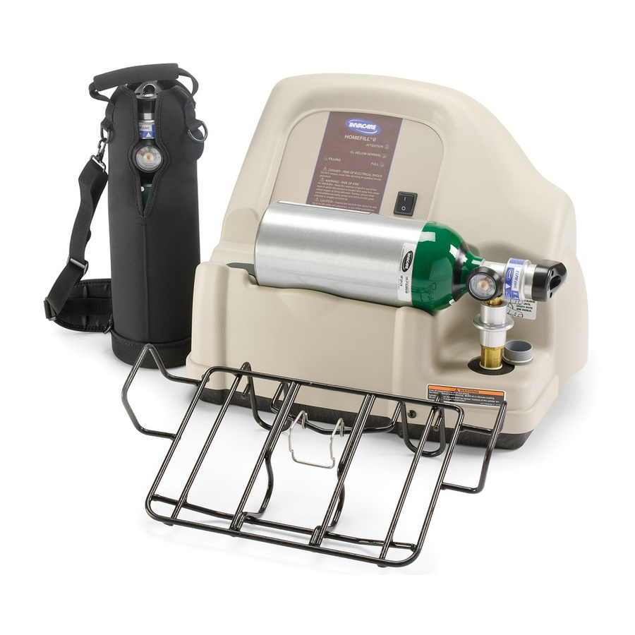
HomeFill™II Compressor
NOTE: Compressor shown without cylinder attached.
NOT FOR GENERAL DISTRIBUTION - DO NOT COPY
DEALER: Keep this manual. The
procedures in this manual MUST be
performed by a qualified technician.
For more information regarding
Invacare products, parts, and services,
please visit www.invacare.com
Advertisement
Table of Contents

Related Manuals for Invacare HomeFill II


Summary of Contents for Invacare HomeFill II
- Page 1 NOTE: Compressor shown without cylinder attached. NOT FOR GENERAL DISTRIBUTION - DO NOT COPY DEALER: Keep this manual. The procedures in this manual MUST be performed by a qualified technician. For more information regarding Invacare products, parts, and services, please visit www.invacare.com...
-
Page 2: Reference Documents
Refer to the following table for part numbers of additional documents which are referenced in this manual. MANUAL PART NUMBER HomeFill II Compressor Operator’s Manual 1100873 Platinum Concentrator Owner’s Manual 1118353 Platinum Concentrator Service Manual 1110538 NOTE: Updated versions of this manual are available on www.invacare.com. HomeFill™II Compressor Part No 1141487... -
Page 3: Table Of Contents
TABLE OF CONTENTS TABLE OF CONTENTS REFERENCE DOCUMENTS ..............2 SPECIAL NOTES ................6 TYPICAL PRODUCT PARAMETERS ............ 7 LABEL LOCATION ................8 SECTION 1—GENERAL GUIDELINES ........... 9 Operating Information..........................9 Handling ..............................10 Maintenance ...............................10 Radio Frequency Interference .......................10 To Reduce the Risk of Burns, Electrocution, Fire or Injury to Persons........10 SECTION 2—... - Page 4 TABLE OF CONTENTS TABLE OF CONTENTS SECTION 6—PANEL ASSEMBLY ............24 Replacing Exhaust Fan..........................24 Removing/Installing Control Panel......................25 Installing ..............................25 Testing/Replacing the Power Switch ....................27 Replacing Circuit Board ..........................28 Replacing/Rebuilding Compressor Assembly ..................29 Replacing Accumulator Assembly......................29 Units manufactured before 10/03/05 ....................29 Units manufactured after 10/02/05....................30 Installing Accumulator Assembly......................30 SECTION 7—BASE COMPONENTS ............
- Page 5 Indicator Light Explanation........................47 Troubleshooting............................47 Cylinder Fill Times ...........................49 Leak Test ..............................49 Cylinder Fill Test ............................50 HomeFill II 2000 psi Switch/P.C.B. Shut Down Test................53 SECTION 10—MAINTENANCE ............55 Cleaning/Replacing the Cabinet Filter....................55 Cleaning Cabinet............................55 Verification Process - Invacare HomeFill II Compressor..............56 Function Test.............................56...
-
Page 6: Special Notes
WARNING Invacare products are specifically designed and manufactured for use in conjunction with Invacare accessories. Accessories designed by other manufacturers have not been tested by Invacare and are not recommended for use with Invacare products. HomeFill™II Compressor Part No 1141487... -
Page 7: Typical Product Parameters
TYPICAL PRODUCT PARAMETERS TYPICAL PRODUCT PARAMETERS REGULATORY LISTING: Double Insulated Product ETL Certified Complying with UL1431, UL1097 (US) ETL Certified Complying with CAN/CSA C22.2 No. 68 (Canada) OPERATING TEMPERATURE: 50 to 95° F (10 to 35° C) @ 20 to 60% non-condensing humidity STORAGE TEMPERATURE: -10 to 150°... -
Page 8: Label Location
LABEL LOCATION LABEL LOCATION WARNING Keep all connections free of oil and grease to avoid violent ignition. See Owner's Manual before cleaning. P/N 1075220 Rev C - 10/04 WARNING DO NOT REMOVE UNIT COVER This unit contains moving and high pressure P/N 1075221 components. -
Page 9: Section 1-General Guidelines
These solutions may be flammable and cause injury. The HomeFill II is equipped with a High Pressure Relief Valve to ensure the user’s safety. When activated, this safety feature will make an extremely loud noise. If this noise occurs, turn the unit Off. -
Page 10: Handling
Storage in areas such as this can result in bursting of the bottle or fire. Maintenance The HomeFill II compressor was specifically designed to minimize routine preventive maintenance. Only professionals of the healthcare field or persons fully conversant with this process, such as authorized or factory trained personnel, should perform preventive maintenance or performance adjustments on the compressor. - Page 11 The compressor is intended to be used only as an oxygen supplement as described in the Owner's Manual. Invacare products are specifically designed and manufactured for use in conjunction with Invacare accessories. Accessories designed by other manufacturers have not been tested by Invacare and are not recommended for use with Invacare products.
-
Page 12: Section 2- Concentrator Verification And Maintenance
5. Turn the concentrator flow rate down to 3 L/min. 6. Connect the test concentrator to the HomeFill II compressor to be tested. Refer to Connecting the Compressor to the Concentrator on page 12. 7. Test the HomeFill II compressor. Refer to Troubleshooting/Cylinder Fill Times on page 47. - Page 13 SECTION 2—CONCENTRATOR VERIFICATION AND MAINTENANCE NOTE: The metal tabs on the concentrator outlet fitting and the compressor inlet fitting will pop out with an audible “click” when the end of the interconnect hose is properly installed (Detail “C”). 3. For models that DO NOT have coiled tubing, loop any excess interconnect hose and secure to the back of the concentrator with the fastening straps.
-
Page 14: Section 3-Checklist And Cylinder Inspection
SECTION 3—CHECKLIST AND CYLINDER INSPECTION Compressor Operation Checklist Each time the HomeFill II Compressor is used to fill a cylinder, complete the following checklist: Ensure the concentrator has been on for at least 30 minutes. Perform the prefill inspection on the cylinder. -
Page 15: External Examination
If fire or thermal damage is found, replace the cylinder. 3. Inspect the Invacare valve for the following and replace if found: • Debris, oil or grease •... -
Page 16: Section 4-Compressor Operation
3. Remove the cylinder and connector fillport covers (if present). CAUTION DO NOT connect the outlet (cannula) connection to the HomeFill II unit. Otherwise, the conserving cylinder will not work properly. NOTE: On older models, the green dots do not exist. - Page 17 SECTION 4—COMPRESSOR OPERATION PUSH Outer Ring (Sleeve) Connector Fillport DOWN GREEN Dots BEFORE COUPLING CYLINDER, PUSH DOWN ON SLEEVE UNTIL GREEN DOTS ARE VISIBLE. FIGURE 4.1 Resetting Connector Fillport 5. Grasp the cylinder/regulator assembly in the area behind the cylinder gauge in FIGURE 4.2 on page 18.
-
Page 18: Disconnecting Cylinder From Compressor
FIGURE 4.2 Connecting the Cylinder to the Compressor Disconnecting Cylinder From Compressor WARNING DO NOT modify any connections on the HomeFill II compressor. NEVER use tools of any kind to connect/disconnect the cylinder and the compressor. Otherwise, severe injury and/or damage may occur. -
Page 19: Turning The Compressor On
SECTION 4—COMPRESSOR OPERATION 1. Press the compressor power switch to the Off (O) position. 2. Grasp the cylinder/regulator assembly in the area behind the cylinder gauge. 3. With the other hand, grasp the outer ring (sleeve) of the connector fillport and push down. - Page 20 SECTION 4—COMPRESSOR OPERATION 5. Examine the control panel. The following sequence of events should occur: A. 0-3 minutes - The WAIT (YELLOW) light will be lit while the compressor warms B. After three minutes - The FILLING (GREEN) light will be on while the cylinder is filling.
-
Page 21: Section 5-Cabinet Assembly
SECTION 5—CABINET ASSEMBLY SECTION 5—CABINET ASSEMBLY Removing/Installing the Cabinet DANGER To prevent electrical shock, ALWAYS disconnect HomeFill II from electrical outlet before servicing. NOTE: For this procedure, refer to FIGURE 5.1. Tools required for this procedure are: • Phillips screwdriver. -
Page 22: Removing/Installing The Cabinet Filter Grid
SECTION 5—CABINET ASSEMBLY Removing/Installing the Cabinet Filter Grid NOTE: For this procedure, refer to FIGURE 5.2. Tools required for this procedure are: Flat head screwdriver and .09 drill bit Removing 1. Remove the cabinet. Refer to Removing/Installing the Cabinet on page 21. 2. -
Page 23: Replacing Non-Skid Adhesive Back Pad
SECTION 5—CABINET ASSEMBLY Replacing Non-Skid Adhesive Back Pad NOTE: For this procedure, refer to FIGURE 5.3. 1. Peel the existing pad from the cabinet and discard. 2. Peel the backing from the new pad. 3. Attach the new pad to the cabinet. FIGURE 5.3 Replacing Non-Skid Adhesive Back Pad Replacing Foam Gasket... -
Page 24: Section 6-Panel Assembly
SECTION 6—PANEL ASSEMBLY SECTION 6—PANEL ASSEMBLY Replacing Exhaust Fan NOTE: For this procedure, refer to FIGURE 6.1. Tools required for this procedure are: • Phillips Screwdriver • Torque Wrench 1. Remove the cabinet. Refer to Removing/Installing the Cabinet on page 21. 2. -
Page 25: Removing/Installing Control Panel
SECTION 6—PANEL ASSEMBLY Removing/Installing Control Panel NOTE: For this procedure, refer to FIGURE 6.2. Tools required for this procedure are: • Phillips Screwdriver 1. Remove the cabinet. Refer to Removing/Installing the Cabinet on page 21. 2. Remove the two mounting screws securing the top of the control panel (Detail “A”). 3. - Page 26 SECTION 6—PANEL ASSEMBLY DETAIL “A” Mounting Control Panel Screws Base Assembly Mounting Screws CAUTION DO NOT disconnect Opaque Oxygen the opaque oxygen Sensor Sensor Tube sensor tube from the sensor. Wiring Harness Connection Power Switch Circuit Board Wire Connectors Wiring Harness Wiring Harness Connection Connection...
-
Page 27: Testing/Replacing The Power Switch
SECTION 6—PANEL ASSEMBLY Testing/Replacing the Power Switch NOTE: For this procedure, refer to FIGURE 6.3 on page 27. Tools required for this procedure are: • Ohmmeter 1. Remove the cabinet. Refer to Removing/Installing the Cabinet on page 21. 2. Remove the control panel. Refer to Removing/Installing Control Panel on page 25. 3. -
Page 28: Replacing Circuit Board
SECTION 6—PANEL ASSEMBLY Replacing Circuit Board CAUTION Before handling any circuit boards, you need to be properly grounded to prevent static damage to the components of the circuit board. A static strap MUST be worn and properly grounded using an alligator clip. Electrical conduit or a water pipe is normally sufficient when a known good ground is not available. -
Page 29: Replacing/Rebuilding Compressor Assembly
SECTION 6—PANEL ASSEMBLY Replacing/Rebuilding Compressor Assembly There are no serviceable parts in the compressor assembly. The HomeFill II MUST be returned to Invacare for service. Replacing Accumulator Assembly DANGER To prevent electrical shock, ALWAYS disconnect compressor from electrical outlet before servicing. -
Page 30: Units Manufactured After 10/02/05
SECTION 6—PANEL ASSEMBLY Oxygen Hose Fitting Main Bracket Fitting Tie Wrap Main Bracket Mounting Screw Accumulator Assembly FIGURE 6.5 Replacing Accumulator Assembly - Units manufactured before 10/03/05 Units manufactured after 10/02/05 NOTE: For this procedure, refer to FIGURE 6.6 on page 31. Removing Accumulator Assembly 1. - Page 31 SECTION 6—PANEL ASSEMBLY Rear Fitting Main Bracket Tie-Wrap Oxygen Hose Mounting Screw Oxygen Hose Tie-Wrap Front Fitting Accumulator Assembly FIGURE 6.6 Replacing Accumulator Assembly - Units manufactured after 10/02/05 Part No 1141487 HomeFill™II Compressor...
-
Page 32: Section 7-Base Components
SECTION 7—BASE COMPONENTS SECTION 7—BASE COMPONENTS Replacing Fuse NOTE: For this procedure, refer to FIGURE 7.1. 1. Unplug the power cord from the electrical outlet. 2. Remove the power cord from the power inlet on the compressor base. 3. Pull out the fuse drawer at the bottom of the power inlet. 4. -
Page 33: Removing/Installing The Power Inlet
SECTION 7—BASE COMPONENTS Removing/Installing the Power Inlet NOTE: For this procedure, refer to FIGURE 7.2. Tools required for this procedure are: • Phillips screwdriver, • Torque Wrench Removing 1. Remove the cabinet. Refer to Removing/Installing the Cabinet on page 21. 2. -
Page 34: Replacing Hour Meter
SECTION 7—BASE COMPONENTS Replacing Hour Meter NOTE: For this procedure, refer to FIGURE 7.3 on page 34. 1. Remove the cabinet. Refer to Removing/Installing the Cabinet on page 21. 2. Note the orientation of the two wire connectors before removing. 3. -
Page 35: Replacing Transformer
SECTION 7—BASE COMPONENTS CAUTION Be careful not to cut the tubing when performing the following step. 2. Using the side cutters, cut the tie-wrap securing the tubing to the O connector. 3. Remove the tubing from the O connector. 4. Using a 5/8-inch wrench, remove the locknut securing the connector to the base. 5. -
Page 36: Testing/Replacing Capacitor
SECTION 7—BASE COMPONENTS 8. Connect the four wire connectors to the transformer in the orientation (for colors and sizes) noted previously. 9. Install the cabinet. Refer to Removing/Installing the Cabinet on page 21. Transformer Mounting Screw Wire Connector Mounting Screw Base Wire Connector FIGURE 7.5 Replacing Transformer... -
Page 37: Replacing Capacitor
SECTION 7—BASE COMPONENTS Replacing Capacitor WARNING The capacitor is an electrical storage device that stores an electric charge. ALWAYS discharge the capacitor before testing or handling. Failure to discharge the capacitor may result in bodily harm and/or damage to test equipment. NOTE: For this procedure, refer to FIGURE 7.6. -
Page 38: Removing Connector Fillport Dust Cover And Lanyard - Units Manufactured Before 10/03/2005
SECTION 7—BASE COMPONENTS Removing Connector Fillport Dust Cover and Lanyard - Units Manufactured Before 10/03/2005 DANGER To prevent electrical shock, ALWAYS disconnect compressor from electrical outlet before servicing. Removing NOTE: For this procedure, refer to FIGURE 7.7 on page 39. Tools required for this procedure are: •... -
Page 39: Removing/Installing Connector Fillport Dust Cover And Lanyard - Units Manufactured After 10/02/2005
SECTION 7—BASE COMPONENTS Dust Cover NOTE: Lanyard not shown. Connector Fillport Shaft Locknut Washer Washer Flange Mounting Screw Quick-Release Pin Connecting Flange to Base Washers Locknut for Locknut Oxygen Line FIGURE 7.7 Removing Connector Fillport Dust Cover and Lanyard - Units Manufactured Before 10/03/2005 Removing/Installing Connector Fillport Dust Cover and Lanyard - Units Manufactured After 10/02/2005... -
Page 40: High Pressure Switch Replacement
SECTION 7—BASE COMPONENTS 2. Secure the flange to the bottom of the connector fillport with the three mounting screws. Securely Tighten. 3. Secure the two washers and connector fillport to the compressor with the quick release pin. 4. Secure the flange to the base assembly with a mounting screw. Securely tighten. 5. -
Page 41: Replacing Burst Disk Fitting
SECTION 7—BASE COMPONENTS CAUTION Gloves must be worn during the re-installation process to prevent oil from skin contacting the high-pressure switch. 7. Using a 1-1/8” crows foot, install the high- pressure switch. Torque the high pressure switch to 50 -55 inch pounds. 8. - Page 42 SECTION 7—BASE COMPONENTS High Pressure Switch Burst Disk Fitting FIGURE 7.9 High Pressure Switch Replacement/Replacing Burst Disk Fitting HomeFill™II Compressor Part No 1141487...
-
Page 43: Section 8-Wiring Assemblies
3. Remove the two mounting screws that secure the transformer to the base (Detail “A”). 4. Disconnect the connector from the circuit board (Detail “B”). 5. Remove the transformer assembly wire harness from the HomeFill II compressor. Part No 1141487... -
Page 44: Replacing Bleed Resistor Assemblies
SECTION 8—WIRING ASSEMBLIES 6. Secure the new transformer to the base with the two mounting screws (Detail “A”). Securely tighten 7. Connect the transformer assembly wire harness to the circuit board (Detail “B”). 8. Install the control panel. Refer to Removing/Installing Control Panel on page 25. 9. -
Page 45: Replacing Hfii Assembly Wire Harness
SECTION 8—WIRING ASSEMBLIES DETAIL “A” DETAIL “B” Bleed Resistor Bleed Resistor Assembly 2 Assembly 1 Motor Assembly Power Inlet Grounding Clip Bleed Resistor Assembly 1 DETAIL “C” Control Panel Bleed Resistor Assembly 2 FIGURE 8.3 Replacing Bleed Resistor Assemblies Replacing HFII Assembly Wire Harness NOTE: For this procedure, refer to FIGURE 8.4 on page 46. - Page 46 SECTION 8—WIRING ASSEMBLIES 7. Disconnect the following connectors: A. Two connectors to the high pressure switch (Detail “B”). B. Two connectors to the circuit board (Detail “C”). C. Two connectors to the On/Off switch (Detail “C”). D. Connector to the motor (Detail “D”). 8.
-
Page 47: Section 9-Troubleshooting/Cylinder Fill Times
2. Check that power cord is properly plugged into compressor and wall outlet. 3. Check the fuse on the compressor. If bad, replace. 4. Turn the compressor On. 5. If performing STEPS 1-4 does not cause any indicator lights to come on, contact Invacare for service. Part No 1141487 HomeFill™II Compressor... - Page 48 5. Check the concentrator liter flow setting is at three L/min. or less. If necessary, adjust the liter flow setting (refer to the HomeFill II owner’s manual). If the GREEN filling light does not go Off, the compressor and/or concentrator may need service.
-
Page 49: Cylinder Fill Times
• High Pressure Gauge • Leak Tek 50/50 Mix • Flashlight 1. Plug HomeFill II into an electrical outlet. 2. Attach a high pressure gauge to the fill line disconnect. 3. Attach the oxygen concentrator line to the inlet fitting. Refer to Concentrator Verification and Maintenance on page 12. -
Page 50: Cylinder Fill Test
14. Bleed the pressure down to 1000 ± 200 psi and repeat STEP 13 to confirm. Cylinder Fill Test NOTE: For this procedure, refer to FIGURE 9.2 on page 52. The following procedure describes the cylinder fill test process for the HomeFill II. Tools and Supplies Needed: • Timer. See Figure 9.1. - Page 51 Perform leak checks on the HomeFill II compressor throughout testing. Perform periodic maintenance on test concentrator to ensure consistent results. 1. Place an empty M6 cylinder into the connector fillport on the HomeFill II. Refer to Connecting the Cylinder to the Compressor on page 16.
- Page 52 90%, the cylinder is in the “0” position, and there are no leaks in the HomeFill II unit. Refer to Leak Test on page 49. 10. Remove the full cylinder from the HomeFill II and bleed the pressure out completely. 11. After the first successful fill, repeat STEP 5 to STEP 9.
-
Page 53: Homefill Ii 2000 Psi Switch/P.c.b. Shut Down Test
4. Attach HomeFill II to your test concentrator, and set flow to 3 L/min (not shown). 5. After three minutes the HomeFill II will start to fill the test gauge, the needle will move off of zero and begin to climb steadily. - Page 54 SECTION 9—TROUBLESHOOTING/CYLINDER FILL TIMES HomeFill II Connector Fillport 2000 psi gauge FIGURE 9.3 HomeFill II 2000 psi Switch/P.C.B. Shut Down Test HomeFill™II Compressor Part No 1141487...
-
Page 55: Section 10-Maintenance
SECTION 10—MAINTENANCE SECTION 10—MAINTENANCE Cleaning/Replacing the Cabinet Filter WARNING Unplug the compressor when cleaning. DO NOT operate the compressor without the filter installed. NOTE: For this procedure, refer to FIGURE 10.1. NOTE: All compressors have one filter on the back of the cabinet. NOTE: Perform this procedure at least once a week. -
Page 56: Verification Process - Invacare Homefill Ii Compressor
Clean/Replace the filter (located in back of cabinet – IVC Part # 2000489) NOTE: If any damage is found, return unit to Invacare. If any of the warning labels are missing, please order replacement labels from Invacare. Function Test (procedure... -
Page 57: Verification Process - Invacare Homefill Ii Cylinder
NOTE: All filling times are approximate and may vary with environmental conditions. Verification Process - Invacare HomeFill II Cylinder NOTE: Inspection to be performed upon delivery of unit from Invacare and upon return of unit from rental periods. MODEL No.________________________ SERIAL No._______________________... -
Page 58: Function Test
Function Test (Procedure below) Function Test 1. Make sure the cylinder fill port properly connects to the HomeFill II filling unit. 2. Partially fill the cylinder to check for proper filling operation (15 min). 3. Verify movement on gauge. 4. Check the cylinder for leaks. -
Page 59: Limited Warranty
Invacare warrants the HomeFill II Compressor to be free from defects in materials and workmanship for a period of one (1) year from date of purchase from Invacare or a dealer, with a copy of the seller’s invoice required for coverage under this warranty. - Page 60 LIMITED TO, MODIFICATION THROUGH THE USE OF UNAUTHORIZED PARTS OR ATTACHMENTS) OR TO PRODUCTS DAMAGED BY REASON OF REPAIRS MADE TO ANY COMPONENT WITHOUT THE SPECIFIC CONSENT OF INVACARE CORPORATION OR TO PRODUCTS DAMAGED BY CIRCUMSTANCES BEYOND INVACARE CORPORATION'S CONTROL.
Need help?
Do you have a question about the HomeFill II and is the answer not in the manual?
Questions and answers
why does the unit take over 3 hours to fill a tank. After I send it in for service it only takes 30 min or so. The more I use it the slower it gets.
The Invacare HomeFill II takes over 3 hours to fill a tank after use because the filling process depends on the system's condition and prior usage. After regular use, the system may take longer due to factors such as residual pressure, environmental conditions, or variations in oxygen supply. In contrast, after service, the system is likely optimized, cleaned, and any potential restrictions are addressed, allowing it to operate at peak efficiency and fill a tank in about 30 minutes.
This answer is automatically generated