
Related Manuals for Kikusui TOS6200A


Summary of Contents for Kikusui TOS6200A
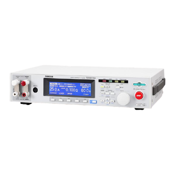
- Page 1 Part No. IB028661 Mar. 2015 USER’S MANUAL EARTH CONTINUITY TESTER TOS6200A TOS6210...
- Page 2 If you find any misplaced or missing pages in this manual, it will be replaced. If the manual gets lost or soiled, a new copy can be provided for a fee. In either case, please contact your Kikusui agent or distribu- tor, and provide the “Kikusui Part No.”...
-
Page 3: Safety Symbols
When this symbol is marked on the product, see the relevant sections in this manual. Protective conductor terminal. Chassis (frame) terminal. On (supply) Off (supply) In position of a bi-stable push control Out position of a bi-stable push control TOS6200A/6210 Safety Symbols... -
Page 4: Table Of Contents
Panel Memory - - - - - - - - - - - - - - - - - - - - - - - - - - - - - - - - - - - - - - - - 4-24 4.6.1 Storing in the Panel Memory - - - - - - - - - - - - - - - - - - - - - - - - 4-25 Contents TOS6200A/6210... - Page 5 - - - - - - - - - - - - - - - - - - - - - - - - - 6-29 6.3.6 Program-Related Messages - - - - - - - - - - - - - - - - - - - - - - - - - 6-32 TOS6200A/6210 Contents...
- Page 6 Initial Settings of the Memory - - - - - - - - - - - - - - - - - - - - - - - - - - - - - -A-3 Summary of the Safety Standards for Earth Continuity Testing - - - - - - - -A-4 Index ___________________________________________________ I- 1 Contents TOS6200A/6210...
-
Page 7: Chapter 1 General
Chapter 1 General Gives an overview of the tester and describes its features and various options. TOS6200A/6210... -
Page 8: Overview Of The Manual
Overview of the Manual This operation manual is for the TOS6200A/6210 earth continuity tester. ■ Firmware version of products applied This Operation Manual applies to products with version 2.0x firmware installed. The ROM version number is displayed in the opening screen displayed immediately after power is switched ON. -
Page 9: Introduction And Features
IEC, EN, UL, VDE, BS, JIS, and the Electri- cal Appliance and Material Control Law of Japan. The tester must be used under the following conditions: TOS6200A TOS6210 Test current value 3Aac to 30 Aac... - Page 10 • Compact and lightweight A new high-efficiency power supply (achieving a power conversion efficiency of 65%) and large output (TOS6200A: 150 VA, TOS6210: 220 VA) makes possible a tester that is remarkably compact and lightweight, about half the size and weight of our conventional testers.
- Page 11 The tester comes with alligator clip test leads, letting you start testing immedi- ately. • Memo function The tester has a memo function that can store up to 20 characters per line on 3 lines, which can be used to store serial numbers, calibration dates, and/or com- ments. TOS6200A/6210 General...
-
Page 12: Options
STOP switch Used to shut off output voltage or cancel a FAIL status; has the same function as the STOP switch located on the tester. RC01-TOS: RC02-TOS: 200mm(W) x 70mm(H) x 39mm(D) 330mm(W) x 70mm(H) x 39mm(D) General TOS6200A/6210... - Page 13 Maximum rating: LP01-TOS 30 A LP02-TOS 60 A Cable length: Accessory: LOW Test Lead (LP01-TOS/LP02-TOS) 2 m LP01-TOS: LP02-TOS: 28 mm(W) x 45.5 mm(H) x 226 mm(D) 28 mm(W) x 45.5 mm(H) x 226 mm(D) LOW Test Lead TOS6200A/6210 General...
- Page 14 General TOS6200A/6210...
-
Page 15: Chapter 2 Installation And Preparation For Use
Chapter 2 Installation and Preparation for Use Describes the steps from unpacking to installation to preparation required before switching on POWER. TOS6200A/6210... -
Page 16: Unpacking Checks
Upon receiving the product, make sure the package contains the necessary accesso- ries, and that the product has not been damaged during transportation. If any damage or imperfection is found, contact Kikusui distributor/agent. The power cord that is provided varies depending on the destination for the product at the factory-shipment. -
Page 17: Precautions For Installation
• Do not use the rubber strips on the sides as feet. Use of the product in an upright position with a rubber strip at the bottom may cause the product to fall down, resulting in damage to the tester or injury to the user. TOS6200A/6210 Installation and Preparation for Use... -
Page 18: Connecting The Ac Power Cord
3 m or less in length. If obtaining a power cord is difficult, con- tact your Kikusui agent or distributor. • The power cord with a plug can be used to disconnect the product from the AC line in an emergency. -
Page 19: Connecting The Test Leads
2.4.1 Supplied Test Lead TL11-TOS/TL12-TOS Remove the short-circuit bars connecting the OUTPUT and SAMPLING terminals. TOS6200A TOS6210 Take care not to get your finger caught between the output terminals when turning the knobs. Connect the current output line on the crimp terminal side of the test lead (black or white) to the LOW side of the OUTPUT terminals;... - Page 20 WARNING burns or injury resulting from heat generated by contact resistance at the terminals. Connecting example of TOS6200A Connect the alligator clip of the test lead (black or white) to the protec- tive conductor terminal of the DUT. Connect the alligator clip of the test lead (red) to a test point of the DUT.
-
Page 21: Optional Test Probe Lp01-Tos/Lp02-Tos
Tester. Figure shows connections of the TOS6210 with the LP02-TOS. TOS6210 To SAMPLING LOW terminal To OUTPUT LOW terminal To the REMOTE terminal To SAMPLING HIGH terminal To OUTPUT HIGH terminal TOS6200A/6210 Installation and Preparation for Use... -
Page 22: Other Leads
Resistance values with respect to the nominal sectional areas of wires are as follows: Use lead wires within a total lead length of 10 m or less. Nominal Sectional Areas of Wire Resistance Value per Meter 3.5 m 5.5 mm 1.5 m 14 mm Installation and Preparation for Use TOS6200A/6210... -
Page 23: Measurements Using Four Terminals
Two-terminal measurements can be performed with the resistance components (R1, R2) of the leads and the contact resistances (r1 to r4) of the OUTPUT terminals sub- tracted beforehand. For more information, see 4.2.6, "Offset Canceling Function.” TOS6200A/6210 Installation and Preparation for Use... -
Page 24: Connecting To The Dut
■ Testing from the protective conductor terminal on the enclo- sure Connect one of the test leads to the protective conductor terminal of the DUT; con- nect the other test lead to a test point. 2-10 Installation and Preparation for Use TOS6200A/6210... -
Page 25: Preliminary Inspection
Short-circuit the ends of the test leads and test at a specified current to check for abnormalities. • Perform the test with the OUTPUT terminals opened. This test must result in a FAIL judgement. TOS6200A/6210 Installation and Preparation for Use 2-11... - Page 26 2-12 Installation and Preparation for Use TOS6200A/6210...
-
Page 27: Chapter 3 Part Names And Functions
Chapter 3 Part Names and Functions Gives the names and functions of switches, keys, indications, connectors, and other parts on the front and rear panels. TOS6200A/6210... -
Page 28: Front Panel
These current output terminals are used to connect current output wires for testing. CAUTION • The maximum input voltage between the OUTPUT terminals and chassis is 20 Vac/ 20 Vdc or less. Do not apply an external voltage exceeding this limit. Part Names and Functions TOS6200A/6210... - Page 29 For usage of the feet, see 2.2, "Precautions for Installation.” [8] REMOTE This terminal is used to connect an optional remote control box or dedicated test probe. [9] Function keys Provide functions corresponding to the F1 to F5 menus displayed on the LCD. TOS6200A/6210 Part Names and Functions...
- Page 30 Pressing this key with the SHIFT key held down enables test conditions to be stored to memory. The procedure is the same as for recall. • ENTER key Used to accept an entered memory number when recalling panel memory or when saving test conditions to panel memory. Part Names and Functions TOS6200A/6210...
- Page 31 LED to the right of this key lights. [18] Rotary knob In ready status: Used to set test conditions and other parameters displayed on the LCD. During testing: Used to change the test current. TOS6200A/6210 Part Names and Functions...
-
Page 32: Rear Panel
250V LINE VOLTAGE FREQUENCY MODEL FUSE RANGE RANGE UL198G IEC60127 TOS6200A ND00611-5 KIKUSUI ELECTRONICS CORP. 85 -250V 47- 63Hz 6.3A SLOW 6.3A TOS6210 MADE IN JAPAN [20] [19] AC LINE Fig. 3-3 Rear Panel (example of TOS6210) [19] AC LINE This is the connector for AC power cord that supplies power to the tester. - Page 33 • Never use the tester in an upright position. Use of the product with the cord holders serving as feet causes the tester to fall down, which may result in damage to the tester or injury to the user. TOS6200A/6210 Part Names and Functions...
- Page 34 Part Names and Functions TOS6200A/6210...
-
Page 35: Chapter 4 Basic Operation
Chapter 4 Basic Operation Describes basic operations such as setting test conditions and starting a test. TOS6200A/6210... -
Page 36: Turning On The Power
Test time ON/OFF status 50Hz FREQ LOWER OFFSET TIMER 25.0 0.100 60.0 Test time UPPER LOWER Function menus CURRENT LOWER UPPER TIMER Judgment value or measured value Test current value Status of indication of set reference values Basic Operation TOS6200A/6210... -
Page 37: Setting The Test Conditions
Safety Standards for Earth Continuity Testing.” NOTE • “A.4, "Summary of the Safety Standards for Earth Continuity Testing” is a sum- mary of the safety standards. Before performing actual testing, check the test con- ditions match your appropriate safety standard. TOS6200A/6210 Basic Operation... -
Page 38: Test Current
4.2.1 Test Current Set the maximum current value flowing through the DUT as follows: TOS6200A: 3.0 A to 31.0 A TOS6210: 6.0 A to 62.0 A (resolution: 0.1 A) READY MAIN MAIN 50Hz FREQ LOWER OFFSET TIMER 25.0 0.100 60.0... -
Page 39: Test Frequency
LOWER OFFSET TIMER 25.0 2.50 60.0 25.0 0.100 60.0 Press the SHIFT UPPER UPPER and F4 keys FREQ LOWER OFFSET JUDGE TIMER FREQ LOWER OFFSET JUDGE TIMER together. 50/60Hz ON/OFF ON/OFF ON/OFF 50/60Hz ON/OFF ON/OFF ON/OFF SHIFT TOS6200A/6210 Basic Operation... - Page 40 Resistance value-based judgment Set an upper reference value as follows: TOS6200A: 0.001 to 1.200 (resolution: 0.001 ) TOS6210: 0.001 to 0.600 (resolution: 0.001 ) READY MAIN MAIN 50Hz FREQ LOWER OFFSET TIMER 25.0 0.100 60.0 UPPER...
- Page 41 “OVER LOAD” blinks on the LCD during testing. If the output power exceeds a maximum power rating, the power limitation safety function is tripped and protection status occurs. Change the setting referring to 4.10.3, "Overload Protection (OVER LOAD).” TOS6200A/6210 Basic Operation...
-
Page 42: Lower Reference Value
LOWER OFFSET TIMER 25.0 2.50 60.0 25.0 0.100 60.0 Press the SHIFT LOWER LOWER and F4 keys FREQ LOWER OFFSET JUDGE TIMER FREQ LOWER OFFSET JUDGE TIMER together. 50/60Hz ON/OFF ON/OFF ON/OFF 50/60Hz ON/OFF ON/OFF ON/OFF SHIFT Basic Operation TOS6200A/6210... - Page 43 Resistance value-based judgment Set a lower reference value as follows: TOS6200A: 0.001 to 1.200 (resolution: 0.001 ). TOS6210: 0.001 to 0.600 (resolution: 0.001 ). READY MAIN MAIN 50Hz FREQ LOWER OFFSET TIMER 25.0 0.003 60.0 LOWER...
- Page 44 ON, the “READY” indication in the upper right of the LCD changes to blink “UP <= LOW,” informing you that testing cannot begin under the current conditions. In this case, increase the upper reference value or reduce the lower reference value. 4-10 Basic Operation TOS6200A/6210...
-
Page 45: Test Time
Press the F5 (TIMER) key to move the cursor if the cursor is not below ▲▼ the timer (you can also move the cursor using the keys). Use the keys to move the cursor to the desired digit. Use the rotary knob to set the test duration. TOS6200A/6210 Basic Operation 4-11... -
Page 46: Offset Canceling Function
You can also use the keys to move the cursor to the offset function ON/ OFF indicator. With the cursor at the OFFSET indication use the rotary knob to set. Turning the knob clockwise: Turning the knob counterclockwise: OFF 4-12 Basic Operation TOS6200A/6210... - Page 47 “OVER VA” blinks on the LCD. The setting has exceeded the maximum rated output. Test cannot begin under the current conditions. Change the setting referring to “OVER VA” in 4.9.1, "Setting Output out of the Operation Range.” TOS6200A/6210 Basic Operation 4-13...
-
Page 48: Starting And Ending Test
The time indicated after start of the test differs with the timer function set to ON or OFF. When the timer is ON: The time remaining of the set time is indicated. When the timer is OFF: The elapsed test duration is indicated. (Note: When the time exceeds 999 seconds, “999” blinks.) 4-14 Basic Operation TOS6200A/6210... -
Page 49: Ending The Test
The PASS judgment is generally displayed for about 0.2 seconds (default value). You can set the PASS judgment display time in the range 0.2 s to 10.0 s or to HOLD. For information on altering this setting, see 4.4, "System Setup.” TOS6200A/6210 Basic Operation 4-15... - Page 50 To remove a FAIL judgment, press the STOP switch. The measurement result is displayed until you press the STOP switch. In case of FAIL, the test duration indicates the elapsed time regardless of the timer ON/OFF setting. 4-16 Basic Operation TOS6200A/6210...
-
Page 51: System Setup
When PASS HOLD is set to HOLD, the tester retains the PASS judgment until you press the STOP switch. ▲▼ Press the F2 (PASS) key, or use the keys to move the cursor to PASS HOLD. Use the rotary knob to set a hold time for a PASS judgment. TOS6200A/6210 Basic Operation 4-17... - Page 52 FAIL MODE. When is displayed to the left of FAIL MODE, you can also use the rotary knob to enter ON/OFF settings. Turning the knob clockwise: Turning the knob counterclockwise: OFF 4-18 Basic Operation TOS6200A/6210...
- Page 53 • After testing starts, sparking will occur if the probe is separated from the CAUTION DUT and then recontacts it, potentially damaging the DUT or probe. Sep- arate the probe from the DUT only after pressing the STOP switch. TOS6200A/6210 Basic Operation 4-19...
- Page 54 CONTRAST. Use the rotary knob to set contrast. ▲▼ ▲ ▼ You can set contrast with the SHIFT + key combination (pressing the key with the SHIFT key held down) in any screen. 4-20 Basic Operation TOS6200A/6210...
- Page 55 The display can also be switched by pressing the SHIFT and keys together. ▲▼ Use the keys to move the cursor to the position where you wish to enter a comment. Use the rotary knob to select characters. SYSTEM 3 SYSTEM 3 COMMENT < > PREV TOS6200A/6210 Basic Operation 4-21...
-
Page 56: Interface Setup
• The GPIB address set is not effective until the tester is restarted. ▲▼ Press the F1 (GPIB) key, or use the keys to move the cursor to GPIB ADDRESS. Use the rotary knob to set the GPIB address. 4-22 Basic Operation TOS6200A/6210... -
Page 57: Rs-232C Protocol
Select a stop bit from the following two choices: • 1 bit • 2 bit ▲▼ Press the F5 (STOP) key, or use the keys to move the cursor to STOP. Use the rotary knob to select either 1 or 2. TOS6200A/6210 Basic Operation 4-23... -
Page 58: Panel Memory
25.0 0.100 60.0 UPPER CURRENT LOWER UPPER TIMER On shipment from the factory, settings corresponding to a variety of safety standards are written to memory. For these settings, see Appendix A.3, "Initial Settings of the Memory.” 4-24 Basic Operation TOS6200A/6210... -
Page 59: Storing In The Panel Memory
After the conditions are stored, the letters "STO" will change on the LCD to "MEM." MAIN MAIN 04 : IEC60204-1 50Hz FREQ LOWER OFFSET TIMER 10.0 0.100 10.0 UPPER CURRENT LOWER UPPER TIMER TOS6200A/6210 Basic Operation 4-25... -
Page 60: Recalling The Panel Memory
Moving the cursor to another area of the screen before pressing the ENTER key aborts the recall operation. Modifying the test conditions recalled causes the memory number to disappear. It will not be redisplayed even if the original test conditions are restored. 4-26 Basic Operation TOS6200A/6210... -
Page 61: Program
After the START switch is pressed and the test in step 02 is complete, the tester enters the ready status. Replacing END at the end of the program with RET instructs the program to repeat testing from step 00. TOS6200A/6210 Basic Operation 4-27... -
Page 62: Recalling The Program
Use the rotary knob to select the desired characters. You can enter ASCII codes 20H to 7EH as characters (see Appendix A.2). Press the SHIFT and F1 keys together to complete setting a program name. 4-28 Basic Operation TOS6200A/6210... - Page 63 Press the SHIFT + F2 keys toggles between END and RET. END: Ends the program; the program enters ready status at the beginning of the steps. RET: Causes the program to return to the beginning of the steps and repeat the test. TOS6200A/6210 Basic Operation 4-29...
-
Page 64: Running The Program
Program execution is performed in the program screen (AUTO). In the program screen, the cursor cannot be moved to any item other than the pro- gram number. TEST AUTO AUTO 05 : KIKUSUI NAME : --UNTITLED-- 01 MEM00-9.9s 02 MEM00-9.9s 03 MEM00-9.9s 0.020 04 MEM00-9.9s... -
Page 65: Ending The Program
4.7.6 Ending the Program To exit the program mode and return to normal status, press the MAIN key. This turns off the LED for the AUTO key and redisplays the MAIN screen. TOS6200A/6210 Basic Operation 4-31... -
Page 66: Key Lock
LCD Indication in Cause of Invalid Value the Event of Invalid Setting OVER VOLT OVER VA Setting of output out of the operation range OVER RESI Upper reference value lower reference value UP <= LOW 4-32 Basic Operation TOS6200A/6210... -
Page 67: Setting Output Out Of The Operation Range
5.4 V or below. TOS6200A: 3.0 Aac to 31.0 Aac TOS6210: 6.0 Aac to 62.0 Aac The following figures show the operation range of the testers. - Page 68 ) is made, the “READY” indication in the upper right of the LCD changes to blink “OVER VA,” informing you that testing cannot be conducted under the current conditions. TOS6200A (Test current value) x upper reference value (resistance value) > 150 VA Test current value x upper reference value (voltage value) >...
-
Page 69: Upper Reference Value <= Lower Reference Value (Up <= Low)
“OVER RESI,” informing you that testing cannot be conducted under the cur- rent conditions. TOS6200A: Upper reference value (voltage value) / test current value > TOS6210: Upper reference value (voltage value) / test current value > 0.6 OVER RESI... -
Page 70: 4.10 Protection Fuction
Protection Status the Tester to Protection Status Time limit with respect to output OVER HEAT Overheat protection OVER LOAD Overload protection VOLT LIMIT Output voltage limitation SIGNAL I/O ENABLE signal change CURR ERROR Output current error 4-36 Basic Operation TOS6200A/6210... -
Page 71: Time Limitation With Respect To Output (Over Heat)
6210 ger than test time less Continuous out- I 20 Not required put available Time Test time Pause time OVER HEAT MAIN MAIN 50Hz FREQ LOWER OFFSET TIMER 25.0 0.100 UPPER CURRENT LOWER UPPER TIMER TOS6200A/6210 Basic Operation 4-37... -
Page 72: Overheating Protection (Over Heat)
UPPER TIMER For example, when the test current of TOS6200A is 30 A, if the load resistance (including the resistance of the DUT, the test leads, and any other associated items) from the perspective of the output terminals exceeds 0.166 ( 150/30 ), the output power exceeds 150 VA, causing an overload. -
Page 73: Output Voltage Limitation (Volt Limit)
If the product of the test current and a combined resistance from the perspective of the output terminals is closer to 5.6 V, use leads with lower resistance values. Press the STOP switch to cancel output voltage limitation. TOS6200A/6210 Basic Operation 4-39... -
Page 74: Change In Enable Signal (Signal I/O)
UPPER TIMER If the output terminal voltage exceeds 5.6 V due to the connected load, the current will decrease, which may cause the tester to enter protection status. To clear this protection, press the STOP switch. 4-40 Basic Operation TOS6200A/6210... -
Page 75: 4.11 Initialize
Appendix A.3, “Initial Settings of the Memory.” Press the POWER switch with the SHIFT key held when starting the tester. This restores tester settings to factory-set values. (Press the SHIFT key until the charac- ters "KIKUSUI ELECTRONICS CORP." disappear.) ■ Factory-shipped settings TOS6200A... - Page 76 4-42 Basic Operation TOS6200A/6210...
- Page 77 Chapter 5 REMOTE and SIGNAL I/O Describes the REMOTE terminal (for connecting optional equipment) and the SIGNAL I/O connector (for input/output signals). TOS6200A/6210...
- Page 78 This connector is used to connect the optional RC01-TOS or RC02-TOS remote control boxes or the LP01-TOS or LP02-TOS test probe. When you connect an option, the START and STOP switches on the option and those on the front panel are both available. Fig.5-1 REMOTE Terminal REMOTE and SIGNAL I/O TOS6200A/6210...
-
Page 79: Chapter 5 Remote And Signal I/O
To avoid malfunctions caused by noise, use shielded-type D-sub 25-pin connectors and a cable that is 2.5 m or less in length. For information about how to obtain replacement parts, contact your Kikusui agent or distributor. For information about how to use these components, see the OMRON Corporation catalogs. -
Page 80: Signal I/O Connector Specifications
LOWER FAIL START READY PROTECTION Fig. 5-3 SIGNAL I/O Pin Configuration CAUTION • To avoid damage to internal circuits, take care to avoid short circuiting +24 V at pin 24 to the chassis or circuit common. REMOTE and SIGNAL I/O TOS6200A/6210... - Page 81 ON if PROTECTION status arises. START Start signal input terminal. STOP Stop signal input terminal. ENABLE Start signal’s ENABLE signal input terminal. +24V internal power output terminal. Maximum output current is 100 +24 V Circuit common TOS6200A/6210 REMOTE and SIGNAL I/O...
-
Page 82: Starting A Test
START input for the REMOTE terminal is enabled. At the same time, the START switch on the panel are disabled. ENABLE (IN) READY (OUT) 5 ms or more START (IN) 10 ms or more Fig. 5-5 START Signal REMOTE and SIGNAL I/O TOS6200A/6210... -
Page 83: Recalling A Panel Memory And Program
Recalls panel memory 0 Recalls program 0 Recalls panel memory 1 Recalls program 1 Recalls panel memory 2 Recalls program 2 Recalls panel memory 98 Recalls program 98 Recalls panel memory 99 Recalls program 99 TOS6200A/6210 REMOTE and SIGNAL I/O... -
Page 84: Examples Of Use
Example of getting the "L" level of digital signal This example gets the "L" level of digi- tal signal with respect to an output sig- nal. 30 V or less "L" when output signal is produced REMOTE and SIGNAL I/O TOS6200A/6210... -
Page 85: Chapter 6 Gpib And Rs-232C
Describes the device messages used to create a program for remote control of the tester via GPIB or RS-232C. • To avoid electric shocks, always turn off the power supply of the related WARNING equipment when connecting or disconnecting a cable from the interface connector. TOS6200A/6210... -
Page 86: Interface
To use the GPIB interface, set a GPIB address on the tester. To set a GPIB address, see 4.5, “Interface Setup.” GPIB cables are available from Kikusui. Contact Kikusui distributor/agent. GPIB cable 1 m (code: 92080) GPIB cable 2 m (code: 92070) GPIB cable 4 m (code: 92090) 6.1.2... -
Page 87: The Tester
Control of transmission from the tester to the RS-232C terminal Stop temporarily Resume transmission Up to 10 characters The RS-232C terminal must temporarily stop transmission within 10 characters after receiving a DC3. Fig. 6-2 Control of transmission between the RS-232C terminal and the tester TOS6200A/6210 GPIB and RS-232C... -
Page 88: Message And Terminator
A query ends its message with the question mark (?) at the end. Response Messages sent from the device to the controller or another device are responses. A response tells the controller the status of the device or a measured value. GPIB and RS-232C TOS6200A/6210... - Page 89 There are two types such messages: • OK: Normally terminated • ERROR:Abnormality occurring, such as a syntax error Through the use of a SILENT command, it can be specified whether to return an acknowledgment message. TOS6200A/6210 GPIB and RS-232C...
-
Page 90: Terminator
<NR3> It is described in “IEEE Standards 488.2 Standard Digital Interface for Programmable Instrumentation” in detail. This represents a hexadecimal. <HEX> It is described in “IEEE Standards 488.2 Standard Digital Interface for Programmable Instrumentation” in detail. GPIB and RS-232C TOS6200A/6210... -
Page 91: Device Messages
For details on the event status register, see 6.4, "Registers.” Message Query message: *ESR? Response Returns the contents of the event status register to *ESR?. (Example) If Bit 5 of the event status register is set, “32” is returned. TOS6200A/6210 GPIB and RS-232C... - Page 92 Inquiries about the model name and firmware version of the tester. Message Query message: *IDN? Response Returns the model name of the tester to *IDN? in the following manner: KIKUSUI ELECTRONICS CORP., TOS6210, 0, 1.00 Company name Model name Version No. (not used) Serial No.
- Page 93 00H to FFH (default is 80H) Resolution: (Example) DSE #H01 Response Returns the contents of the device status enable register to DSE?. (Example) If Bit 5 of the device status enable register is set, “32” is returned. TOS6200A/6210 GPIB and RS-232C...
- Page 94 For details on the error register, see 6.4, "Registers.” Message Query message: ERR? Response Returns the contents of the error register to ERR?. (Example) If Bit 1 of the error register is set, “2” is returned. 6-10 GPIB and RS-232C TOS6200A/6210...
- Page 95 For details on the protection register, see 6.4, "Registers.” Message Query message: PROT? Response Returns the contents of the protection register to PROT?. (Example) If Bit 2 (OVER LOAD) of the protection register is set, “4” is returned. TOS6200A/6210 GPIB and RS-232C 6-11...
- Page 96 Set value: CR/LF + EOI (default) LF + EOI CR + EOI Response The response terminator currently set is returned to TRM?. (Example) If the response terminator is set at LF+EOI, the message “1” is returned. 6-12 GPIB and RS-232C TOS6200A/6210...
-
Page 97: System-Related Messages
Set value: 1 to 10 (default is 4) Resolution: (Example) BVOL 2 Response Returns the buzzer set volume in response to BVOL?. (Example) When the volume is set to 3 A value of 3 is returned. TOS6200A/6210 GPIB and RS-232C 6-13... - Page 98 This fills blank entries with spaces so that each line has 20 characters, then returns this as the result. (Example) If "KIKUSUI" is entered in the 1st line, no data is entered in the 2nd line, and "123456789ABCDEFGHIJK" is in the 3rd line, the response...
- Page 99 Start double action ON (Example) DAC 0 Response Returns the set value of start double action in response to DAC?. (Example) When the start double action has been set to ON A value of 1 is returned. TOS6200A/6210 GPIB and RS-232C 6-15...
- Page 100 Normal measurement mode (NORMAL) (default) Measurement mode that holds the maxi- mum value Response Returns the measurement mode in response to MMOD?. (Example) When the measurement mode is NORM A value of NORM is returned. 6-16 GPIB and RS-232C TOS6200A/6210...
- Page 101 (Example) When the PASS hold time has been set to 2 seconds A value of 2.0 is returned. (Example) When the PASS hold time has been set to HOLD A value of HOLD is returned. TOS6200A/6210 GPIB and RS-232C 6-17...
-
Page 102: Messages Relating To Test Conditions And Test Execution
Sets the test current of the tester or inquires about its set value. Message Command message: CUR <NR2> Query message: CUR? Program data Set value: TOS6200A 3.0 to 30.0 (default is 3.0) TOS6210 6.0 to 62.0 (default is 6.0) Resolution: Unit: Response Returns the set value of test current in response to CUR?. - Page 103 Returns the ON/OFF status of resistance value-based judgment to RJUD?. (Example) When resistance value-based judgment is ON “1” is returned. NOTE • RJUD ON and VJUD OFF are the same setting. RJUD OFF and VJUD ON are the same setting. TOS6200A/6210 GPIB and RS-232C 6-19...
- Page 104 Message Command message: LOW <NR2>,{0|1|OFF|ON} Query message: LOW? • Program data<NR2>Lower reference value Set value: 0.001 to 1.200 (TOS6200A) (default is 0.001) 0.001 to 0.600 (TOS6210) (default is 0.001) Resolution: 0.001 Unit: • Program data{0|1|OFF|ON}Lower limit judgment function...
- Page 105 ON, the “READY” indication in the upper right of the LCD changes to blink “UP <= LOW,” informing you that testing cannot begin under the current conditions. In this case, increase the upper reference value or reduce the lower reference value. TOS6200A/6210 GPIB and RS-232C 6-21...
- Page 106 Message Command message: UPP <NR2> Query message: UPP? Program data Set value: 0.001 to 1.200 (TOS6200A) (default is 0.001) 0.001 to 0.600 (TOS6210) (default is 0.001) Resolution: 0.001 Unit: Response Returns the upper reference value to UPP?.
- Page 107 “OVER LOAD” blinks on the LCD during testing. If the output power exceeds a maximum power rating, the power limitation safety function is tripped and protection status occurs. Change the setting referring to 4.10.3, "Overload Protection (OVER LOAD).” TOS6200A/6210 GPIB and RS-232C 6-23...
- Page 108 Returns the test time and ON/OFF status for the timer function in response to TIM?. (Example) When the test time is 60 s and the timer function is ON A value of 60.0,1 is returned. 6-24 GPIB and RS-232C TOS6200A/6210...
- Page 109 This command message is valid only in the test conditions set up (MAIN), offset measurement (OFFSET), or program (AUTO) screens. Switch screens using the FUNCTION message. Message Command message: STAR STOP Stops a test or cancels fail, pass (hold) and protection status. Message Command message: STOP TOS6200A/6210 GPIB and RS-232C 6-25...
-
Page 110: Messages Relating To The Tester Status
It returns the current value being measured during a test or the measured current value obtained immediately before when the test was completed. (Example) When the present measured current value is 25.0 A A value of 25.0 is returned. 6-26 GPIB and RS-232C TOS6200A/6210... - Page 111 (Example) When the device status register: TEST and TEST ON (bit 2, 3 are 1), measured resistance value: 0.180 , measured current value: 25.0 A, maximum measured voltage value: 4.55 V, measured resistance value: 4.50 , and elapsed time: 5.0 s A value of 12,0.180,25.0,4.55,4.50,5.0 is returned. TOS6200A/6210 GPIB and RS-232C 6-27...
- Page 112 Message Query message: VDAT? Response Returns the present measured voltage value in response to VDAT? (Example) When the present measured voltage value is 3.50 V A value of 3.50 is returned. 6-28 GPIB and RS-232C TOS6200A/6210...
- Page 113 <offset>, <timer> Query message: MEM? <memory no.> • Program dataSets the memory contents in the following order. Set value Resolu- Parameter Unit tion TOS6200A TOS6210 Memory no. 0 to 99 <NR1> ASCII code, maxi- 20H to 7EH mum number of...
- Page 114 OFF of lower limit judg- 0,OFF ment lower limit judgment ON of lower limit judg- 1,ON ment 0,OFF OFF of offset Offset 1,ON ON of offset 0,OFF OFF of timer Timer 1,ON ON of timer 6-30 GPIB and RS-232C TOS6200A/6210...
- Page 115 Saves the present test conditions to memory. Note that the memory name is not stored. (Memory names at storage destinations will not be changed.) Message Command message: STOR <NR1> Program data Set value: 0 to 99 Resolution: (Example) STOR 5 TOS6200A/6210 GPIB and RS-232C 6-31...
- Page 116 • Program data<program number NR1>, <step number NR1>, <memory number NR1> Set value: 0 to 99 Resolution: • Program data<interval time NR2> Set value: 0 to 9.9 HOLD Sets the interval time to HOLD. Resolution: Unit: 6-32 GPIB and RS-232C TOS6200A/6210...
- Page 117 • Up to 500 steps can be allotted to a program. For example, if 100 steps each are allotted to programs 0 to 4, no steps can be allotted to program 5. (Example) To assign memory number 5 to step between 9 and 10 in program num- ber 1 PIN 1,10,5 TOS6200A/6210 GPIB and RS-232C 6-33...
- Page 118 Sets ON/OFF for the repeat setting, or inquires about its ON/OFF status. (IF RET is set to OFF, END is assigned to the end of the program.) Message Command message: PRET <program number>,{0|1|OFF|ON} Query message: PRET? <program number> 6-34 GPIB and RS-232C TOS6200A/6210...
- Page 119 The total number of steps for programs is limited to 500. To check the total number of steps, get the number of steps for each program with a PTOT? and sum the num- bers of steps. TOS6200A/6210 GPIB and RS-232C 6-35...
-
Page 120: Registers
Read by serial polling Status byte Service request ESB DSB register issued Read using *STB? Service-request enable register (Initial value 70H) Set using *SRE ESB DSB Read using SRE? Fig. 6-3 Structure of status data 6-36 GPIB and RS-232C TOS6200A/6210... - Page 121 Indicates that an invalid device message has been received during testing or while in protection status. Not used in the tester Not used in the tester Not used in the tester Not used in the tester TOS6200A/6210 GPIB and RS-232C 6-37...
- Page 122 *1: Limit based on the maximum rated output TOS6200A: 150 VA TOS6210: 220 VA *2: Time limitation with respect to the output TOS6200A: 15 A for 30 minutes TOS6210: 10 minutes for > 40 A or 30 minutes for > 20 A 6-38 GPIB and RS-232C...
- Page 123 3 Invalid device message Indicates that an invalid device message was generated. 2 Out-of-range error Indicates occurrence of out-of-range error. 1 Data error Indicates occurrence of data error. 0 Syntax error Indicates occurrence of header error. TOS6200A/6210 GPIB and RS-232C 6-39...
-
Page 124: List Of Device Messages
Returns the value of the device status enable register. ✓ ✓ 23 DSR? Returns the value of the device status register. ✓ ✓ 24 ERR? Returns the value of the error register. ✓ ✓ 25 FAIL? Returns the value of the fail register 6-40 GPIB and RS-232C TOS6200A/6210... - Page 125 Returns the value of the invalid setting register. ✗ ✗ 34 LOWER(LOW) 0.001 to 1.200 0.001 OHM Setting for the lower reference value. (TOS6200A) 0.001 to 0.600 (TOS6210) 0|1|OFF|ON ON/OFF setting for the lower limit judgment function. ✓ ✓ 35 LOWER?(LOW?) Returns the value set for the lower reference value.
- Page 126 Recalls a program. ✓ ✓ 57 PRGTOTAL? 0 to 99 Returns the number of steps in the program corre- (PTOT?) sponding to the program number. ✓ ✓ 58 PROTECTION? Returns the value of the protection register. (PROT?) 6-42 GPIB and RS-232C TOS6200A/6210...
- Page 127 72 TRM? Returns a current response message terminator. ✗ ✗ 73 UPPER(UPP) 0.001 to 1.200 0.001 OHM Setting for upper reference value (TOS6200A) 0.001 to 0.600 (TOS6210) ✓ ✓ 74 UPPER?(UPP?) Returns the upper reference value. ✓ ✓ 75 VDATA?(VDAT?) Returns a measured voltage value.
- Page 128 Data Header Function and response data Reso- Set value Unit lution ✗ ✗ 81 VUPPER(VUPP) 0.01 to 5.40 0.01 Sets the upper reference value. ✓ ✓ 82 VUPPER?(VUPP?) Returns the upper reference value. 6-44 GPIB and RS-232C TOS6200A/6210...
-
Page 129: Chapter 7 Maintenance
Chapter 7 Maintenance Explains tester maintenance and inspection of the tester. To maintain high performance for an extended period, perform maintenance and inspect the tester regularly. TOS6200A/6210... -
Page 130: Cleaning
If you find any breaks or cracks, immediately discontinue any use of the tester. To purchase accessories, please contact your Kikusui distributor/agent. ■ AC power cord Check for tears in the cable coating, looseness and fracture of the plug, and break- age of the cable. -
Page 131: Checking And Replacing The Fuse
6.3 A (T) NOTE • UL and IEC standards provide different designations for pre-arcing time-current char- acteristics of fuses. Use a fuse that complies with one or both of these standards. • The supplied fuses comply with both standards. TOS6200A/6210 Maintenance... -
Page 132: Replacing The Cooling Fan And Backup Battery
• Since replacement of the cooling fan or backup battery involves removing WARNING the cover, all such work should be performed by our service personnel. If replacement is necessary, please contact Kikusui distributor/agent. ■ Cooling fan The cooling fan within the tester is rated for a service life of 60,000 hours. -
Page 133: In Case Of Problems
The fan adjusts its rotational rate depending on the tester's internal tem- peratures; if the internal temperatures are sufficiently low, the fan will not run. If "OVER HEAT" appears on the LCD and the fan is not running, the tester is defective. TOS6200A/6210 Maintenance... - Page 134 Maintenance TOS6200A/6210...
-
Page 135: Chapter 8 Specifications
• Warm-up time: 30 minutes • Temperature: 5C to 35C • Humidity: 20 %rh to 80 %rh (no condensation) • “xx% of reading” represents xx% of the meter reading. • “xx% of setting” represents xx% of the set value. TOS6200A/6210... -
Page 136: Basic Performance
Basic Performance Item TOS6200A TOS6210 Output block 3.0 Aac to 31.0 Aac 6.0 Aac to 62.0 Aac (With respect to resistance resulting in (With respect to resistance resulting in Current setting range *1 output power of the maximum rated output power of the maximum rated... -
Page 137: Specifications
Item TOS6200A TOS6210 Pass/fail judgment function (continued) *3 Sampled voltage value-based judg- Window comparator system ment If a voltage value equal to or greater than the upper reference value is detected, a FAIL determination is returned. If a voltage value equal to or less than the lower reference value is detected, a FAIL determination is returned. -
Page 138: Interface And Other Functions
DOUBLE ACTION Allows testing only when the START switch is pressed within a half-second after the STOP switch is released. CONTACT CHECK Enables the tester to detect a current flowing through the output terminals to begin testing. Specifications TOS6200A/6210... - Page 139 Extended listener No functions operable Service request All functions operable Remote local All functions operable Parallel poll No functions operable Device clear All functions operable Device trigger No functions operable Controller No functions operable Electrical interface Open collector TOS6200A/6210 Specifications...
-
Page 140: General Specifications
EN 55011 (Class A*7, Group 1*8) EN 61000-3-2 EN 61000-3-3 Under following conditions 1. Used test leadwire (TL11-TOS for TOS6200A, TL12-TOS for TOS6210) which is supplied. 2. Used the shielded cable which length is less than three meters when the SIG- NAL I/O is used. - Page 141 Item TOS6200A TOS6210 Physical dimensions (maximum) See 8.4, “External Dimensions” Weight Approx. 9 kg (19.84 lbs) Approx. 11 kg (24.25 lbs) Accessories AC power cord 1 piece Test leadwire TL11-TOS 1 set TL12-TOS 1 set Short bar 2 pieces. (These are inserted between the OUTPUT and SAMPLING terminals.)
-
Page 142: External Dimensions
External Dimensions MAX455 (17.91) 430 (16.93) MAX10 (0.39) Unit: mm (inch) Fig. 8-1 TOS6200A external dimensions MAX455 (17.91) 430 (16.93) 10 (0.39) Unit: mm (inch) MAX15 (0.59) Fig. 8-2 TOS6210 external dimensions Specifications TOS6200A/6210... -
Page 143: Appendix
150 VA (TOS6200A)/220 VA (TOS6210), achieving a power conversion effi- ciency of 90%. (3) Output transformer This step-down transformer generates a rated output of 6 V/25 A (TOS6200A)/6 V, 40A (TOS6210), for which the secondary side is approximately 6 V when the pri- mary side is 30 V. -
Page 144: Ascii Codes 20H To 7Eh
REMOTE terminal, SIGNAL I/O connector, GPIB connector, or RS-232C connector. Also handles signal output to and communications with external devices. ASCII Codes 20H to 7EH NOTE • In the tester, 22H“””, 27H“‘”, 2CH“,” and 40H“@” are unavailable. Appendix TOS6200A/6210... -
Page 145: Initial Settings Of The Memory
Test current: The maximum value of the standardized range • Frequency: 60 Hz for UL standard or 50 Hz for other standards • Test duration: The minimum value of the standardized range (1 sec if not speci- fied in the standard) TOS6200A/6210 Appendix... -
Page 146: Summary Of The Safety Standards For Earth Continuity Testing
• Exercise care so that test results are not affected by the contact resistance the flowing current and voltage between a tester's probe and the metal part being tested. drop. • In measurements of resistance, do not include the value for the AC power cord's protective grounding wire. Appendix TOS6200A/6210... - Page 147 1. 25 A (50 Hz or 60 Hz) or 2. 1.5 times the rated device current, whichever is greater. Allowable resistance value 0.1 or less Test time 5 sec to 10 sec Remarks The no-load voltage must be 6 V or less. TOS6200A/6210 Appendix...
- Page 148 Not specified Remarks In measurements of resistance, do The voltage drop should not exceed Continuity should be detected during not include the value for the AC 10 Vd or 10 Vac. earth continuity testing. power cord's protective grounding wire. Appendix TOS6200A/6210...
- Page 149 Allowable resistance value See Remarks. (0.1 or equivalent, provided that the test current is 15 A) Test time Not specified Remarks • The test voltage must be 30 V or less. • The measured voltage drop must be 1.5 V or less. TOS6200A/6210 Appendix...
- Page 150 Appendix TOS6200A/6210...
-
Page 151: Index
LCD 3-3 Ending the test 4-15 Line voltage 2-4 Excerpts from the safety standards A-4 LOCAL / KEYLOCK 3-5 Lower limit judgment 4-8 Lower reference value 4-8 LP01-TOS 1-7 FAIL judgment 4-16 4-30 LP02-TOS 1-7 Fail Mode 4-18 TOS6200A/6210 Index... - Page 152 Test leads 2-5 Program screen 4-28 Test probe 1-7 Protection fuction 4-36 Test time 4-11 Protection status 4-36 Time limitation with respect to output 4-37 Timer 4-11 TL11-TOS 2-2 RC01-TOS 1-6 TL12-TOS 2-5 RC02-TOS 1-6 Turning on the power 4-2 Index TOS6200A/6210...
- Page 153 Unpacking 2-2 UP<=LOW 4-35 Upper reference value 4-5 VOLT LIMIT 4-39 TOS6200A/6210 Index...
- Page 154 KIKUSUI ELECTRONICS CORP. 1-1-3 Higashiyamata, Tsuzuki-ku, Yokohama, 224-0023, Japan Tel: +81-45-593-7570 Fax: +81-45-593-7571 http://www.kikusui.co.jp/en Website...
Need help?
Do you have a question about the TOS6200A and is the answer not in the manual?
Questions and answers