
Related Manuals for ADLINK Technology PCI-8102


Summary of Contents for ADLINK Technology PCI-8102
- Page 1 PCI-8102 Advanced 2-Axis Servo/Stepper Motion Control Card User’s Manual Manual Rev. 2.01 Revision Date: February 26, 2009 Part No: 50-11136-1010 Advance Technologies; Automate the World.
- Page 2 Copyright 2009 ADLINK TECHNOLOGY INC. All Rights Reserved. The information in this document is subject to change without prior notice in order to improve reliability, design, and function and does not represent a commitment on the part of the manufacturer.
- Page 3 Address: 9F, No.166 Jian Yi Road, Chungho City, Taipei County 235, Taiwan Tel: +886-2-8226-5877 Fax: +886-2-8226-5717 Email: service@adlinktech.com Ampro ADLINK Technology Inc. Address: 5215 Hellyer Avenue, #110, San Jose, CA 95138, USA Tel: +1-408-360-0200 Toll Free: +1-800-966-5200 (USA only) Fax: +1-408-360-0222 Email: info@adlinktech.com...
- Page 4 Address: 84 Genting Lane #07-02A, Cityneon Design Centre, Singapore 349584 Tel: +65-6844-2261 Fax: +65-6844-2263 Email: singapore@adlinktech.com ADLINK Technology Singapore Pte Ltd. (Indian Liaison Office) Address: No. 1357, "Anupama", Sri Aurobindo Marg, 9th Cross, JP Nagar Phase I, Bangalore - 560078, India Tel: +91-80-65605817 Fax: +91-80-22443548 Email:...
-
Page 5: Table Of Contents
Programming Library ............6 MotionCreatorPro ............6 Available Terminal Board............. 7 2 Installation ................9 Package Contents ............... 9 PCI-8102 Outline Drawing ..........10 PCI-8102 Hardware Installation......... 11 Hardware Configuration ..........11 PCI Slot Selection ............11 Installation Procedures ..........11 Troubleshooting ............ - Page 6 DSP Based Motion Control Kernel ....... 43 ASIC Based Motion Control Kernel ......43 Compare Table of All Motion Control Types ....44 PCI-8102’s Motion Controller Type ....... 44 Motion Control Modes............45 Coordinate System ............45 Absolute and Relative Position Move ......46 Trapezoidal Speed Profile ..........
- Page 7 Servo ON/OFF Switch ..........72 Servo Ready Signal ............72 Servo Alarm Reset Switch ..........72 Mechanical Switch Interface ..........73 Original or Home Signal ..........73 End-Limit Switch Signal ..........73 Slow Down Switch ............73 Positioning Start switch ..........74 Counter Clear switch ............
- Page 8 Help Menu ..............113 6 Function Library.............. 115 List of Functions............... 116 C/C++ Programming Library ..........123 Initialization ..............124 Pulse Input/Output Configuration........127 Velocity mode motion............130 Single Axis Position Mode ..........133 Linear Interpolated Motion ..........137 Circular Interpolation Motion ..........140 Home Return Mode............
-
Page 9: List Of Figures
List of Figures Figure 1-1: PCI-8102 Block Diagram ........... 2 Figure 1-2: Flow Chart for Building an Application....... 3 Figure 2-1: PCB Layout of the PCI-8102 ........10 List of Figures... - Page 10 List of Figures...
-
Page 11: Introduction
Introduction The PCI-8102 is an advanced 2-axis motion controller card with a PCI interface. It can generate high frequency pulses (6.55MHz) to drive stepper or servomotors. As a motion controller, it can provide 2-axis linear and circular interpolation and continuous interpolation for continuous velocity. -
Page 12: Figure 1-1: Pci-8102 Block Diagram
An on-screen display lists all installed axes information and I/O signal status of the PCI-8102. Windows programming libraries are also provided for C++ com- piler and Visual Basic. Sample programs are provided to illustrate the operations of the functions. -
Page 13: Figure 1-2: Flow Chart For Building An Application
Figure 1-2: Flow Chart for Building an Application Introduction... -
Page 14: Features
1.1 Features The following list summarizes the main features of the PCI-8102 motion control system. 32-bit PCI bus Plug and Play 2 axes of step and direction pulse output for controlling stepping or servomotor Maximum output frequency of 6.55 MPPS... -
Page 15: Specifications
Includes MotionCreatorPro, a Microsoft Windows-based application development software PCI-8102 libraries and utilities for Windows 2000/XP 1.2 Specifications Applicable Motors: Stepping motors AC or DC servomotors with pulse train input servo driv- Performance: Number of controllable axes: 2 Maximum pulse output frequency: 6.55MPPS, linear, trapezoidal, or S-Curve velocity profile drive Internal reference clock: 19.66 MHz... -
Page 16: Supported Software
PCI-8102 Dimension (PCB size): 120mm(L) X 100mm(W) 1.3 Supported Software Programming Library Windows 2000/XP DLLs are provided for the PCI-8102 users. These function libraries are shipped with the board. MotionCreatorPro This Windows-based utility is used to setup cards, motors, and systems. -
Page 17: Available Terminal Board
1.4 Available Terminal Board DIN-68S and DIN-68M-J3A are available for PCI-8102 wiring. DIN-68S is general purposed pin-to-pin terminal board. Users can use this to connect servos and steppers. DIN-68M-J3A is designed for Mitsubishi servo J3A amplifer. Users can user this board to connect Mitsubishi servo J3A and steppers. - Page 18 Introduction...
-
Page 19: Installation
Installation This chapter describes how to install the PCI-8102 series. Please follow these steps below: Check what you have (section 2.1) Check the PCB (section 2.2) Install the hardware (section 2.3) Install the software driver (section 2.4) Understanding the I/O signal connections (chapter 3) and... -
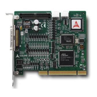
Page 20: Pci-8102 Outline Drawing
2.2 PCI-8102 Outline Drawing 12 1.7 5 119 .9 1 Figure 2-1: PCB Layout of the PCI-8102 Input / Output Signal Connector (68-pin) 16 Digital Input / Output Signals Connector K1 / K2: Simultaneous Start / Stop Connector SW1: DIP switch for card index selection (0-15) -
Page 21: Pci-8102 Hardware Installation
PCI cards in the system. 2.3.2 PCI Slot Selection Your computer system may have both PCI and ISA slots. Do not force the PCI card into a PC/AT slot. The PCI-8102 can be used in any PCI slot. 2.3.3 Installation Procedures 1. -
Page 22: Troubleshooting
2.4 Software Driver Installation PCI-8102: 1. Auto run the ADLINK All-In-One CD. Choose Driver Installation -> Motion Control -> PCI-8102. 2. Follow the procedures of the installer. 3. After setup installation is completed, restart windows. Suggestion: Please download the latest software from ADLINK website if necessary. -
Page 23: P1 Pin Assignments: Main Connector
2.5 P1 Pin Assignments: Main connector P1 is the major connector for the motion control I/O signals. Name Function Axis 0 Name Function Axis 1 Isolated +5V Output Isolated +5V Output EXGND Ext. power ground EXGND Ext. power ground OUT0+ Pulse signal (+) OUT1+ Pulse signal (+) -
Page 24: P2 Pin Assignment: 16 Digital Inputs / 16 Digital Outputs
2.5.1 P2 Pin Assignment: 16 Digital Inputs / 16 Digital Outputs P2 is the second connector for the additional 16 DI/O signals. Name Function Name Function EX_GND -- External Power Ground EX_GND -- External Power Ground Discrete Input Channel 0 Discrete Input Channel 1 Discrete Input Channel 2 Discrete Input Channel 3... - Page 25 1.Digital I/O type -N NPN Sinking Inputt: Inside 8102 R = 330 To CPLD 0.5V Max. DGND PS2805 -N NPN Sinking Output Inside 8102 35V @ 50mA Maximum From CPLD EGND PS2802 Installation...
-
Page 26: K1/K2 Pin Assignments: Simultaneous Start/Stop
2.6 K1/K2 Pin Assignments: Simultaneous Start/ Stop CN4 is for simultaneous start/stop signals for multiple axes or mul- tiple cards. No. Name Function (Axis) PCI Bus power Output (VCC) Simultaneous start signal input/output Simultaneous stop signal input/output PCI Bus power ground Note: +5V and GND pins are provided by the PCI Bus power. -
Page 27: Switch Setting For Card Index
2.8 Switch Setting for card index The SW1 switch is used to set the card index. For example, if you turn 1 to ON and others are OFF. It means the card index as 1. The value is from 0 to 15. Refer to the following table for details. Card ID Switch Setting (ON=1) 0000 0001... - Page 28 Installation...
-
Page 29: Signal Connections
Signal Connections Signal connections of all I/O’s are described in this chapter. Refer to the contents of this chapter before wiring any cables between the 8102 and any motor driver. This chapter contains the following sections: Section 3.1 Pulse Output Signals OUT and DIR Section 3.2 Encoder Feedback Signals EA, EB and EZ Section 3.3 Origin Signal ORG Section 3.4 End-Limit Signals PEL and MEL... -
Page 30: Pulse Output Signals Out And Dir
3.1 Pulse Output Signals OUT and DIR There are 2 axis pulse output signals on the PCI-8102. For each axis, two pairs of OUT and DIR signals are used to transmit the pulse train and to indicate the direction. The OUT and DIR signals can also be programmed as CW and CCW signal pairs. - Page 31 The following wiring diagram is for OUT and DIR signals on the 2 axes. PCI-8102: 26LS31 J8-J11 4.7K OUT+/DIR+ OUT-/DIR- OUT/DIR EXGND NOTE: If the pulse output is set to open collector output mode, OUT- and DIR- are used to transmit OUT signals. The sink current must not exceed 20mA on the OUT- and DIR- pins.
-
Page 32: Encoder Feedback Signals Ea, Eb And Ez
3.2 Encoder Feedback Signals EA, EB and EZ The encoder feedback signals include EA, EB, and EZ. Every axis has six pins for three differential pairs of phase-A (EA), phase-B (EB), and index (EZ) inputs. EA and EB are used for position counting, and EZ is used for zero position indexing. - Page 33 Connection to Line Driver Output To drive the PCI-8102 encoder input, the driver output must pro- vide at least 3.5V across the differential pairs with at least 6mA driving capacity. The grounds of both sides must be tied together. The maximum frequency will be 4Mhz or more depends on wiring distance and signal conditioning.
- Page 34 Inside External Power for Encoder PCI-8102 EA+, EB+, EZ+ Motor Encoder / Driver With Open Collector Output EA-, EB-, EZ- A, B phase signals Index signal For more operation information on the encoder feedback signals, refer to section 4.4. Signal Connections...
-
Page 35: Origin Signal Org
3.3 Origin Signal ORG The origin signals (ORG0~ORG1) are used as input signals for the origin of the mechanism. The following table lists signal names, pin numbers, and axis numbers: P1 Pin No Signal Name Axis # ORG0 ORG1 The input circuit of the ORG signals is shown below. Usually, a limit switch is used to indicate the origin on one axis. -
Page 36: End-Limit Signals Pel And Mel
3.4 End-Limit Signals PEL and MEL There are two end-limit signals PEL and MEL for each axis. PEL indicates the end limit signal is in the plus direction and MEL indi- cates the end limit signal is in the minus direction. The signal names, pin numbers, and axis numbers are shown in the table below: P1 Pin No... -
Page 37: In-Position Signal Inp
3.5 In-Position Signal INP The in-position signal INP from a servo motor driver indicates its deviation error. If there is no deviation error then the servo’s posi- tion indicates zero. The signal names, pin numbers, and axis num- bers are shown in the table below: P1 Pin No Signal Name Axis # INP0... -
Page 38: Alarm Signal Alm
3.6 Alarm Signal ALM The alarm signal ALM is used to indicate the alarm status from the servo driver. The signal names, pin numbers, and axis numbers are shown in the table below: P1 Pin No Signal Name Axis # ALM0 ALM1 The input alarm circuit is shown below. -
Page 39: Deviation Counter Clear Signal Erc
3.7 Deviation Counter Clear Signal ERC The deviation counter clear signal (ERC) is active in the following 4 situations: 1. Home return is complete 2. End-limit switch is active 3. An alarm signal stops OUT and DIR signals 4. An emergency stop command is issued by software (operator) The signal names, pin numbers, and axis numbers are shown in the table below:... -
Page 40: General-Purpose Signal Svon
3.8 General-Purpose Signal SVON The SVON signal can be used as a servomotor-on control or gen- eral purpose output signal. The signal names, pin numbers, and its axis numbers are shown in the following table: P1 Pin No Signal Name Axis # SVON0 SVON1 The output circuit for the SVON signal is shown below:... -
Page 41: General-Purpose Signal Rdy
3.9 General-Purpose Signal RDY The RDY signals can be used as motor driver ready input or gen- eral purpose input signals. The signal names, pin numbers, and axis numbers are shown in the following table: P1 Pin No Signal Name Axis # RDY0 RDY1 The input circuit of RDY signal is shown in the following diagram:... -
Page 42: Position Compare Output Pin: Cmp
3.10 Position Compare Output pin: CMP The 8164 provides 2 comparison output channels, CMP1 and CMP2 used by the first 2 axes, 1 & 2. The comparison output channel will generate a pulse signal when the encoder counter reaches a pre-set value set by the user. The CMP channel is located on P1. -
Page 43: Multi-Functional Input Pin: Ltc/Sd/Pcs/Clr
3.11 Multi-Functional Input Pin: LTC/SD/PCS/CLR The PCI-8102 provides 2 multi-functional input pins. Each of the 2 pins can be configured either as LTC(Latch) or SD(Slow down) or PCS(Target position override) or CLR(Counter clear). To select the pin function, please refer to 6.12. The default value is LTC and the relavant functions are as follows: I16 _8102_select_pin23_input(I16 card_id, U16 Select );... -
Page 44: Pulser Input Signals Pa And Pb
3.12 Pulser Input Signals PA and PB The PCI-8102 can accept input pulser signals through the pins of CN3 listed below. The pulses behaves like an encoder. The sig- nals generate the positioning information, which guides the motor. P1 Pin No Signal Name Axis # P1 Pin No Signal Name Axis #... -
Page 45: Simultaneously Start/Stop Signals Sta And Stp
STA/ STP signals for simultaneous start/stop. If there are two or more PCI-8102 cards, connect the K2 connector on the previous card to K1 connector on the following card. The K1 and K2 connectors on a same PCI-8102 are connected inter- nally. - Page 46 STA and STP pins on the K1 connector of the first PCI-8102 card. Signal Connections...
-
Page 47: General Purpose Ttl Output
3.14 General Purpose TTL Output The PCI-8102 provides 2 general purpose open collector outputs and 4 inputs. The signal names, pin numbers, and axis numbers are shown in the table below: Pin No. Name Function DIN0 Digital IN0 DIN1 Digital IN1... -
Page 48: Additional 16 Digital Input / 16 Digital Output
3.15 Additional 16 Digital Input / 16 Digital Output The PCI-8102 also provides the additional 16 open collector out- puts and 16 digital input. The signal name and pin numbers are shown in the following table: P2 is the second connector for the additional 16 DI/O signals. - Page 49 1.Digital I/O type: -N NPN Sinking Inputt Inside 8102 R = 330 To CPLD 0.5V Max. DGND PS2805 -N NPN Sinking Output Inside 8102 R = 330 To CPLD 0.5V Max. DGND PS2805 Signal Connections...
-
Page 50: Termination Board
With maximum flexibility user should put more effort and care to use DIN-68S to avoid wiring errors. The other termina- tion board can be used for PCI-8102 is DIN-68M-J3A. This termi- nation board is used only for Mitsubishi J3A Servo Motor. For Mitsubishi J2A Servo Motor or other servo motors from different vendors, please use DIN-68S termination board. -
Page 51: Operation Theory
Operation Theory This chapter describes the detail operation of the motion controller card. Contents of the following sections are as follows: Section 4.1 Classifications of Motion Controller Section 4.2 Motion Control Modes Section 4.3 Motor Driver Interface Section 4.4 Mechanical Switch Interface Section 4.5 Counters Section 4.6 Comparaters Section 4.7 Other Motion Functions... -
Page 52: Pulse Type Motion Control Interface
closed loop control algorithm to make it possible. This increased the complexity of motion control and not easy to use for a begin- ner. 4.1.2 Pulse Type Motion Control Interface The second interface of motion and motor control is pulses train type. -
Page 53: Software Real-Time Motion Control Kernel
4.1.4 Software Real-time Motion Control Kernel For motion control kernel, there are three ways to accomplish it. They are DSP-based, ASIC based, and software real-time based. A motion control system needs an absolutely real-time control cycle and the calculation on controller must provide a control data at the same cycle. -
Page 54: Compare Table Of All Motion Control Types
Easy 4.1.8 PCI-8102’s Motion Controller Type The PCI-8102 is an ASIC based, pulse type motion controller. We make this card into three blocks: motion ASIC, PCI card, software motion library. Users can access motion ASIC via our software motion libray under Windows 2000/XP, Linux, and RTX driver. Our software motion linrary provides one-stop-function for controlling motors. -
Page 55: Motion Control Modes
4.2 Motion Control Modes Not like motor control is only for positive or negative moving, motion control make the motors run according to a specific speed profile, path trajectory and synchronous condition with other axes. The following sections describe the motion control modes of this motion controller could be performed. -
Page 56: Absolute And Relative Position Move
coordinate system? If the resolution of external encoder is 10,000 pulses per 1mm and the motor will move 1mm if the motion con- troller send 1,000 pulses, It means that when we want to move 1 mm, we need to send 1,000 pulses to motor driver then we will get the encoder feedback value of 10,000 pulses. -
Page 57: Trapezoidal Speed Profile
4.2.3 Trapezoidal Speed Profile Trapezodial speed profile means the acceleration/deceleration area follows a 1st order linear velocity profile (constant accelera- tion rate). The profile chart is shown as below: MaxVel StrVel StrVel Time Tacc (second) Tdec The area of the velocity profile represents the distance of this motion. -
Page 58: S-Curve And Bell-Curve Speed Profile
4.2.4 S-Curve and Bell-Curve Speed Profile S-curve means the speed profile in accelerate/decelerate area fol- lows a 2nd order curve. It can reduce vibration at the beginning of motor start and stop. In order to speed up the acceleration/decel- eration during motion, we need to insert a linear part into these areas. - Page 59 If VSacc or VSdec=0, it means acceleration or deceleration use pure S-curve without linear part. The Acceleration chart of bell curve is shown below: The S-curve profile motion functions are designed to always pro- duce smooth motion. If the time for acceleration parameters com- bined with the final position don’t allow an axis to reach the maximum velocity (i.e.
-
Page 60: Velocity Mode
The unit of distance or position is pulse internally on the motion controller. The minimum length of distance is one pulse. But in PCI-8102, we provide a floating point function for users to transform a physical length to pulses. Inside our software library, we will keep those distance less than one pulse in register and apply them to the next motion function. -
Page 61: Two Axes Linear Interpolation Position Mode
MaxVel Distance StrVel StrVel Time Tacc (second) Tdec The distance is the area of the V-t diagram of this profile. 4.2.7 Two Axes Linear Interpolation Position Mode “Interpolation between multi-axes” means these axes start simul- taneously, and reach their ending points at the same time. Linear means the ratio of speed of every axis is a constant value. -
Page 62: Two Axes Circular Interpolation Mode
As in the diagram below, 2-axis linear interpolation means to move the XY position from P0 to P1. The 2 axes start and stop simulta- neously, and the path is a straight line. The speed ratio along X-axis and Y-axis is (?X: ?Y), respectively, and the vector speed is: When calling 2-axis linear interpolation functions, the vector speed needs to define the start velocity, StrVel, and maximum velocity,... -
Page 63: Continuous Motion
The motion controller will move to the final point user desired even this point is not on the path of arc. But if the final point is not at the location of the shadow area of the following graph, it will run circu- larly without stopping. - Page 64 ond command to the executing register and the third command to first buffer. Now, the second buffer is empty and user can set the 4th command into 2nd buffer. Normally, if users have enough time to set a new command into 2nd buffer before executing register is finished, the motion can run endlessly.
- Page 65 For 2-axis continuous arc interpolation is the same concept. User can set the speed matched between two command’s speed set- ting. If the INP checking is enabled, the motion will have some delayed between each command in buffers. INP check enabled make the desired point be reached but reduce the smoothing between each command.
-
Page 66: Home Return Mode
4.2.10 Home Return Mode Home return means searching a zero position point on the coordi- nate. Sometimes, users use a ORG, EZ or EL pin as a zero posi- tion on the coordinate. At the beginning of machine power on, the program needs to find a zero point of this machine. - Page 67 Home mode=0: ( ORG Turn ON then reset counter ) Home mode=1: (Twice ORG turn ON then reset counter) Home mode=2: (ORG ON then Slow down to count EZ num- Operation Theory...
- Page 68 bers and reset counter) Home mode=3: (ORG ON then count EZ numbers and reset counter) Home mode=4: (ORG On then reverse to count EZ number Operation Theory...
- Page 69 and reset counter) Home mode=5: (ORG On then reverse to count EZ number and reset counter, not using FA Speed) Home mode=6: (EL On then reverse to leave EL and reset Operation Theory...
- Page 70 counter) Home mode=7: (EL On then reverse to count EZ number and reset counter) Home mode=8: (EL On then reverse to count EZ number and reset counter, not using FA Speed) Home mode=9: (ORG On then reverse to zero position, an Operation Theory...
- Page 71 extension from mode 0) Home mode=10: (ORG On then counter EZ and reverse to zero position, an extension from mode 3) Home mode=11: (ORG On then reverse to counter EZ and Operation Theory...
-
Page 72: Home Search Function
reverse to zero position, an extension from mode 5) Home mode=12: (EL On then reverse to count EZ number and reverse to zero position, an extension from mode 8) 4.2.11 Home Search Function This mode is used to add auto searching function on normal home return mode described in previous section no matter which posi- tion the axis is. -
Page 73: Manual Pulser Function
4.2.12 Manual Pulser Function Manual pulser is a device to generate pulse trains by hand. The pulses are sent to motion controller and re-directed to pulse output pins. The input pulses could be multiplied or divided before send- ing out. The motion controller receives two kinds of pulse trains from man- ual pulser device: CW/CCW and AB phase. -
Page 74: Simultaneous Start Function
4.2.13 Simultaneous Start Function Simultaneous motion means more than one axis can be started by a Simultaneous signal which could be external or internal signals. For external signal, users must set move parameters first for all axes then these axes will wait an extern start/stop command to start or stop. -
Page 75: Position Override Function
4.2.15 Position Override Function Position override means that when users issue a positioning com- mand and want to change its target position during this operation. If the new target position is behind current position when override command is issued, the motor will slow down then reverse to new target position. -
Page 76: Motor Driver Interface
4.3 Motor Driver Interface We provide several dedicated I/Os which can be connected to motor driver directly and have their own functions. Motor drivers have many kinds of I/O pins for external motion controller to use. We classify them to two groups. One is pulse I/O signals including pulse command and encoder interface. - Page 77 be the same as motor driver. The modes vs. signal type of OUT and DIR pins are listed in the table below: Mode Output of OUT pin Output of DIR pin Pulse signal in Pulse signal in Dual pulse output (CW/CCW) plus (or CW) minus (or CCW) direction...
-
Page 78: Pulse Feedback Input Interface
Dual Pulse Output Mode (CW/CCW Mode) In this mode, the waveform of the OUT and DIR pins represent CW (clockwise) and CCW (counter clockwise) pulse output respectively. The numbers of pulse represent distance in pulse. The frequency of the pulse represents speed in pulse per sec- ond. - Page 79 For example, if a rotary encoder has 2000 pulses per rotation, then the counter value read from the position counter will be 8000 pulses per rotation when the AB phase is multiplied by four. If users don’t use encoder for motion controller, the feedback source for this counter must be set as pulse command output or the counter value will always be zero.
-
Page 80: In Position Signal
The following diagram shows the waveform. The index input (EZ) signal is as the zero reference in linear or rotary encoder. The EZ can be used to define the mechanical zero position of the mechanism. The logic of signal must also be set correctly to get corret result. -
Page 81: Servo Alarm Signal
4.3.4 Servo Alarm Signal The alarm signal is an output signal from motor driver. It tells motion controller that there has something error inside servo motor or driver. Once the motion controller receives this signal, the pulses command will stop sending and the status of ALM signal will be ON. -
Page 82: Servo On/Off Switch
speed command will be set. If the error counter is zero, it means that zero motor speed command will be set. At following four situations, the ERC signal will be outputted auto- matically from motion controller to motor driver in order to clear error counter at the same time. -
Page 83: Mechanical Switch Interface
servo driver for users to reset the alarm status.Our motion control- ler provides one general output pin for each axis. Users can use this pin for reseting servo alarm status. 4.4 Mechanical Switch Interface We provide some dedicated input pins for mechanical switches like original switch (ORG), plus and minus end-limit switch (?EL), slow down switch (SD), positioning start switch (PCS), counter latch switch (LTC), emergency stop input (EMG) and counter... -
Page 84: Positioning Start Switch
4.4.4 Positioning Start switch The positioning start switch is used to move a specific position when it is turned on. The function is shown as below. 4.4.5 Counter Clear switch The counter clear switch is an input signal which makes the coun- ters of motion controller to reset. -
Page 85: Counters
4.5 Counters There are four counters for each axis of this motion controller. They are described in this section. Command position counter: counts the number of output pulses Feedback position counter: counts the number of input pulses Position error counter: counts the error between command and feedback pulse numbers. -
Page 86: Command And Feedback Error Counter
could be set from a source of command position for an option when no external encoder inputs. The command output pulses and feedback input pulses will not always be the same ratio in mini-meters. Users must set the ratio if these two pulses are not 1:1. -
Page 87: Comparaters
tion and current motion command’s target position in order to calculate relative pulses of current command then send results into pre-register. Please check if the target position is the same with current command position before continuous motion. Espe- cially after the home function and stop function. 4.6 Comparaters There are 5 counter comparators of each axis. -
Page 88: General Comparator
4.6.3 General Comparator The general comparator let users to choose the source to com- pare. It could be chosen from command, feedback position coun- ter, error counter or general counter. The compare methods could be chosen by equal, greater than or less than with directional or directionless. -
Page 89: Other Motion Functions
ing point right after previous image is captured. It can achieve con- tinuous image capturing by this method. 4.7 Other Motion Functions We provide many other functions on the motion controller. Such as backlash compensation, slip correction, vibration restriction, speed profile calculation and so on. The following sections will describe these functions. -
Page 90: Speed Profile Calculation Function
4.7.3 Speed Profile Calculation Function Our motion function needs several speed parameters from users. Some parameters are conflict in speed profile. For example, if users input a very fast speed profile and a very short distance to motion function, the speed profile is not exist for these parame- ters. -
Page 91: Interrupt Control
_8102_int_control() to enable ir disable the interrupt service. There are three kinds of interrupt sources on PCI-8102. One is motion interrupt source and the other is error interrupt source and another is GPIO interrupt sources. Motion and GPIO interrupt sources can be maskable but error interrupt sources can’t. - Page 92 20~31 The error interrupt sources are non-maskable but the error num- ber of situation could be get from _8102_wait_error_interrupt()’s return code if it is not timeout. Error Interrupt return codes Value Description +Soft Limit is ON and axis is stopped -Soft Limit is ON and axis is stopped Comparator 3 is ON and axis is stopped General Comparator or comparaor 4 is ON and axis is stopped...
- Page 93 GPIO Interrupt Source Bit Settings (1=Enable,0=Disable) Description DI0 falling edge DI1 falling edge DI2 falling edge DI3 falling edge DI0 raising edge DI1 raising edge DI2 raising edge DI3 raising edge Pin23 input interrupt Pin57 input interrupt Pin23/57 interrupt mode selection (0=falling, 1=raising) 11~14 GPIO interrupt switch ( Always=1) The steps for using interrupts:...
-
Page 94: Multiple Card Operation
4.9 Multiple Card Operation The motion controller allows more than one card in one system. Since the motion controller is plug-and-play compatible, the base address and IRQ setting of the card are automatically assigned by the PCI BIOS at the beginning of system booting. Users don’t need and can’t change the resource settings. -
Page 95: Motioncreatorpro
This chapter gives guidelines for establishing a control system and manually testing the PCI-8102 cards to verify correct operation. The MotionCreatorPro software provides a simple yet powerful means to setup, configure, test, and debug a motion con- trol system that uses PCI-8102 cards. - Page 96 3. To duplicate configurations from one system to another, copy 8102.ini and 8102MC.ini into the windows root directory. 4. If multiple PCI-8102 cards use the same MotionCreator- Pro saved configuration files, the DLL function call _8102_config_from_file() can be invoked within a user developed program.
-
Page 97: Motioncreatorpro Form Introduction
5.3 MotionCreatorPro Form Introduction 5.3.1 Main Menu The main menu appears after running MotionCreatorPro. It is used MotionCreatorPro... -
Page 98: Select Menu
5.3.2 Select Menu The select menu appears after running MotionCreatorPro. It is used to: MotionCreatorPro... -
Page 99: Card Information Menu
5.3.3 Card Information Menu In this menu, it show some Information about this card. MotionCreatorPro... -
Page 100: Configuration Menu
5.3.4 Configuration Menu In this menu, users can configure ALM, INP, ERC, EL, ORG, and MotionCreatorPro... - Page 101 1. ALM Logic and Response mode: Select logic and response modes of ALM signal. The related function call is _8102_set_alm(). 2. INP Logic and Enable/Disable selection: Select logic, and Enable/ Disable the INP signal. The related function call is _8102_set_inp() 3.
- Page 102 In this menu, users can configure LTC, SD, PCS, and Select_Input. MotionCreatorPro...
- Page 103 1. LTC Logic: Select the logic of the LTC signal. The related function call is _8102_set_ltc_logic(). 2. LTC latch_source: Select the logic of the latch_source signal. related function call _8102_set_latch_source (). 3. SD Configuration: Configure the SD signal. The related function call is _8102_set_sd().
- Page 104 In this menu, users can configure pulse input/output and move ratio and INT factor. MotionCreatorPro...
- Page 105 1. Pulse Output Mode: Select the output mode of the pulse signal (OUT/ DIR). The related function call is _8102_set_pls_outmode(). 2. Pulse Input: Sets the configurations of the Pulse input signal(EA/EB). related function calls _8102_set_pls_iptmode(), _8102_set_feedback_src(). 3. INT Factor: Select factors to initiate the event int. The related function call is _8102_set_int_factor().
-
Page 106: Single Axis Operation Menu
5.3.5 Single Axis Operation Menu In this menu, users can change the settings a selected axis, including velocity mode motion, preset relative/absolute motion, manual pulse move, and home return. MotionCreatorPro... - Page 107 1. Position: Command: displays the value of the command counter. The related function is _8102_get_command(). Feedback: displays the value of the feedback position counter. The related function is _8102_get_position() Pos Error: displays the value of the position error coun- ter. The related function is _8102_get_error_counter(). Target Pos: displays the value of the target position recorder.
- Page 108 7. Operation Mode: Select operation mode. Absolute Mode: “Position1” and “position2” will be used as absolution target positions for motion. The related functions are _8102_start_ta_move(), _8102_start_sa_move(). Relative Mode: “Distance” will be used as relative dis- placement for motion. The related function is _8102_start_tr_move(), _8102_start_sr_move().
- Page 109 check box “ATU” is checked, it will execute auto homing when motion starts. ERC Output: Select if the ERC signal will be sent when home move completes. EZ Count: Set the EZ count number, which is effective on certain home return modes. Mode: Select the home return mode.
- Page 110 11. Vel. Profile: Select the velocity profile. Both Trapezoidal and S-Curve are available for “Absolute Mode,” “Relative Mode,” and “Cont. Move.” 12.FA Speed/ATU: Sets the configurations of the FA Speed. The related function calls are _8102_set_fa_speed().If the check box “ATU” is checked, it will execute auto homing when motion starts.
- Page 111 14.Speed_Profile: Clicking this button will show the Speed Profile. 15.Digital I/O: Display and set Digital I/O. The related func- tion _8102_get_gpio_output(),_8102_get_gpio_input(), _8102_set_gpio_output(). 16.Servo On: Set the SVON signal output status. The related function is _8102_set_servo(). 17.Play Key: Left play button: Clicking this button will cause the 8102 start to outlet pulses according to previous setting.
- Page 112 Right play button: Clicking this button will cause the 8102 start to outlet pulses according to previous setting. In “Absolute Mode,” it causes the axis to move to posi- tion. In “Relative Mode,” it causes the axis to move back- wards.
-
Page 113: Two-Axis Operation Menu
5.3.6 Two-Axis Operation Menu In this menu, users can change the settings two selected axis, including velocity mode motion, preset relative/absolute motion. MotionCreatorPro... - Page 114 1. Motion Parameters: Set the parameters for single axis motion. This parameter is meaningless if “Manual Pulser Move” is selected, since the velocity and moving dis- tance is decided by pulse input. Start Velocity: Set the start velocity of motion in units of PPS.
- Page 115 6. Position: Set the absolute position for “Absolute Mode.” It is only effective when “Absolute Mode” is selected. 7. Buttons: Next Card: Change operating card. Next Axis: Change operating axis. 8. I/O Status: The status of motion I/O. Light-On means Active, while Light-Off indicates inactive.
- Page 116 Save Config: Save current configuration to 8102.ini And 8102MC.ini. Close: Close the menu. MotionCreatorPro...
-
Page 117: 2D_Motion Menu
5.3.7 2D_Motion Menu Press 2-D button in operating window will enter this window. This is for 2-D motion test. It includes the following topics: Linear Interpolation Circular Interpolation Incremental Jog Continuous Jog Other Control Objects MotionCreatorPro... - Page 118 1. Jog Type: Continuous Jog Continuous Jog means that when you press one directional button, the axis will continuously move with an increasing speed. The longer you press, the faster it runs. When you un- press the button, the axis will stop immediately. Incremental Jog Incremental jog means that when you click one directional but- ton, the axis will step a distance according to the Step-Size’s...
- Page 119 Mode” is selected. “ABS EndPos” and “ABS Center” will be used as absolution target positions for motion when “Circular Interpolation Mode” is selected. The related functions are _8102_start_ta_move(), _8102_start_sa_move(). Relative Mode: “Distance” will be used as absolution tar- get positions for motion when “Linear Interpolation Mode”...
- Page 120 Mode”. It is available for “Linear Interpolation Mode” and “Circular Interpolation Mode”. 8. Set Center: Set the position of center for “Circular Inter- polation Mode”. It is only effective when “Circular Inter- polation Mode” is selected. 9. Jog Command: Press one directional button to move. 10.Velocity: The absolute value of velocity in units of PPS.
- Page 121 Circular Interpolation:The setting for circular interpolation mode has three additional parameters in “Motion Parameters Setting Frame”. They are arc degree, division axis and optimize option. Please refer to section 6.7 ,6.8 to set them. After setting these parameters, you can enter the arc center and degree in “Play Key Frame”.
- Page 122 In “Linear Mode,” it causes the axis to move to Distance. The related function is _8102_start_tr_move_xy, _8102_start_sr_move_xy. In “Circular Mode,” it causes the axis to move to Dis- tance(By Pos/Dist(pulse)).The related function is _8102_start_tr_arc_xy, _8102_start_sr_arc_xy. Stop Button: Clicking this button will cause the 8102 to deceler- ate and stop.
-
Page 123: Help Menu
18.Graph Range Frame: Clear: Clear the Motion Graph. Center: Display the Motion Graph in center position. 19.Graph Range: controls X or Y axis’s display range. 20.Origin Position: let user to pan the display location. 5.3.8 Help Menu In this menu, users can Click Mouse Right Key to show Help Infor- mation. - Page 124 MotionCreatorPro...
-
Page 125: Function Library
Function Library This chapter describes the supporting software for the PCI-8102 card. User can use these functions to develop programs in C, C++, or Visual Basic. If Delphi is used as the programming envi- ronment, it is necessary to transform the header files, pci_8102.h manually. -
Page 126: List Of Functions
Card Close _8102_get_version Check the hardware and software version _8102_set_user_code Set codes into EEPROM _8102_get_user_code Get codes from EEPROM _8102_config_from_file Config PCI-8102 setting from file Pulse Input/Output Configuration Section 6.4 Function Name Description _8102_set_pls_outmode Set pulse command output mode _8102_set_pls_iptmode Set encoder input mode _8102_set_feedback_src Set counter input source Velocity mode motion Section 6.5... - Page 127 Single Axis Position Mode Section 6.6 Function Name Description _8102_start_tr_move Begin a relative trapezoidal profile move _8102_start_ta_move Begin an absolute trapezoidal profile move _8102_start_sr_move Begin a relative S-curve profile move _8102_start_sa_move Begin an absolute S-curve profile move Set the ratio of command pulse and feedback _8102_set_move_ratio pulse.
- Page 128 Home Return Mode Section 6.9 Function Name Description _8102_set_home_config Set the home/index logic configuration _8102_home_move Begin a home return action _8102_home_search Auto-Search Home Switch Manual Pulser Motion Section 6.10 Function Name Description _8102_set_pulser_iptmode Set pulser input mode _8102_disable_pulser_input Disable the pulser input _8102_pulser_vmove Start pulser v move _8102_pulser_pmove...
- Page 129 Motion Interface I/O Section 6.12 Function Name Description _8102_set_servo Set On-Off state of SVON signal _8102_set_pcs_logic Set PCS signal’s logic _8102_set_clr_mode Set CLR signal’s mode _8102_set_inp Set INP signal’s logic and operating mode _8102_set_alm Set ALM signal’s logic and operating mode _8102_set_erc Set ERC signal’s logic and timing _8102_set_sd...
- Page 130 Position Control and Counters Section 6.14 Function Name Description _8102_get_position Get the value of the feedback position counter _8102_set_position Set the feedback position counter Get the value of the command position coun- _8102_get_command _8102_set_command Set the command position counter _8102_get_error_counter Get the value of the position error counter _8102_reset_error_counter Reset the position error counter _8102_get_general_counter Get the value of the general counter...
- Page 131 Continuous Motion Section 6.16 Function Name Description Enable continuous motion for absolute _8102_set_continuous_move motion _8102_check_continuous_buffer Check if the buffer is empty _8102_dwell_move Multiple Axes Simultaneous Operation Section 6.17 Function Name Description _8102_set_tr_move_all Multi-axis simultaneous operation setup _8102_set_ta_move_all Multi-axis simultaneous operation setup _8102_set_sr_move_all Multi-axis simultaneous operation setup _8102_set_sa_move_all Multi-axis simultaneous operation setup _8102_start_move_all...
- Page 132 Backlas Compensation / Vibration Suppression Section 6.20 Function Name Description _8102_backlash_comp Set backlash corrective pulse for compensation _8102_suppress_vibration Set suppress vibration idle pulse counts _8102_set_fa_speed Set FA speed for home mode Speed Profile Calculation Section 6.21 Function Name Description _8102_get_tr_move_profile Get relative trapezoidal speed profile _8102_get_ta_move_profile Get absolute trapezoidal speed profile _8102_get_sr_move_profile Get relative S-curve speed profile _8102_get_sa_move_profile Get absoulte S-curve speed profile...
-
Page 133: C/C++ Programming Library
6.2 C/C++ Programming Library This section details all the functions. The function prototypes and some common data types are declared in PCI-8102.H . We sug- gest you use these data types in your application programs. The following table shows the data type names and their range. -
Page 134: Initialization
Get codes that you set by the function “_8102_set_user_code” from EEPROM. _8102_config_from_file: This function is used to load the configeration of the PCI-8102 according to specified file. By using Motion Creater, user could test and configure the 8102 correctly. After saving the configura-... - Page 135 tion, the file would be existed in user’s system directory as 8102.ini. When this function is executed, all 8102 cards in the system will be configured as the following functions were called according to parameters recorded in 8102.ini. _8102_set_limit_logic _8102_set_pcs_logic _8102_set_ltc_logic _8102_set_inp _8102_set_erc...
- Page 136 The CardID could be decided by : 0: the sequence of PCI slot. 1: on board DIP switch (SW1). card_id: Specify the PCI-8102 card index. The card_id could be decided by DIP switch (SW1) or depend on slot sequence.Please refer to _8102_initial().
-
Page 137: Pulse Input/Output Configuration
6.4 Pulse Input/Output Configuration @ Name _8102_set_pls_iptmode – Set the configuration for feedback pulse input. _8102_set_pls_outmode – Set the configuration for pulse command output. _8102_set_feedback_src – Enable/Disable the external feedback pulse input @ Description _8102_set_pls_iptmode: Configure the input modes of external feedback pulses. There are four types for feedback pulse input. - Page 138 B_8102_set_pls_outmode (ByVal AxisNo As Integer, ByVal pls_outmode As Integer) As Integer B_8102_set_feedback_src (ByVal AxisNo As Integer, ByVal Src As Integer) As Integer @ Argument AxisNo: Axis number designated to configure the pulse input/out- put. It varied according to users’ ID setting. The following is an example: card_id Physical axis AxisNo …...
- Page 139 pls_outmode: Setting of command pulse output mode. Src: Counter source Value Meaning External signal feedback Command pulse @ Return Code ERR_NoError Function Library...
-
Page 140: Velocity Mode Motion
6.5 Velocity mode motion @ Name _8102_tv_move – Accelerate an axis to a constant velocity with trapezoidal profile _8102_sv_move – Accelerate an axis to a constant velocity with S-curve profile _8102_emg_stop – Immediately stop _8102_sd_stop – Decelerate to stop _8102_get_current_speed – Get current speed _8102_speed_override –... - Page 141 _8102_get_current_speed: This function is used to read the current pulse output rate (pulse/ sec) of a specified axis. It is applicable in any time in any operation mode. _8102_speed_override: This function is used to change motion speed on the fly. The over- rided speed cannot higher than maximum motion speed.
- Page 142 B_8102_sd_stop(ByVal AxisNo As Integer, ByVal Tdec As Double) As Integer B_8102_get_current_speed(ByVal AxisNo As Integer, ByRef Speed As Double) As Integer B_8102_speed_override(ByVal CaxisNo As Integer , ByVal NewVelPercent as Double, ByVal Time As Interger); B_8102_set_max_override_speed(ByVal AxisNo As Integer, ByVal OvrdSpeed As Double, ByVal Enable As Integer);...
-
Page 143: Single Axis Position Mode
6.6 Single Axis Position Mode @ Name _8102_start_tr_move – Begin a relative trapezoidal profile move _8102_start_ta_move – Begin an absolute trapezoidal profile move _8102_start_sr_move – Begin a relative S-curve profile move _8102_start_sa_move – Begin an absolute S-curve profile move _8102_set_move_ratio – Set the ration of command pulse and feedback pulse _8102_position_override –... - Page 144 _8102_start_sr_move: This function causes the axis to accelerate from a starting velocity (StrVel), rotate at constant velocity (MaxVel), and decelerates to stop at the relative distance with S-curve profile. The acceleration (Tacc) and deceleration (Tdec) time is specified independently. This command does not let the program wait for motion comple- tion, but immediately returns control to the program.
- Page 145 I16 _8102_set_move_ratio(I16 AxisNo, F64 move_ratio); I16 _8102_position_override(I16 AxisNo, F64 NewPos); Visual Basic6 (Windows 2000/XP) B_8102_start_tr_move(ByVal AxisNo As Integer, ByVal Dist As Double, ByVal StrVel As Double, ByVal MaxVel As Double, ByVal Tacc As Double, ByVal Tdec As Double) As Integer B_8102_start_ta_move(ByVal AxisNo As Integer, ByVal Pos As Double, ByVal StrVel As Double, ByVal MaxVel As Double, ByVal Tacc As...
- Page 146 Pos: Specified absolute position to move (unit: pulse) StrVel: Starting velocity of a velocity profile in units of pulse per second MaxVel: Maximum velocity in units of pulse per second Tacc: Specified acceleration time in units of seconds Tdec: Specified deceleration time in units of seconds SVacc: Specified velocity interval in which S-curve acceleration is performed.
-
Page 147: Linear Interpolated Motion
6.7 Linear Interpolated Motion @ Name _8102_start_tr_move_xy – Begin a relative 2-axis linear interpolation with trapezoidal profile _8102_start_ta_move_xy – Begin an absolute 2-axis linear interpolation for with trapezoidal profile _8102_start_sr_move_xy –Begin a relative 2-axis linear interpolation for with S-curve profile _8102_start_sa_move_xy –Begin an absolute 2-axis linear interpolation for with S-curve profile... - Page 148 @ Syntax C/C++(Windows 2000/XP) I16 _8102_start_tr_move_xy(I16 Card_id, F64 DistX, F64 DistY, F64 StrVel, F64 MaxVel, F64 Tacc, F64 Tdec); I16 _8102_start_ta_move_xy(I16 Card_id, F64 PosX, F64 PosY, F64 StrVel, F64 MaxVel, F64 Tacc, F64 Tdec); I16 _8102_start_sr_move_xy(I16 Card_id, F64 DistX, F64 DistY, F64 StrVel, F64 MaxVel, F64 Tacc, F64 Tdec, F64 SVacc, F64 SVdec);...
- Page 149 … DistX: specified relative distance of axis 0 to move (unit: pulse). DistY: specified relative distance of axis 1 to move (unit: pulse). PosX: specified absolute position of axis 0 to move (unit: pulse). PosY: specified absolute position of axis 1 to move (unit: pulse). StrVel: Starting velocity of a velocity profile in units of pulse per second.
-
Page 150: Circular Interpolation Motion
6.8 Circular Interpolation Motion @ Name _8102_start_tr_arc_xy – Begin a T-curve relative circular interpolation _8102_start_ta_arc_xy – Begin a T-curve absolute circular interpolation _8102_start_sr_arc_xy – Begin a S-curve relative circular interpolation _8102_start_sa_arc_xy –Begin a S-curve absolute circular interpolation @ Description Those functions perform Circular interpolation motion with differ- ent profile. - Page 151 StrVel,F64 MaxVel,F64 Tacc,F64 Tdec,F64 SVacc,F64 SVdec); Visual Basic6 (Windows 2000/XP) B_8102_start_tr_arc_xy(ByVal CardNo As Integer, ByVal OffsetCx As Double, ByVal OffsetCy As Double, ByVal OffsetEx As Double, ByVal OffsetEy As Double, ByVal CW_CCW As Integer, ByVal StrVel As Double, ByVal MaxVel As Double, ByVal Tacc As Double, ByVal Tdec As Double) As Integer B_8102_start_ta_arc_xy(ByVal CardNo As Integer,...
- Page 152 … OffsetCx: X-axis offset to center OffsetCy: Y-axis offset to center OffsetEx: X-axis offset to end of arc OffsetEy: Y-axis offset to end of arc DIR: Specified direction of arc Value Meaning Clockwise(cw) Counterclockwise(ccw) StrVel: Starting velocity of a velocity profile in units of pulse per second.
-
Page 153: Home Return Mode
6.9 Home Return Mode @ Name _8102_set_home_config – Set the configuration for home return. _8102_home_move – Perform a home return move. _8102_home_search – Perform auto home search @ Description _8102_set_home_config: Configures the home return mode, origin & index signal(EZ) logic, EZ count, and ERC output options for the home_move() function. - Page 154 I16 _8102_home_search(I16 AxisNo, F64 StrVel, F64 MaxVel, F64 Tacc, F64 ORGOffset); Visual Basic (Windows 95/NT) B_8102_set_home_config (ByVal AxisNo As Integer, ByVal home_mode As Integer, ByVal org_logic As Integer, ByVal ez_logic As Integer, ByVal ez_count As Integer, ByVal erc_out As Integer) As Integer B_8102_home_move (ByVal AxisNo As Integer, ByVal StrVel As Double, ByVal MaxVel As Double, ByVal Tacc As Double) As Integer...
- Page 155 Active high ez_count: 0~15 (Please refer to see Section 4.2.10) erc_out: Set ERC output options. Value Meaning no ERC out ERC signal out when home-move finishing StrVel: Starting velocity of a velocity profile. (unit: pulse/sec) MaxVel: Maximum velocity. (unit: pulse/sec) Tacc: Specified acceleration time (Unit: sec) ORGOffset: The escape pulse amounts when home search touches the ORG singal (Unit: pulse)
-
Page 156: Manual Pulser Motion
6.10 Manual Pulser Motion @ Name _8102_disable_pulser_input – Disable the pulser input _8102_pulser_pmove – Manual pulser p_move _8102_pulser_vmove – Manual pulser v_move _8102_set_pulser_ratio – Set manual pulser ratio for actual output pulse rate _8102_set_pulser_iptmode – Set the input signal modes of pulser @ Description _8102_disable_pulser_input This function is used to set the pulser input disabel or enabel. - Page 157 @ Syntax C/C++(Windows 2000/XP) I16 _8102_disable_pulser_input(I16 AxisNo, U16 Disable ); I16 _8102_pulser_pmove(I16 AxisNo, F64 Dist, F64 SpeedLimit); I16 _8102_pulser_vmove(I16 AxisNo, F64 SpeedLimit); I16 _8102_set_pulser_ratio(I16 AxisNo, I16 DivF, I16 MultiF); I16 _8102_set_pulser_iptmode(I16 AxisNo, I16 InputMode, I16 Inverse); Visual Basic (Windows 2000/XP) B_8102_disable_pulser_input(ByVal AxisNo As Integer, ByVal Disable As Integer) As Integer...
- Page 158 Disable: Disable pulser input. Disable = 1, disable pulser Disable = 0, enable pulser Dist: Specified relative distance to move (unit: pulse) For example, if SpeedLimit is set to be 100pps, then the axis can move at fastest 100pps , even the input pulser signal rate is more then 100pps.
-
Page 159: Motion Status
6.11 Motion Status @ Name _8102_motion_done – Return the motion status @ Description _8102_motion_done: Return the motion status of the 8102. The return code show as below: Normal stopped condition Waiting for DR Waiting for CSTA input Waiting for an internal synchronous signal Waiting for another axis to stop Waiting for a completion of ERC timer 6 Waiting for a completion of direction change timer... - Page 160 @ Syntax C/C++ (DOS, Windows 95/NT) I16 _8102_motion_done(I16 AxisNo); Visual Basic (Windows 95/NT) B_8102_motion_done (ByVal AxisNo As Integer) As Integer @ Argument AxisNo: Axis number designated to start manual move card_id Physical axis AxisNo … Function Library...
-
Page 161: Motion Interface I/O
6.12 Motion Interface I/O @ Name _8102_set_servo – Set the ON-OFF state of the SVON signal _8102_set_pcs_logic – Set the logic of PCS signal _8102_set_lcr_mode – Set the mode of CLR signal _8102_set_inp – Set the logic of INP signal and operating mode _8102_set_alm –... - Page 162 Set the active logic of the In-Position signal input from the servo driver. Users can select whether they want to enable this function. It is disabled by default. _8102_set_alm: Set the active logic of the ALARM signal input from the servo driver.
- Page 163 Positive Limit Switch Negative Limit Switch Origin Switch DIR output EMG status PCS signal input ERC pin output Index signal Clear signal Latch signal input Slow Down signal input In-Position signal input 14 SVON Servo-ON output status @ Syntax C/C++(Windows 2000/XP) I16 _8102_set_servo(I16 AxisNo, I16 on_off);...
- Page 164 Visual Basic (Windows 2000/XP) B_8102_set_servo(ByVal AxisNo As Integer, ByVal on_off As Integer) As Integer B_8102_set_pcs_logic(ByVal AxisNo As Integer, ByVal pcs_logic As Integer) As Integer B_8102_set_clr_mode(ByVal AxisNo As Integer, ByVal clr_mode As Integer) As Integer B_8102_set_inp(ByVal AxisNo As Integer, ByVal inp_enable As Integer, ByVal inp_logic As Integer) As Integer B_8102_set_alm(ByVal AxisNo As Integer, ByVal alm_logic As Integer, ByVal alm_mode As...
- Page 165 … on_off: ON-OFF state of SVON signal Value Meaning pcs_logic: PCS signal input logic Value Meaning Negative logic Positive logic clr_mode: Clear action mode. clr_mode = 0 , Clear on the falling edge (default) clr_mode = 1 , Clear on the rising edge clr_mode = 2 , Clear on a LOW level clr_mode = 3 , Clear on a HIGH level inp_enable: INP function enabled/disabled...
- Page 166 motor immediately stops (default) motor decelerates then stops erc_logic: Set the active logic for the ERC signal Value Meaning Negative logic Positive logic erc_pulse_width: Set the pulse width of the ERC signal Value Meaning 12 us 102 us 409 us 1.6 ms 13 ms 52 ms...
- Page 167 enable: Set the ramping-down point for high speed feed. Value Meaning Automatic setting Manual setting (default) Logic: Set the PEL/MEL logic. Value Meaning Normal low(normal open) Normal high(normal close) limit_mode: Value Meaning Stop immediatelly Slow down then stop Select: select the corresponding signal to specified pin Value Meaning CLR pin LTC pin...
-
Page 168: Interrupt Control
6.13 Interrupt Control @ Name _8102_int_control – Enable/Disable INT service _8102_set_motion_int_factor – Set the factors of motion related interrupts _8102_set_gpio_int_factor – Set the factors of general purpose IO related interrupts _8102_wait_error_interrupt – Wait error related interrupts _8102_wait_motion_interrupt – Wait motion related interrupts _8102_wait_gpio_interrupt –... - Page 169 When user enabled the Interrupt function by _8102_int_control() and set the interrupt factors by _8102_set_motion_int_factor(). User could use this function to wait the specific interrupt. When this function was running, the process would never stop until evens were triggered or the function was time out. _8102_wait_gpio_interrupt: When user enabled the Interrupt function by _8102_int_control() and set the interrupt factors by _8102_set_gpio_int_factor().
- Page 170 Integer, ByVal int_factor As Integer) As Integer @ Argument card_id: Specify the index of target PCI-8102 card. The card_id could be decided by DIP switch (SW1) or depend on slot sequence.Please refer to _8102_initial(). AxisNo: Axis number of Target Axis.
- Page 171 When resetting the count value with a CLR signal input When Latching the count value with a LTC signal input When Latching the count value with an ORG signal input When the SD input is ON When the +/-DR input is changed When the CSTA input is ON 19~31 Not define (Always set to 0)
-
Page 172: Position Control And Counters
6.14 Position Control and Counters @ Name _8102_get_position – Get the value of feedback position counter _8102_set_position – Set the feedback position counter _8102_get_command – Get the value of command position counter _8102_set_command – Set the command position counter _8102_get_error_counter – Get the value of position error counter _8102_reset_error_counter –... - Page 173 by the move ratio. If move ratio is 0.5, then the set value will be twice as given value. _8102_get_command: This function is used to read the value of the command position counter. The source of the command position counter is the pulse output of the 8102.
- Page 174 software driver. It records the position to settle down for current running motion. _8102_set_res_distance: This function is used to change the value of the residue distance counter @ Syntax C/C++(Windows 2000/XP) I16 _8102_get_position(I16 AxisNo, F64 *Pos); I16 _8102_set_position(I16 AxisNo, F64 Pos); I16 _8102_get_command(I16 AxisNo, I32 *Command);...
- Page 175 B_8102_set_general_counter(ByVal AxisNo As Integer, ByVal CntSrc As Integer, ByVal CntValue As Double) As Integer B_8102_get_general_counter(ByVal AxisNo As Integer, ByRef Pos As Double) As Integer B_8102_reset_target_pos(ByVal AxisNo As Integer, ByVal Pos As Double) As Integer B_8102_get_target_pos(ByVal AxisNo As Integer, ByRef Pos As Double) As Integer B_8102_set_res_distance(ByVal AxisNo As Integer, ByVal Res_Distance As Double) As Integer B_8102_get_res_distance(ByVal AxisNo As Integer,...
- Page 176 System clock÷2 CntValue, * CntValue: the counter value T_pos, *T_pos: Target position recorder value, range: -134217728~134217727 Res_Distance, * Res_Distance: residue distance Function Library...
-
Page 177: Position Compare And Latch
6.15 Position Compare and Latch @ Name _8102_set_trigger_logic – Set the CMP signal’s logic _8102_set_trigger_comparator – Set the trigger comparator _8102_set_error_comparator – Set the error comparator _8102_set_general_comparator – Set the general comparator _8102_set_latch_source – Set the latch timing for a counter _8102_set_ltc_logic –... - Page 178 There are 4 latch triggering source. By using this function, user can choose the event source to latch counters’ data. _8102_set_ltc_logic: This function is used to set the logic of the latch input. _8102_get_latch_data: After the latch signal arrived, the function is used to read the latched value of counters.
- Page 179 CmpMethod As Integer, ByVal Data As Long) As Integer B_8102_set_latch_source(ByVal AxisNo As Integer, ByVal ltc_src As Integer) As Integer B_8102_set_ltc_logic(ByVal AxisNo As Integer, ByVal ltc_logic As Integer) As Integer B_8102_get_latch_data(ByVal AxisNo As Integer, ByVal CounterNo As Integer, Pos As Double) As Integer @ Argument AxisNo: Axis number of Target Axis.
- Page 180 Data = Source counter (Count up only) Data = Source counter (Count down only) Data > Source counter Data < Source counter Data: comparing value CmpAction: Value Meaning No action Stop immediatlly Slow down then stop ltc_src: Value Meaning LTC pin input ORG pin input general comparator conditions are met trigger comparator conditions are met...
-
Page 181: Continuous Motion
6.16 Continuous Motion @ Name _8102_set_continuous_move – toggle continuous motion sequence flags _8102_check_continuous_buffer – check if the command register buffer is empty _8102_dwell_move – Set a dwell move @ Description _8102_set_continuous_move(): This function is necessary before and after continuous motion command sequences. - Page 182 @ Syntax C/C++ (DOS, Windows 95/NT) I16 _8102_set_continuous_move(I16 AxisNo, I16 conti_flag); I16 _8102_check_continuous_buffer(I16 AxisNo); I16 _8102_dwell_move(I16 AxisNo, F64 miniSecond); Visual Basic (Windows 95/NT) B_8102_set_continuous_move (ByVal AxisNo As Integer, ByVal conti_flag As Integer) As Integer B_8102_check_continuous_buffer (ByVal AxisNo As Integer) As Integer B_8102_dwell_move(ByVal AxisNo As Integer, ByVal miniSecond As Double) As Integer @ Argument...
-
Page 183: Multiple Axes Simultaneous Operation
6.17 Multiple Axes Simultaneous Operation @ Name _8102_set_tr_move_all – Multi-axis simultaneous operation setup _8102_set_ta_move_all – Multi-axis simultaneous operation setup _8102_set_sr_move_all – Multi-axis simultaneous operation setup _8102_set_sa_move_all – Multi-axis simultaneous operation setup _8102_start_move_all – Begin a multi-axis trapezoidal profile motion _8102_stop_move_all – Simultaneously stop Multi- axis motion @ Description Theses functions are related to simultaneous operations of multi-... - Page 184 F64 str_vel[2] = {0.0, 0.0}, F64 max_vel[2] = {4000.0, 6000.0}, F64 Tacc[2] = {0.1, 0.6}, F64 Tdec[2] = {0.1, 0.6}; _8102_set_tr_move_all(2, axes, dist, str_vel, max_vel, Tacc, Tdec); _8102_start_move_all(axes[0]); @ Syntax C/C++(Windows 2000/XP) I16 _8102_set_tr_move_all(I16 TotalAxes, I16 *AxisArray, F64 *DistA, F64 *StrVelA, F64 *MaxVelA, F64 *TaccA, F64 *TdecA);...
- Page 185 PosA As Double, ByRef StrVelA As Double, ByRef MaxVelA As Double, ByRef TaccA As Double, ByRef TdecA As Double) As Integer B_8102_set_sr_move_all(ByVal TotalAxes As Integer, ByRef AxisArray As Integer, ByRef DistA As Double, ByRef StrVelA As Double, ByRef MaxVelA As Double, ByRef TaccA As Double, ByRef TdecA As Double, ByRef SVaccA As Double, ByRef SVdecA As Double) As Integer...
-
Page 186: General-Purposed Dio
PCI-8102 has 4 digital input channels. By this function, user can get the digital input status. _8102_set_gpio_output2: The PCI-8102 has 16 digital output channels on P2. By this func- tion, user could control the digital outputs. _8102_get_gpio_output2: This function is used to get the digital output status. - Page 187 Integer, ByVal do_value As Integer) As Integer B _8102_get_gpio_output2 (ByVal card_id As Integer, do_status As Integer) As Integer B _8102_get_gpio_input2 (ByVal card_id As Integer, di_status_2 As Integer) As Integer @ Argument card_id: Specify the PCI-8102 card index. The card_id could be decided by Function Library...
- Page 188 DIP switch (SW1) or depend on slot sequence.Please refer to_8102_initial(). do_value: Unsigned 16 bits value. Bit 0: D_out0, Bit 1: D_out1 *do_status: Digital output status. Bit 0: D_out0, Bit 1: D_out1 *di_status: Digital input status, Bit0~3: D_in0~3 *di_status_2: Digital input status, Bit0~15: D_in0~15 Function Library...
-
Page 189: Soft Limit
6.19 Soft Limit @ Name _8102_disable_soft_limit – Disable soft limit function _8102_enable_soft_limit – Enable soft limit function _8102_set_soft_limit – Set soft limit @ Description _8102_disable_soft_limit: This function is used to disable the soft limit function. _8102_enable_soft_limit: This function is used to enable the soft limit function. Once enabled, the action of soft limit will be exactly the same as physi- cal limit. - Page 190 @ Argument AxisNo: Axis number of Target Axis. card_id Physical axis AxisNo … Action: The reacting method of soft limit Value Meaning INT only Immediately stop slow down then stop Plus_Limit: Soft limit value, positive direction Neg_Limit: Soft limit value, negative direction Function Library...
-
Page 191: Backlash Compensation / Vibration Suppression
6.20 Backlash Compensation / Vibration Suppression @ Name _8102_backlash_comp – Set backlash corrective pulse for compensation _8102_suppress_vibration – Set vibration suppressing timing _8102_set_fa_speed – Set the FA speed @ Description _8102_backlash_comp: Whenever direction change occurs, the 8102 outputs backlash corrective pulses before sending commands. This function is used to set the compensation pulse numbers. - Page 192 B_8102_suppress_vibration(ByVal AxisNo As Integer, ByVal ReverseTime As Integer, ByVal ForwardTime As Integer) As Integer B_8102_set_fa_speed(ByVal AxisNo As Integer, ByVal FA_Speed As Double) As Integer @ Argument AxisNo: Axis number of Target Axis. card_id Physical axis AxisNo … CompPulse: Specified number of corrective pulses, 12 bit Mode: Value Meaning...
-
Page 193: Speed Profile Calculation
6.21 Speed Profile Calculation @ Name _8102_get_tr_move_profile – Get the relative trapezoidal speed profile _8102_get_ta_move_profile – Get the absolute trapezoidal speed profile _8102_get_sr_move_profile – Get the relative S- curve speed profile _8102_get_sa_move_profile – Get the absolute S- curve speed profile @ Description _8102_get_tr_move_profile: This function is used to get the relative trapezoidal speed profiles. - Page 194 Tdec, F64 *pStrVel, F64 *pMaxVel, F64 *pTacc, F64 *pTdec, F64 *pTconst ); I16 _8102_get_sr_move_profile(I16 AxisNo, F64 Dist, F64 StrVel, F64 MaxVel, F64 Tacc, F64 Tdec, F64 SVacc, F64 SVdec,F64 *pStrVel, F64 *pMaxVel, F64 *pTacc, F64 *pTdec, F64 *pSVacc, F64 *pSVdec, F64 *pTconst); I16 _8102_get_sa_move_profile(I16 AxisNo, F64 Pos, F64 StrVel, F64 MaxVel, F64 Tacc, F64 Tdec, F64 SVacc, F64 SVdec,F64 *pStrVel, F64...
- Page 195 Double, ByRef pTacc As Double, ByRef pTdec As Double, ByRef pSVacc As Double, ByRef pSVdec As Double, ByRef pTconst As Double) As Integer @ Argument AxisNo: Axis number of Target Axis. card_id Physical axis AxisNo … Dist: Specified relative distance (unit: pulse) Pos: Specified absolute position (unit: pulse) StrVel: Starting velocity (unit: pulse/sec) MaxVel: Maximum velocity (unit: pulse/sec)
- Page 196 *pSVdec: S-curve region during deceleration by calculation *pTconst: constant speed time(maximum speed) Function Library...
-
Page 197: Return Code
6.22 Return Code The return error code is defined in “8102_err.h”. The meaning is discribed in following table. Code Meaning No error -10000 Error Card number -10001 Error operation system version -10002 Error card’s ID conflict -10200 Error other process exist -10201 Error card not found -10202... - Page 198 Code Meaning -10225 Error auto accelerate time -10226 Error dwell time -10227 Error dwell distance -10228 Error new position -10229 Error motion not in running -10230 Error velocity change time -10231 Error speed target -10232 Error velocity percent -10233 Error postion change backward -10234 Error counter number Function Library...
-
Page 199: Connection Example
This chapter shows some connection examples between the PCI- 8102 and servo drivers and stepping drivers. 7.1 General Description of Wiring Main connection between the PCI-8102 and the pulse input servo driver or stepping driver. The following figure illustrates how to integrate the PCI-810 2 and DIN-68M-J3A 7.2 Wiring with DIN-68M-J3A... - Page 200 Notes: Servo & Stepper: The DIN-68M-J3A provides 2 connection methods for each axis: CN1F1 & CN1F2 connectors for Mit- subishi J3A series servo drivers, and a SJ connector for stepping drivers. DO NOT use both connectors at the same time. CN1F1 or CN1F2 cables: One pin-to-pin 50-PIN cables are required for connection between the CF1F1(CN1F2) and the Mitsubishi J3A driver.
-
Page 201: Pin Assignments
PIN Assignments: CN1F1/CN1F2 (Mitsubishi AC Servo Driver J3A) Name Function Name Function P15R 15VDC power supply Analog speed limit EXGND Ext. power ground Encoder A-phase (+) Encoder A-phase (-) Encoder B-phase (+) Encoder B-phase (-) Encoder Z-phase (+) Encoder Z-phase (-) OUT+ Pulse signal (+) OUT-... - Page 202 IOIF1/IOIF2 (External Motion Input Signal Interface) No. Name I/O Function Name I/O Function EXGND Ext. power ground EX+24V Ext. power supply, +24V EXGND Ext. power ground EX+24V Ext. power supply, +24V EXGND Ext. power ground EX+24V Ext. power supply, +24V EXGND Ext.
- Page 203 SJ1/SJ2 (Stepping Motor Control Interface) Name Function OUT+ Pulse Signal (+) OUT- Pulse Signal (-) DIR+ O Direction Signal (+) DIR- Direction Signal (-) Index Signal Servo Alarm Voltage output Servo ON O Servo On Voltage output EXGND Ext. power ground PWC1 (External +24VDC Input Connector) Name Function...
-
Page 204: Signal Connections Of Interface Circuit
Signal Connections of Interface Circuit 1. PEL, MEL, ORG, INP, ALM, RDY 2. CMP 3. ERC, SVON 4. EA+, EB+, EZ+, EA-, EB-, EZ- Connection Example... - Page 205 5. DIN, DI_COM 6. DOUT, DO_COM 7. DIR+, OUT+ ,DIR-, OUT- Connection Example...
- Page 206 8. HSIN 9. HSOUT, HO_COM Connection Example...
-
Page 207: Mechanical Dimensions
Mechanical Dimensions: Connection Example... - Page 208 Connection Example...
-
Page 209: Appendix
Appendix 8.1 Color code of Mitsubishi servo J3A cable (MRJ3CN1 xM-OPEN) Appendix... - Page 210 Appendix...
Need help?
Do you have a question about the PCI-8102 and is the answer not in the manual?
Questions and answers