Table of Contents
Advertisement
Advertisement
Table of Contents

Related Manuals for Jet HVBS-712


Summary of Contents for Jet HVBS-712
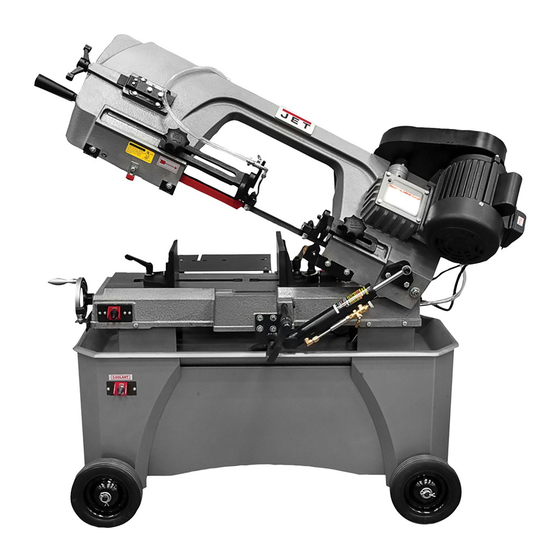
- Page 1 Operating Instructions and Parts Manual Horizontal-Vertical Band Saw Models HVBS-712, HVBS-712D HVBS-712D Deluxe model shown 427 New Sanford Road LaVergne, Tennessee 37086 Part No. M-414559 Ph.: 800-274-6848 Edition 4 03/2016 www.jettools.com Copyright © 2015 JET...
-
Page 2: Important Safety Instructions
3. Do not use this band saw for other than its should be carefully checked to determine that it intended use. If used for other purposes, JET will operate properly and perform its intended function. Check for alignment of moving parts,... -
Page 3: On-Off Switch Padlock
23. Maintain tools with care. Keep saw blades 31. Feed work into a blade or cutter only against the sharp and clean for the best and safest direction of rotation of the blade or cutter. performance. Follow instructions for lubricating 32. -
Page 4: Table Of Contents
11.2 Operational problems ..........................20 12.0 Replacement Parts ............................. 21 12.1.1 HVBS-712/712D Bed and Stand Assembly – Exploded View ............. 22 12.1.2 HVBS-712/712D Bow Assembly – Exploded View ................23 12.1.3 HVBS-712/712D – Parts List ....................... 24 ... -
Page 5: About This Manual
If there are questions or comments, please contact your local supplier or JET. JET can also be reached at our web site: www.jettools.com. -
Page 6: Specifications
5.0 Specifications Model number ..............HVBS-712D ............ HVBS-712 Stock number ................ 414560 ............414559 Motor and electricals: Main motor: Motor type…………..……………………..…totally enclosed fan cooled, induction, capacitor start ....Horsepower ............3/4 HP (0.56 kW) ......... 3/4 HP (0.56 kW) Phase ..................1 ..............1 Voltage .......... - Page 7 Shipping weight ..........418 lbs. (190 kg) .......... 418 lbs. (190 kg) The specifications in this manual were current at time of publication, but because of our policy of continuous improvement, JET reserves the right to change specifications at any time and without prior notice, without incurring obligations.
-
Page 8: Setup And Assembly
6.2 Tools required for assembly 6.0 Setup and assembly Wrenches, 10mm and 19mm #2 cross point screwdriver Read and understand all Pliers instructions before attempting assembly. Band Saw must be disconnected from power during 6.3 Unpacking and cleanup all assembly procedures. Failure to comply may cause serious injury. - Page 9 Figure 6-4: shipping bracket removal 4. Install handle with flat washers and nut (C, Figure 6-7: installing work stop (712 only) Figure 6-5), using 19mm wrench. To install, 6. Slide pulley cover (A, Figure 6-8) over spindles raise bow to vertical position and open guard. secure with screws...
-
Page 10: Coolant Tank Preparation
Note: In Canada, the use of a temporary adaptor is not permitted by the Canadian Electrical The HVBS-712 and HVBS-712D Band Saw is rated Code, C22.1. at 115/230V power, and is pre-wired for 115 volt. -
Page 11: Voltage Conversion
reconnection, the tool should comply with all local Ampere Total length of Volts Rating cord in feet codes and ordinances. More More 7.2 Voltage conversion Than Than Conversion from 115V to 230V must be done by a qualified electrician. The Band Saw is prewired for 115 volt. To change incoming leads for 230 volt operation: Recommended 1. -
Page 12: Blade Speed
8.3 Blade Speed complete, reinstall coolant valve assembly and tighten set screw (C). 1. Disconnect band saw from power source. 5. Verify that blade guide bearings are set 2. Place bow in horizontal position. correctly in relation to blade (see sect. 8.6). 3. -
Page 13: Blade Replacement
Figure 8-8 Figure 8-7: blade guide adjustment 8. Install red blade guard with screws. 8.5 Blade replacement 9. Tension blade fully (see sect. 8.8 Blade tension.) A general-use variable-tooth blade is provided with this band saw. 10. Place two to three drops of lightweight oil on blade. -
Page 14: Chip Brush
8.7 Chip brush set screw and allow blade to respond to changes. The wire chip brush must be properly adjusted and maintained in working condition; otherwise damage Keep fingers clear of blade to blade can occur. Adjust brush so that its bristles and wheel to avoid injury. -
Page 15: Setting Feed Rate
6. Use a micrometer to measure the thickness variation of the disk you have cut from the bar stock. Measure at top and bottom of disk. Figure 8-12: feed rate adjustment 8.12 Counterbalance spring The counterbalance spring helps control amount of weight, or feed pressure, the bow puts on workpiece when hydraulic control valve is fully open. -
Page 16: Blade-To-Table Squareness
8.13 Blade-to-table squareness The blade must be perpendicular to table to ensure a straight cut. This setting should be confirmed by the user. Special blade setting gauges can be purchased for this type of inspection; however, it can also be done using more common shop items, as follows. -
Page 17: Vise Positioning (712 Only)
However, the must be firmly secured in vise. Do not reach into following procedure will be adequate for break-in of cutting area during cutting operations. JET-supplied blades on lower alloy ferrous materials. -
Page 18: Evaluating Cutting Efficiency
Check guide bearings frequently to make sure that they are properly adjusted and turning freely. Periodically inspect belt for wear or fraying. Replace if needed. To prevent corrosion of machined surfaces when a soluble oil is used as coolant, pay particular attention to wiping dry the surfaces where fluid accumulates and does not evaporate quickly, such as between machine bed and vise. -
Page 19: Coolant Level
80% of full capacity. Full capacity is 9 liters (2.5 gal). Follow coolant manufacturer’s instructions for proper use and disposal. 11.0 Troubleshooting HVBS-712/712D Band Saw 11.1 Mechanical and electrical problems Symptom Possible Cause Correction * Motor will not start. -
Page 20: Operational Problems
11.2 Operational problems Symptom Possible Cause Correction Cuts not square. Blade not square to vise/material. Adjust vise square to blade. Blade surface not perpendicular to Adjust blade guides until perpendicular. table. Workpiece shifting in vise. Properly secure workpiece by tightening vise handles. -
Page 21: Replacement Parts
Some parts are shown for reference only, and may not be available individually. Non-proprietary parts, such as fasteners, can usually be found at local hardware stores, or may be ordered from JET. -
Page 22: Hvbs-712/712D Bed And Stand Assembly - Exploded View
12.1.1 HVBS-712/712D Bed and Stand Assembly – Exploded View... -
Page 23: Hvbs-712/712D Bow Assembly - Exploded View
12.1.2 HVBS-712/712D Bow Assembly – Exploded View... -
Page 24: Hvbs-712/712D - Parts List
12.1.3 HVBS-712/712D – Parts List Index No Part No Description Size ....HVBS712-SA .... Stand Assembly (includes #1 thru 5) ............. 1 1 ....HVBS712-01 ..... Water Tray ..................... 1 2 ....HVBS712-02 ..... Stand – Left ....................1 3 .... - Page 25 Index No Part No Description Size 59 ....HVBS7MW-37 ... Support Plate ....................1 60 ....HVBS7MW-38 ... Stop Screw ....................1 61 ....TS-0561021 ....Hex Nut ..............5/16" ......2 62 ....HVBS712-62 ..... Plastic Knob ............M12 ....... 1 63 ....
- Page 26 Index No Part No Description Size 101-2 ..TS-0680041 ....Flat Washer ............3/8” ........ 1 102 .... HVBS712-102W ..Hose ............... 1" ........1 103 .... HVBS712-103W ..Coolant Pump ............1/8HP 115/230V ... 1 104 .... TS-0050031 ....Hex Cap Screw ............1/4" x 3/4"...... 4 107 ....
- Page 27 Index No Part No Description Size 163 .... HVBS712D-163..Adjustable Bracket – Left (712D only) ..... Deluxe Model ....1 163-1 ..HVBS712-163-1 ..Adjustable Bracket – Left (712 only) ......Base model ....1 164 .... HVBS712-164W ..Blade Guard....................1 164-1 ..
- Page 28 228 .... HVBS7MW-46 ... Stop Rod (712 only) ..........Base model ....1 ....JET-113..... JET Logo with 3M Adhesive (not shown) ....113 x 47mm ....1 ....LM000136 ....ID Label HVBS-712 (not shown)......Base model ....1 ....
-
Page 29: Electrical Connections - Hvbs-712/712D Band Saw
13.0 Electrical Connections – HVBS-712/712D Band Saw... -
Page 30: Warranty And Service
Accessories; Shop Tools; Warehouse & Dock products; Hand Tools; Air Tools NOTE: JET is a division of JPW Industries, Inc. References in this document to JET also apply to JPW Industries, Inc., or any of its successors in interest to the JET brand. - Page 31 This page intentionally left blank.
- Page 32 427 New Sanford Road LaVergne, Tennessee 37086 Phone: 800-274-6848 www.jettools.com...
Need help?
Do you have a question about the HVBS-712 and is the answer not in the manual?
Questions and answers