YASKAWA L1000A Technical Manual
200 v class: 1.5 to 110 kw (2 to 150 hp)
400 v class: 1.5 to 315 kw (2 to 500 hp)
600 v class: 1.5 to 160 kw (2 to 250 hp)
Hide thumbs
Also See for L1000A:
- Technical manual (452 pages) ,
- Quick start manual (247 pages) ,
- Installation manual (20 pages)
Table of Contents
Advertisement
YASKAWA AC Drive-L1000A
AC Drive for Elevator Applications
Technical Manual
Type: CIMR-LUA
Models: 200 V Class: 1.5 to 110 kW (2 to 150 HP)
400 V Class: 1.5 to 315 kW (2 to 500 HP)
600 V Class: 1.5 to 160 kW (2 to 250 HP)
To properly use the product, read this manual thoroughly and retain
for easy reference, inspection, and maintenance. Ensure the end user
receives this manual.
MANUAL NO. SIEP C710616 38F
1
1
Receiving
2
2
Mechanical Installation
3
3
Electrical Installation
Start-Up Programming &
4
4
Operation
5
5
Parameter Details
6
6
Troubleshooting
Periodic Inspection &
7
7
Maintenance
Peripheral Devices &
8
8
Options
A
A
Specifications
B
B
Parameter List
MEMOBUS/Modbus
C
C
Communications
D
D
Standards Compliance
E
E
Quick Reference Sheet
Advertisement
Chapters
Table of Contents
Troubleshooting

Related Manuals for YASKAWA L1000A


Summary of Contents for YASKAWA L1000A
- Page 1 YASKAWA AC Drive-L1000A AC Drive for Elevator Applications Technical Manual Type: CIMR-LUA Models: 200 V Class: 1.5 to 110 kW (2 to 150 HP) 400 V Class: 1.5 to 315 kW (2 to 500 HP) 600 V Class: 1.5 to 160 kW (2 to 250 HP) To properly use the product, read this manual thoroughly and retain for easy reference, inspection, and maintenance.
- Page 2 Yaskawa. No patent liability is assumed with respect to the use of the information contained herein. Moreover, because Yaskawa is constantly striving to improve its high-quality products, the...
-
Page 3: Quick Reference
Every precaution has been taken in the preparation of this manual. Nevertheless, Yaskawa assumes no responsibility for errors or omissions. Neither is any liability assumed for damages resulting from the use of the information contained in this publication. - Page 4 YASKAWA ELECTRIC SIEP C710616 38F YASKAWA AC Drive - L1000A Technical Manual...
-
Page 5: Table Of Contents
L1000A Model Overview ........ - Page 6 Flowchart D: PG Encoder Offset Auto-Tuning ......111 YASKAWA ELECTRIC SIEP C710616 38F YASKAWA AC Drive - L1000A Technical Manual...
- Page 7 C3: Slip Compensation ..........175 YASKAWA ELECTRIC SIEP C710616 38F YASKAWA AC Drive - L1000A Technical Manual...
- Page 8 S4: Rescue Operation ..........264 YASKAWA ELECTRIC SIEP C710616 38F YASKAWA AC Drive - L1000A Technical Manual...
- Page 9 Cooling Fan Replacement: CIMR-LU40370 ......338 Cooling Fan Replacement: CIMR-LU40450 and 40605 ....340 YASKAWA ELECTRIC SIEP C710616 38F YASKAWA AC Drive - L1000A Technical Manual...
- Page 10 Operator Related Parameters ........421 YASKAWA ELECTRIC SIEP C710616 38F YASKAWA AC Drive - L1000A Technical Manual...
- Page 11 C.12 Self-Diagnostics ........... . 470 YASKAWA ELECTRIC SIEP C710616 38F YASKAWA AC Drive - L1000A Technical Manual...
- Page 12 User Setting Table ........... 505 Index ..........................509 Revision History......................521 YASKAWA ELECTRIC SIEP C710616 38F YASKAWA AC Drive - L1000A Technical Manual...
-
Page 13: Yaskawa Electric Siep C710616 38F Yaskawa Ac Drive - L1000A Technical Manual
Preface & General Safety This section provides safety messages pertinent to this product that, if not heeded, may result in fatality, personal injury, or equipment damage. Yaskawa is not responsible for the consequences of ignoring these instructions. PREFACE ............14 GENERAL SAFETY. -
Page 14: I.1 Preface
Any warnings provided by Yaskawa must be promptly provided to the end user. Yaskawa offers an express warranty only as to the quality of its products in conforming to standards and specifications published in the Yaskawa manual. -
Page 15: Trademarks
• HIPERFACE is a trademark of SICK STEGMANN GmbH & Co., KG. • CANopen is a trademark of CAN in Automation (CiA). • Other companies and product names mentioned in this manual are trademarks of those companies. YASKAWA ELECTRIC SIEP C710616 38F YASKAWA AC Drive - L1000A Technical Manual... -
Page 16: I.2 General Safety
• The products and specifications described in this manual or the content and presentation of the manual may be changed without notice to improve the product and/ or the manual. • When ordering a new copy of the manual due to damage or loss, contact your Yaskawa representative or the nearest Yaskawa sales office and provide the manual number shown on the front cover. -
Page 17: Safety Messages
Do not attempt to modify or alter the drive in any way not explained in this manual. Yaskawa is not responsible for damage caused by modification of the product made by the user. Failure to comply could result in death or serious injury from operation of damaged equipment. - Page 18 Vac maximum (200 V class) and 480 Vac maximum (400 V class), and 600 Vac maximum (600 V class) when protected by branch circuit protection devices specified in this manual. YASKAWA ELECTRIC SIEP C710616 38F YASKAWA AC Drive - L1000A Technical Manual...
- Page 19 Failure to comply could result in damage to the drive and will void warranty. Yaskawa is not responsible for any modification of the product made by the user. This product must not be modified. Failure to comply could result in damage to the drive or braking circuit.
-
Page 20: General Application Precautions
Yaskawa offers protective designs for drives that must be used in areas subjected to oil mist and excessive vibration. Contact Yaskawa or your Yaskawa agent for details. - Page 21 • If the motor is coasting, make sure the power to the drive is turned on and the drive output has completely stopped before closing the load switch to reconnect the drive to the motor. Wiring Yaskawa recommends using ring terminals on all drive models for UL/cUL compliance. Use only the tools recommended by the terminal manufacturer for crimping. Transporting the Drive NOTICE: Never steam clean the drive.
-
Page 22: Motor Application Precautions
PM motor is rotating. • Contact Yaskawa or your Yaskawa agent if you plan to use any PM motor not endorsed by Yaskawa. • When using a holding brake, release the brake prior to starting the motor. Failure to set the proper timing can result in speed loss. -
Page 23: Drive Label Warnings
Customers who intend to use the product described in this manual for devices or systems relating to transportation, health care, space aviation, atomic power, electric power, or in underwater applications must first contact their Yaskawa representatives or the nearest Yaskawa sales office. - Page 24 General Safety YASKAWA ELECTRIC SIEP C710616 38F YASKAWA AC Drive - L1000A Technical Manual...
-
Page 25: Receiving
COMPONENT NAMES ..........31 YASKAWA ELECTRIC SIEP C710616 38F YASKAWA AC Drive - L1000A Technical Manual... -
Page 26: Section Safety
Ensure that the motor is suitable for drive duty and/or the motor service factor is adequate to accommodate the additional heating with the intended operating conditions. YASKAWA ELECTRIC SIEP C710616 38F YASKAWA AC Drive - L1000A Technical Manual... -
Page 27: General Description
<5> These values assume the carrier frequency is not set higher than 3 kHz. Note: Current derating is required when setting the carrier frequency higher. Refer to Carrier Frequency Derating on page 386 details. YASKAWA ELECTRIC SIEP C710616 38F YASKAWA AC Drive - L1000A Technical Manual... -
Page 28: Control Mode Selection
1.2 General Description ◆ Control Mode Selection Table 1.2 gives an overview of the L1000A motor control method (control modes) and their various features. Table 1.2 Control Modes and their Features Permanent Motor Type Induction Motors Comments Magnet Motors Control Mode CLV/PM –... -
Page 29: Model Number And Nameplate Check
<1> 2-1 Kurosaki-shiroishi, Yahatanishi-Ku, Kitakyushu 806-0004 Japan Enclosure type <1> The address of the head office of Yaskawa Electric Corporation (responsible for product liability) is shown on the nameplate. Figure 1.1 Nameplate Information YASKAWA ELECTRIC SIEP C710616 38F YASKAWA AC Drive - L1000A Technical Manual... -
Page 30: Model Number
– – 40304 – – – – – – 40370 – – – – – – 40450 – – – – – – 40605 400-450-500 – – – YASKAWA ELECTRIC SIEP C710616 38F YASKAWA AC Drive - L1000A Technical Manual... -
Page 31: Component Names
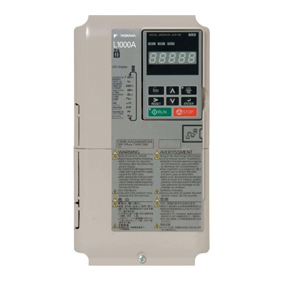
Drive models CIMR-LU20008D, 20011D, 40005D, and 50003D do not have a cooling fan or fan finger guard. Exploded View of IP00 Enclosure Drive with Figure 1.2 Top Protective Cover (CIMR-LU2 0025D) YASKAWA ELECTRIC SIEP C710616 38F YASKAWA AC Drive - L1000A Technical Manual... - Page 32 F – Optional 24 V DC power M – Terminal cover supply connector cover G – Terminal board Figure 1.3 Exploded View of IP00 Enclosure Drive with Top Protective Cover (CIMR-LU20085D) YASKAWA ELECTRIC SIEP C710616 38F YASKAWA AC Drive - L1000A Technical Manual...
- Page 33 F – Fan finger guard M – Drive cover G – Cooling fan N – Terminal cover Figure 1.4 Exploded view of IP00 Enclosure Drive with Top Protective Cover (CIMR-LU40150D) YASKAWA ELECTRIC SIEP C710616 38F YASKAWA AC Drive - L1000A Technical Manual...
-
Page 34: Ip00 Enclosure
E – Fan finger guard L – Drive cover F – Cooling fan M – Terminal cover G – Fan unit case Figure 1.5 Exploded view of IP00/Open Type Enclosure Components (CIMR-LU20215A) YASKAWA ELECTRIC SIEP C710616 38F YASKAWA AC Drive - L1000A Technical Manual... - Page 35 G – Fan unit case N – Front cover screw <1> Drive models 20346, 20415, and 40304 have a built-in circulation fan. Figure 1.6 Exploded view of IP00/Open Type Enclosure Components (CIMR-LU20346A) YASKAWA ELECTRIC SIEP C710616 38F YASKAWA AC Drive - L1000A Technical Manual...
- Page 36 N – Front cover G – Fan unit case O – Circulation fan H – Digital operator P – Terminal cover Figure 1.7 Exploded view of IP00/Open Type Enclosure Components (CIMR-LU40370A) YASKAWA ELECTRIC SIEP C710616 38F YASKAWA AC Drive - L1000A Technical Manual...
- Page 37 H – Fan unit case Q – Circuit board cooling fan unit case I – Circulation Fan Figure 1.8 Exploded view of IP00/Open Type Enclosure Components (CIMR-LU40450A, 40605A) YASKAWA ELECTRIC SIEP C710616 38F YASKAWA AC Drive - L1000A Technical Manual...
-
Page 38: Front Views
I – Option card connector (CN5-B) E – Terminal board (Refer to Control J – Option card connector (CN5-A) Circuit Wiring on page Figure 1.9 Front View of Drives YASKAWA ELECTRIC SIEP C710616 38F YASKAWA AC Drive - L1000A Technical Manual... -
Page 39: Mechanical Installation
MECHANICAL INSTALLATION ........42 YASKAWA ELECTRIC SIEP C710616 38F YASKAWA AC Drive - L1000A Technical Manual... -
Page 40: Section Safety
Do not carry the drive by the front cover or the terminal cover. Failure to comply may result in minor or moderate injury from the main body of the drive falling. YASKAWA ELECTRIC SIEP C710616 38F YASKAWA AC Drive - L1000A Technical Manual... - Page 41 Improper application of peripheral devices could result in malfunction of drive due to electrical interference. Follow manufacturers recommendations when installing electrical devices near the drive and take precautions to shield the drive from electrical interference. YASKAWA ELECTRIC SIEP C710616 38F YASKAWA AC Drive - L1000A Technical Manual...
-
Page 42: Mechanical Installation
Place a temporary cover over the top of the drive during installation. Remove the temporary cover before startup, as the cover will reduce ventilation and cause the drive to overheat. YASKAWA ELECTRIC SIEP C710616 38F YASKAWA AC Drive - L1000A Technical Manual... -
Page 43: Installation Orientation And Spacing
A – 50 mm (1.97 in.) minimum C – 120 mm (4.72 in.) minimum B – 30 mm (1.18 in.) minimum D – Airflow direction Figure 2.2 Correct Installation Spacing YASKAWA ELECTRIC SIEP C710616 38F YASKAWA AC Drive - L1000A Technical Manual... -
Page 44: Instructions On Installation
90 degrees. Figure 2.4 Figure 2.4 Adjusting Angle of Eye Bolts (CIMR-LU20346, 20415, 40216 to 40605, and 50172 to 50200) YASKAWA ELECTRIC SIEP C710616 38F YASKAWA AC Drive - L1000A Technical Manual... -
Page 45: Top Protective Cover
Remove the top protective cover and then remove the screws at the four corners of the cover with a straight-edge screwdriver. Figure 2.7 Top Protective Cover Mounting Holes Top Protective Cover Mounting Holes YEA_TMonly Figure 2.7 Removing the Top Protective Cover YASKAWA ELECTRIC SIEP C710616 38F YASKAWA AC Drive - L1000A Technical Manual... -
Page 46: Digital Operator Remote Usage
Figure 2.9 Drive Operator Comm. Port S / N : J007XE273710001 common_ TMonly Communication Cable Connector Figure 2.9 Communication Cable Connection YASKAWA ELECTRIC SIEP C710616 38F YASKAWA AC Drive - L1000A Technical Manual... - Page 47 Position the digital operator so the display faces outwards, and mount it to the enclosure panel as shown in Figure 2.11. Figure 2.10 M3 × 6 Digital Operator Phillips recessed pan head machine screw × 2 Enclosure panel common_TMonly Figure 2.11 External/Face-Mount Installation YASKAWA ELECTRIC SIEP C710616 38F YASKAWA AC Drive - L1000A Technical Manual...
- Page 48 Unit: mm (in) Figure 2.12 Panel Cut-Out Dimensions (External/Face-Mount Installation) Internal/Flush-Mount An internal flush-mount requires an installation support set that must be purchased separately. Contact a Yaskawa representative to order an installation support set and mounting hardware. Figure 2.13 illustrates how to attach the Installation Support Set A.
-
Page 49: Exterior And Mounting Dimensions
(17.13) (0.30) (3.94) (0.09) (0.09) (55.1) 0145 (12.80) (21.65) (11.14) (10.24) (21.06) (0.30) (4.33) (0.09) (0.09) (81.6) 0180 (12.80) (21.65) (11.14) (10.24) (21.06) (0.30) (4.33) (0.09) (0.09) (83.8) YASKAWA ELECTRIC SIEP C710616 38F YASKAWA AC Drive - L1000A Technical Manual... - Page 50 (4.33) (0.09) (0.09) (90.4) 0077 (12.80) (21.65) (11.14) (10.24) (21.06) (0.30) (4.33) (0.09) (0.09) (90.4) 12.5 80.5 0099 (17.72) (27.76) (12.99) (12.80) (26.77) (0.49) (5.12) (0.13) (0.13) (177.5) YASKAWA ELECTRIC SIEP C710616 38F YASKAWA AC Drive - L1000A Technical Manual...
- Page 51 (0.13) (176.4) 0346 – (19.69) (31.50) (13.78) (14.57) (0.39) (30.43) (0.51) (5.12) (0.18) (0.18) (216.1) 0415 – (19.69) (31.50) (13.78) (14.57) (0.39) (30.43) (0.51) (5.12) (0.18) (0.18) (218.3) YASKAWA ELECTRIC SIEP C710616 38F YASKAWA AC Drive - L1000A Technical Manual...
- Page 52 (0.13) (174.2) 0172 – (19.69) (31.50) (13.78) (14.57) (0.39) (30.43) (0.51) (5.12) (0.18) (0.18) (235.9) 0200 – (19.69) (31.50) (13.78) (14.57) (0.39) (30.43) (0.51) (5.12) (0.18) (0.18) (235.9) YASKAWA ELECTRIC SIEP C710616 38F YASKAWA AC Drive - L1000A Technical Manual...
-
Page 53: Electrical Installation
3.12 WIRING CHECKLIST..........88 YASKAWA ELECTRIC SIEP C710616 38F YASKAWA AC Drive - L1000A Technical Manual... -
Page 54: Section Safety
Alternatively a protective earthing conductor with a cross section of at least 10 mm (Cu) or 16 mm (Al) must be used. YASKAWA ELECTRIC SIEP C710616 38F YASKAWA AC Drive - L1000A Technical Manual... - Page 55 • Do not connect AC line power to output terminals U, V, and W. • Make sure that the power supply lines are connected to main circuit input terminals R/L1, S/L2, T/L3 (or R/L1 and S/ L2 for single-phase power). YASKAWA ELECTRIC SIEP C710616 38F YASKAWA AC Drive - L1000A Technical Manual...
- Page 56 Failure to comply could result in damage to the drive and will void warranty. Yaskawa is not responsible for any modification of the product made by the user. This product must not be modified. Check all the wiring to ensure that all connections are correct after installing the drive and connecting any other devices.
- Page 57 Insulate shields with heat shrink tubing or tape to prevent contact with other signal lines and equipment. Improper wiring practices could result in drive or equipment damage due to short circuit. YASKAWA ELECTRIC SIEP C710616 38F YASKAWA AC Drive - L1000A Technical Manual...
-
Page 58: Standard Connection Diagram
NOTICE: The minimum load for the multi-function relay output MA-MB-MC is 10 mA. If a circuit requires less than 10 mA (reference value), connect it to a photocoupler output (P1-C1, P2-C2). Improper application of peripheral devices could result in damage to the photocoupler output of the drive. YASKAWA ELECTRIC SIEP C710616 38F YASKAWA AC Drive - L1000A Technical Manual... - Page 59 Supplying power to the control circuit separately from the main circuit requires a 24 V power supply (option). <6> For control modes that do not use a motor speed feedback signal, PG option card wiring is not necessary. YASKAWA ELECTRIC SIEP C710616 38F YASKAWA AC Drive - L1000A Technical Manual...
- Page 60 <14> Wire fault contact outputs MA, MB, and MC. Wire so that a fault will open the safety circuit and interrupt drive output. <15> When using the Programming Mode to edit parameter settings, L1000A will not accept an Up/Down command. If the drive still will not run when an Up/Down command has been entered and no fault is present, then use the "Drive ready"...
-
Page 61: Main Circuit Connection Diagram
T/L3 W/T3 YEA_co – – YEA_co mmon mmon 24 V Control Control Gate board Operator Power Gate board Operator board board Supply Figure 3.2 Drive main circuit configurations YASKAWA ELECTRIC SIEP C710616 38F YASKAWA AC Drive - L1000A Technical Manual... -
Page 62: Terminal Block Configuration
V/T2 W/T3 U/T1 Figure 3.3 Main Circuit Terminal Block Configuration <1> Terminal board design differs slightly for models CIMR-LU20215 through 20415, 40180 through 40304, and 50099 through 50200. YASKAWA ELECTRIC SIEP C710616 38F YASKAWA AC Drive - L1000A Technical Manual... -
Page 63: Terminal Cover
Note: The shape of the terminal covers and the numbers of screws differ depending on the drive models. Refer to Component Names on page 31 for details. Figure 3.5 YEA_common Figure 3.6 Removing the Terminal Cover YASKAWA ELECTRIC SIEP C710616 38F YASKAWA AC Drive - L1000A Technical Manual... - Page 64 Figure 3.8 YEA_common Connect ground wiring first, followed by the main circuit, and then wire the control circuit. Figure 3.9 Reattaching the Terminal Cover YASKAWA ELECTRIC SIEP C710616 38F YASKAWA AC Drive - L1000A Technical Manual...
-
Page 65: Digital Operator And
Figure 3.11 YEA_common Figure 3.12 Remove the Front Cover (Models CIMR-LU20008 to 20075, 40005 to 40039, and 50003 to 50027) YASKAWA ELECTRIC SIEP C710616 38F YASKAWA AC Drive - L1000A Technical Manual... - Page 66 Unhook the left side of the front cover then swing the left side towards you as shown in Figure 3.14 until the cover comes off. Figure 3.13 Figure 3.14 Remove the Front Cover (Models CIMR-LU20085 to 20415, 40045 to 40605, and 50032 to 50200) YASKAWA ELECTRIC SIEP C710616 38F YASKAWA AC Drive - L1000A Technical Manual...
- Page 67 (Models CIMR- LU20085 to 20415, 40045 to 40605, and 50032 to 50200) After connecting the hooks to the drive, press firmly on the cover to lock it into place. YASKAWA ELECTRIC SIEP C710616 38F YASKAWA AC Drive - L1000A Technical Manual...
-
Page 68: Main Circuit Wiring
Note: Use terminal B1 and - terminals when installing the braking unit (CDBR type) to the drives with built-in braking transistor (20008 to 20115, 40005 to 40060, and 50003 to 50041). YASKAWA ELECTRIC SIEP C710616 38F YASKAWA AC Drive - L1000A Technical Manual... -
Page 69: Protecting Main Circuit Terminals
Crimp Terminal Size on page 487 for closed-loop crimp terminal recommendations. The wire gauges listed in the following tables are Yaskawa recommendations. Refer to local codes for proper wire gauge selections. YASKAWA ELECTRIC SIEP C710616 38F YASKAWA AC Drive - L1000A Technical Manual... - Page 70 U/T1, V/T2, W/T3 10 to 1/0 9 to 11 –, +1 – 2 to 1/0 20085 (79.7 to 97.4) B1, B2 – 6 to 1/0 6 to 4 YASKAWA ELECTRIC SIEP C710616 38F YASKAWA AC Drive - L1000A Technical Manual...
- Page 71 14 to 10 40005 1.2 to 1.5 –, +1, +2 – 14 to 10 40006 (10.6 to 13.3) 40007 B1, B2 – 14 to 10 14 to 10 <1> YASKAWA ELECTRIC SIEP C710616 38F YASKAWA AC Drive - L1000A Technical Manual...
- Page 72 6 to 250 U/T1, V/T2, W/T3 6 to 250 9 to 11 –, +1 – 3 to 1/0 40091 (79.7 to 97.4) – 4 to 1/0 6 to 4 YASKAWA ELECTRIC SIEP C710616 38F YASKAWA AC Drive - L1000A Technical Manual...
- Page 73 Note: When connecting peripheral devices and options to the terminals –, +1, +3, B1, and B2, refer to the instruction manuals for each device. For more information, contact Yaskawa or your nearest sales representative. YASKAWA ELECTRIC SIEP C710616 38F YASKAWA AC Drive - L1000A Technical Manual...
- Page 74 R/L1, S/L2, T/L3 10 to 4/0 U/T1, V/T2, W/T3 10 to 4/0 18 to 23 –, +1 – 3 to 4/0 50062 (159 to 204) – 6 to 4/0 YASKAWA ELECTRIC SIEP C710616 38F YASKAWA AC Drive - L1000A Technical Manual...
- Page 75 (283 to 354) –, +1 – 2/0 to 500 50200 18 to 23 – 250 to 300 (159 to 204) 32 to 40 1 to 350 (283 to 354) YASKAWA ELECTRIC SIEP C710616 38F YASKAWA AC Drive - L1000A Technical Manual...
-
Page 76: Main Circuit Terminal And Motor Wiring
5 kHz or less 2 kHz or less Note: When setting carrier frequency for drives running multiple motors, calculate cable length as the total wiring distance to all connected motors. YASKAWA ELECTRIC SIEP C710616 38F YASKAWA AC Drive - L1000A Technical Manual... - Page 77 Improper wiring connections could cause the braking resistor to overheat and cause death or serious injury by fire. Failure to comply may result in damage to the braking circuit or drive. YASKAWA ELECTRIC SIEP C710616 38F YASKAWA AC Drive - L1000A Technical Manual...
-
Page 78: Control Circuit Wiring
Off time of at least 1 ms Set the S3 jumper to select sinking or sourcing, and to select the power supply. Safe Disable function common Common for the Safe Disable function YASKAWA ELECTRIC SIEP C710616 38F YASKAWA AC Drive - L1000A Technical Manual... - Page 79 Figure 3.18 YEA_common A – External power, 48 V max. C – Coil B – Suppression diode D – 50 mA or less Figure 3.19 Connecting a Suppression Diode YASKAWA ELECTRIC SIEP C710616 38F YASKAWA AC Drive - L1000A Technical Manual...
-
Page 80: Terminal Configuration
D – Terminal Block (TB 3) B – Terminal Block (TB 5) E – Terminal Block (TB 4) C – Terminal Block (TB 1) Figure 3.20 Control Circuit Terminal Arrangement YASKAWA ELECTRIC SIEP C710616 38F YASKAWA AC Drive - L1000A Technical Manual... -
Page 81: Wiring The Control Circuit Terminal
(20 to 14) (12) Ferrule-Type Wire Terminals ■ Yaskawa recommends using CRIMPFOX 6, a crimping tool manufactured by PHOENIX CONTACT, to prepare wire ends with insulated sleeves before connecting to the drive. Refer to Table 3.10 for dimensions. Figure 3.20 YEA_common Figure 3.21 Ferrule Dimensions... - Page 82 B – Single wire or stranded wire D – Blade depth of 0.4 mm (0.02 in.) or less Blade width of 2.5 mm (0.10 in.) or less Figure 3.22 Terminal Board Wiring Guide YASKAWA ELECTRIC SIEP C710616 38F YASKAWA AC Drive - L1000A Technical Manual...
-
Page 83: Switches And Jumpers On The Terminal Board
Figure 3.23 YEA_c ommon Jumper S3 Terminal H1/H2 Sink/Source Sel. DIP Switch S2 RS-422/485 Termination Resistor Figure 3.24 Locations of Jumpers and Switches on the Terminal Board YASKAWA ELECTRIC SIEP C710616 38F YASKAWA AC Drive - L1000A Technical Manual... -
Page 84: Control I/O Configuration
External 24 Vdc Power Supply Sinking Mode (NPN) 24 Vdc 24 Vdc External 24 Vdc ± 10% Sourcing Mode (PNP) 24 Vdc 24 Vdc External 24 Vdc ± 10% YASKAWA ELECTRIC SIEP C710616 38F YASKAWA AC Drive - L1000A Technical Manual... -
Page 85: Sinking/Sourcing Mode Selection For Safe Disable Inputs
External 24 Vdc Power Supply Jumper S3 Jumper S3 24 Vdc 24 Vdc External 24 Vdc Sinking Mode Jumper S3 Jumper S3 24 Vdc 24 Vdc External 24 Vdc Sourcing Mode YASKAWA ELECTRIC SIEP C710616 38F YASKAWA AC Drive - L1000A Technical Manual... -
Page 86: Connect To A Pc
The drive can connect to a USB port on a PC using a USB 2.0, AB-type cable (sold separately). After connecting the drive to a PC, Yaskawa DriveWizard Plus software can be used to monitor drive performance and manage parameter settings. -
Page 87: Memobus/Modbus Termination
Internal termination resistor OFF (default setting) Figure 3.25 YEA_TMonly DIP Switch S2 (OFF:default) Figure 3.26 DIP Switch S2 Note: Refer to the MEMOBUS/Modbus Communications on page 443 for details on MEMOBUS/Modbus. YASKAWA ELECTRIC SIEP C710616 38F YASKAWA AC Drive - L1000A Technical Manual... -
Page 88: Wiring Checklist
Analog signal line wiring should not exceed 50 m (164 ft.). – Safe Disable input wiring should not exceed 30 m (98 ft.). – Check the logic of the Safe Disable monitor output signals (terminals DM+ and DM-). YASKAWA ELECTRIC SIEP C710616 38F YASKAWA AC Drive - L1000A Technical Manual... -
Page 89: Start-Up Programming & Operation
SETUP TROUBLESHOOTING AND POSSIBLE SOLUTIONS ....152 VERIFYING PARAMETER SETTINGS AND BACKING UP CHANGES ..156 YASKAWA ELECTRIC SIEP C710616 38F YASKAWA AC Drive - L1000A Technical Manual... -
Page 90: Section Safety
• If the motor is coasting, make sure the power to the drive is turned on and the drive output has completely stopped before closing the load switch. YASKAWA ELECTRIC SIEP C710616 38F YASKAWA AC Drive - L1000A Technical Manual... - Page 91 Failure to comply could result in minor or moderate injury. Shut off the power to the drive when replacing the cooling fan. To prevent burns, wait at least 15 minutes and make sure heatsink has cooled down. YASKAWA ELECTRIC SIEP C710616 38F YASKAWA AC Drive - L1000A Technical Manual...
- Page 92 Correctly set parameter o2-04 when replacing the control terminal board. Failure to comply may result in drive damage due to lack of protective functions and poor drive performance. YASKAWA ELECTRIC SIEP C710616 38F YASKAWA AC Drive - L1000A Technical Manual...
-
Page 93: Using The Digital Operator
<2> The LO/RE key can only switch between LOCAL and REMOTE when the drive is stopped. By default settings the LO/RE key function is disabled. To allow using the LO/RE key for switching between LOCAL and REMOTE, set parameter o2-01 to 1. YASKAWA ELECTRIC SIEP C710616 38F YASKAWA AC Drive - L1000A Technical Manual... -
Page 94: Lcd Display
RESET Pressing resets the existing drive fault or error. <1> Displayed when in Drive Mode. <2> Displayed when in Drive Mode and Monitor Mode. YASKAWA ELECTRIC SIEP C710616 38F YASKAWA AC Drive - L1000A Technical Manual... -
Page 95: The Drive And Operation Status Display
When the drive detects an alarm or error. • When an alarm occurs. Flashing • When oPE is detected. • When a fault or error occurs during Auto-Tuning. Normal operation (no fault or alarm). YASKAWA ELECTRIC SIEP C710616 38F YASKAWA AC Drive - L1000A Technical Manual... -
Page 96: Lo/Re Led And Run Led Indications
Figure 4.3 RUN LED Status and Meaning Figure 4.4 Drive output speed during stop STOP STOP Up/Down common_TM Speed setting only RUN LED Flashing Figure 4.4 RUN LED and Drive Operation YASKAWA ELECTRIC SIEP C710616 38F YASKAWA AC Drive - L1000A Technical Manual... -
Page 97: Menu Structure For Digital Operator
<5> The Speed Reference appears after the initial display which shows the product name. <6> The information that appears on the display will vary depending on the drive. YASKAWA ELECTRIC SIEP C710616 38F YASKAWA AC Drive - L1000A Technical Manual... -
Page 98: The Drive And Programming Modes
DATA - MODE - Programming Parameter Setting Allows the user to access and edit all parameter settings. Refer to Parameter Table on page 394. Mode YEA_common HELP DATA YASKAWA ELECTRIC SIEP C710616 38F YASKAWA AC Drive - L1000A Technical Manual... - Page 99 • Setup Group: Access a list of commonly used parameters to simplify setup (refer to Simplified Setup Using the Setup Group on page 102). • Auto-Tuning Mode: Automatically calculate and set motor parameters to optimize drive performance. YASKAWA ELECTRIC SIEP C710616 38F YASKAWA AC Drive - L1000A Technical Manual...
-
Page 100: Changing Parameter Settings Or Values
“1.50 sec” ← → Press to confirm the change. Entry Accepted -PRMSET- The display automatically returns to the screen shown in Step 4. C1-02= 2.50 sec (0.0~600.00) “1.50 sec” YASKAWA ELECTRIC SIEP C710616 38F YASKAWA AC Drive - L1000A Technical Manual... -
Page 101: Verifying Parameter Changes: Verify Menu
C1-02 appears. “1.50sec” Home DATA - VERIFY - PRG Decel Ramp 1 C1-01=002.50sec Press to access the setting value. Left digit flashes. (0.0~600.00) “1.50sec” Home DATA YASKAWA ELECTRIC SIEP C710616 38F YASKAWA AC Drive - L1000A Technical Manual... -
Page 102: Simplified Setup Using The Setup Group
<1> Use the up and down arrow keys to scroll through the Setup Group. Press the ENTER key to view or change parameter settings. <2> To return to the previous menu without saving changes, press the ESC key. Figure 4.7 Setup Group Example YASKAWA ELECTRIC SIEP C710616 38F YASKAWA AC Drive - L1000A Technical Manual... -
Page 103: Switching Between Local And Remote
Press . The LO/RE light will light up. The drive is now in LOCAL. com - RESET ENTER STOP To set the drive for REMOTE operation, press again. YASKAWA ELECTRIC SIEP C710616 38F YASKAWA AC Drive - L1000A Technical Manual... -
Page 104: Start-Up Flowcharts
Flowchart Purpose Page Installation, wiring, and basic steps required to setup the motor and elevator for operation Auto-Tuning for induction motors Auto-Tuning for PM motors Encoder Offset Auto-Tuning YASKAWA ELECTRIC SIEP C710616 38F YASKAWA AC Drive - L1000A Technical Manual... -
Page 105: Flowchart A: Installation, Wiring, Basic Setup For Motor And Elevator
• Adjust speed control loop (C5- ) etc. FINISH Figure 4.8 Installation, Wiring, Basic Setup for Motor and Elevator Note: Set parameter H5-11 to 1 when setting parameters using MEMOBUS/Modbus communications. YASKAWA ELECTRIC SIEP C710616 38F YASKAWA AC Drive - L1000A Technical Manual... -
Page 106: Power On
Permanent magnet motor with ERN1387 or ERN487 encoder Closed Loop Vector Control for PM motors PG-E3 Yaskawa IPM motor with incremental encoder Closed Loop Vector Control for PM motors PG-X3 YASKAWA ELECTRIC SIEP C710616 38F YASKAWA AC Drive - L1000A Technical Manual... -
Page 107: Motor Rotation Direction Setup
If the value in U1-05 is negative, alter the setting of parameter F1-05. Note: Always set the motor rotation direction prior to the encoder rotation direction. Refer to Motor Rotation Direction Setup on page 107. YASKAWA ELECTRIC SIEP C710616 38F YASKAWA AC Drive - L1000A Technical Manual... -
Page 108: Digital Operator Display Unit Selection
Change parameter o1-03 to setting 4 or 5. The unit and setting values of related parameters will be changed automatically. Refer to o1: Digital Operator Display Selection on page 421 for details. YASKAWA ELECTRIC SIEP C710616 38F YASKAWA AC Drive - L1000A Technical Manual... -
Page 109: Flowchart B: Auto-Tuning For Induction Motors
<1> If an LED operator is used, the display shows “ ”. <2> If an LED operator is used, the display shows “ ”. Figure 4.9 Auto-Tuning for Induction Motors YASKAWA ELECTRIC SIEP C710616 38F YASKAWA AC Drive - L1000A Technical Manual... -
Page 110: Flowchart C: Auto-Tuning For Pm Motors
<1> If an LED operator is used, the display shows “ ”. <2> If an LED operator is used, the display shows “ ”. Figure 4.10 Auto-Tuning for PM Motors YASKAWA ELECTRIC SIEP C710616 38F YASKAWA AC Drive - L1000A Technical Manual... -
Page 111: Flowchart D: Pg Encoder Offset Auto-Tuning
<1> If an LED operator is used, the display shows “ ”. <2> If an LED operator is used, the display shows “ ”. Figure 4.11 PG Encoder Offset Auto-Tuning YASKAWA ELECTRIC SIEP C710616 38F YASKAWA AC Drive - L1000A Technical Manual... -
Page 112: Auto-Tuning
A1-02 – 2, 3 2, 3 0, 1, 2, 3 2, 3 Motor Rated Power T1-02 Motor Rated Voltage T1-03 Motor Rated Current T1-04 Motor Rated Frequency T1-05 YASKAWA ELECTRIC SIEP C710616 38F YASKAWA AC Drive - L1000A Technical Manual... - Page 113 Inductance T2-11 q-Axis Inductance T2-12 Induced Voltage Constant Unit T2-13 Selection Voltage Constant T2-14 <2> PG Number of Pulses per T2-16 Revolution Z Pulse Offset T2-17 deg (mech.) YASKAWA ELECTRIC SIEP C710616 38F YASKAWA AC Drive - L1000A Technical Manual...
- Page 114 3. The setting values of parameters F1-66 to F1-81 are reset to factory default values when A1-03 is set to 2220. The setting values of parameters F1-66 to F1-81 are modified at completion of Auto-Tuning of PG-E3 encoder characteristics. YASKAWA ELECTRIC SIEP C710616 38F YASKAWA AC Drive - L1000A Technical Manual...
-
Page 115: Before Auto-Tuning The Drive
Digital input functions are disabled. Functions the same as during normal operation Auto-Tuning of PG-E3 Encoder Characteristics Digital input functions are disabled. Maintains the status at the start of Auto-Tuning YASKAWA ELECTRIC SIEP C710616 38F YASKAWA AC Drive - L1000A Technical Manual... -
Page 116: Auto-Tuning Interruption And Fault Codes
Save the setting by pressing Entry Accepted - A.TUNE - Tuning Mode The display automatically returns to the display shown in Step 3. ∗0∗ T1-01= 0 Standard Tuning DATA YASKAWA ELECTRIC SIEP C710616 38F YASKAWA AC Drive - L1000A Technical Manual... - Page 117 Enter the required information from the motor nameplate. Press to proceed to the Auto-Tuning start display. Note: These instructions continue from Step 6 in “Enter Data from the Motor Nameplate”. YASKAWA ELECTRIC SIEP C710616 38F YASKAWA AC Drive - L1000A Technical Manual...
-
Page 118: Parameter Settings During Induction Motor Auto-Tuning: T1
<1> <1> <1> Values shown are specific to 200 V class drives. Double value for 400 V class drives. Multiply value by 2.875 for 600 V class drives. YASKAWA ELECTRIC SIEP C710616 38F YASKAWA AC Drive - L1000A Technical Manual... - Page 119 ■ Sets the rated slip for the motor. The default setting displayed is the motor rated slip for a Yaskawa motor calculated from the output power set in T1-02. Enter the data listed on the motor test report. Parameter Name...
-
Page 120: Parameter Settings During Pm Motor Auto-Tuning: T2
Enter the number of motor poles. Parameter Name Setting Range Default T2-08 Number of PM Motor Poles 2 to 120 <1> <1> When PG-E3 option connected: Max setting = 48 YASKAWA ELECTRIC SIEP C710616 38F YASKAWA AC Drive - L1000A Technical Manual... - Page 121 T2-14: PM Motor Induced Voltage Constant ■ Enter the motor induced voltage constant. Parameter Name Setting Range Default T2-14 PM Motor Induced Voltage Constant 0.0 to 2000.0 Depending on T2-02 YASKAWA ELECTRIC SIEP C710616 38F YASKAWA AC Drive - L1000A Technical Manual...
- Page 122 Sets the direction of motor rotation for execution of Auto-Tuning of PG-E3 encoder characteristics (T2-01 = 12). Parameter Name Setting Range Default T2-19 Rotation Direction for Auto-Tuning of PG-E3 Encoder Characteristic 0, 1 Setting 0: Forward (Up) Setting 1: Reverse (Down) YASKAWA ELECTRIC SIEP C710616 38F YASKAWA AC Drive - L1000A Technical Manual...
-
Page 123: Setup Procedure For Elevator Applications
• An Up or Down Signal must be set at the source specified in b1-02. • If a multifunction input is programmed for output contactor feedback (H1- = 56), then the output contactor must be closed. YASKAWA ELECTRIC SIEP C710616 38F YASKAWA AC Drive - L1000A Technical Manual... -
Page 124: Speed Selection Using Digital Inputs (B1-01 = 0)
Speed reference 3 (d1-03 or terminal A1, A2 input value if H3-02 or H3-10 is set to 3) Speed reference 4 (d1-04) Speed reference 5 (d1-05) Speed reference 6 (d1-06) Speed reference 7 (d1-07) Speed reference 8 (d1-08) 0 = Off, 1 = On YASKAWA ELECTRIC SIEP C710616 38F YASKAWA AC Drive - L1000A Technical Manual... - Page 125 Higher Speed Priority is Selected and the Leveling Speed Input is Not Assigned (d1-18 = 1 and H1- ≠ 53) The drive decelerates to the leveling speed (d1-26) when the selected speed reference signal is removed. YASKAWA ELECTRIC SIEP C710616 38F YASKAWA AC Drive - L1000A Technical Manual...
-
Page 126: Multi-Function Terminal Setup
Multi-Function Analog Inputs ■ The H3 parameters assign functions to analog input terminals A1 and A2 analog input functions, refer to Multi-Function Analog Input Terminal Settings on page 219. YASKAWA ELECTRIC SIEP C710616 38F YASKAWA AC Drive - L1000A Technical Manual... -
Page 127: Accel/Decel Ramp And Jerk Settings
Safe disable (terminals H1/H2 on) or Baseblock off (H1- = 8/9) = 51 (Output Cont. Contr.) = 50 (Brake Control) Enabled Figure 4.14 With Up/Down command cleared and U1-05 ≥ S1-26 YASKAWA ELECTRIC SIEP C710616 38F YASKAWA AC Drive - L1000A Technical Manual... -
Page 128: Inspection Operation
• If C1-15 > 0.00, the drive decelerates to stop at the rate set to C1-15, then applies the brake, shuts the output off, and opens the motor contactor. YASKAWA ELECTRIC SIEP C710616 38F YASKAWA AC Drive - L1000A Technical Manual... -
Page 129: Brake Sequence
= 50) Enabled Figure 4.17 Brake Sequence without Torque Compensation at Start Figure 4.17 is divided into time zones. Table 4.11 explains the sequence in each time zone. YASKAWA ELECTRIC SIEP C710616 38F YASKAWA AC Drive - L1000A Technical Manual... - Page 130 = 8/9) Output Contactor Control (H2- = 51) Motor Contactor Response (H1- = 56) Brake Control (H2- = 50) Enabled Figure 4.18 Brake Sequence Using Torque Compensation at Start YASKAWA ELECTRIC SIEP C710616 38F YASKAWA AC Drive - L1000A Technical Manual...
- Page 131 Note the drives internal torque reference monitor U1-09. Stop the drive. Set the value noted in step 4 to parameter S3-29. Set the value noted in step 6 to parameter S3-27. YASKAWA ELECTRIC SIEP C710616 38F YASKAWA AC Drive - L1000A Technical Manual...
- Page 132 Load Condition 2) S3-27 (Torque Compensation Value During Load Condition 1 with Load Condition 1) Figure 4.20 Torque Compensation at start for the Elevator in Up and Down Direction YASKAWA ELECTRIC SIEP C710616 38F YASKAWA AC Drive - L1000A Technical Manual...
-
Page 133: Adjustments For Elevator Ride Comfort
• Adjust the Position Lock at start gain 2 (S3-02). Increase S3-02 if rollback occurs, decrease S3-02 it if vibration occurs. • If the elevator is balanced and oscillation at start occurs, attempt gradually increasing the setting in S3-40 in increments of one pulse. YASKAWA ELECTRIC SIEP C710616 38F YASKAWA AC Drive - L1000A Technical Manual... -
Page 134: Rescue Operation
200 V class drives: 48 to 340 Vdc Absolute PG Encoder with PG-F3 or PG-E3 400 V class drives: 48 to 680 Vdc option card 600 V class drives: 48 to 850 Vdc YASKAWA ELECTRIC SIEP C710616 38F YASKAWA AC Drive - L1000A Technical Manual... - Page 135 Select the configuration that matches your application. Follow the corresponding instructions for wiring and drive settings. For configurations not covered in the list above, contact your Yaskawa representative or our sales office directly for consultation.
- Page 136 600 V class drives and connect it to the control power supply input (CN19). Alternatively use a 24 Vdc battery and an optional 24 V Backup Power Supply Unit. • Enable Light Load Direction Search (S4-01 = 1). YASKAWA ELECTRIC SIEP C710616 38F YASKAWA AC Drive - L1000A Technical Manual...
- Page 137 4.24. When connecting the battery for the control power supply to the L1000A, use the 1.1 m cable packaged with the product. The connector cover must first be removed in order to access connection port CN19 for the battery. Refer to Connecting the Drive and Battery on page 145 for details.
- Page 138 <1> Install the inrush current suppression circuit outside the drive if the DC bus battery voltage is lower than 190 Vdc for 200 V class drives and 380 Vdc for 400 V class drives. Failure to comply will cause the soft-charge bypass relay to remain open and result in damage to the drive. YASKAWA ELECTRIC SIEP C710616 38F YASKAWA AC Drive - L1000A Technical Manual...
- Page 139 Motor rated power (kW) × Operation frequency when running battery (Hz) × 2 × 1000 YEA_common Load current of battery (A) = Battery voltage (Vdc) × 0.6 (Motor efficiency) × Motor rated frequency (Hz) YASKAWA ELECTRIC SIEP C710616 38F YASKAWA AC Drive - L1000A Technical Manual...
- Page 140 Figure 4.24 Voltage Lower Than 190 to 340 Vdc for 200 V Class Drives, 380 to 680 Vdc for 400 V Class Drives, and 500 to 850 Vdc for 600 V Class Drives YASKAWA ELECTRIC SIEP C710616 38F YASKAWA AC Drive - L1000A Technical Manual...
- Page 141 The main circuit battery voltage must be higher than 48 Vdc for 200 V, 400 V, and 600 V class drives. Yaskawa offers a 24 V Power Supply Option for the control circuit that is useful in applications unable to connect to a backup battery greater than 250 V.
- Page 142 380 Vdc for 400 V class drives. Failure to comply will cause the soft-charge bypass relay to remain open and result in damage to the drive. Refer to Table 4.14 for the installation of the inrush current suppression circuit for battery. YASKAWA ELECTRIC SIEP C710616 38F YASKAWA AC Drive - L1000A Technical Manual...
- Page 143 Figure 4.27 Voltage Lower Than 190 to 250 Vdc for 200 V Class Drives, 380 to 500 Vdc for 400 V Class Drives, and 500 to 720 Vdc for 600 V Class Drives YASKAWA ELECTRIC SIEP C710616 38F YASKAWA AC Drive - L1000A Technical Manual...
- Page 144 After the car has stopped, open contactor A. Clear the input terminal set for Rescue Operation (H1- = 55). Close contactor B to return to operation with normal power supply. YASKAWA ELECTRIC SIEP C710616 38F YASKAWA AC Drive - L1000A Technical Manual...
- Page 145 NOTICE: Be sure that the connector fastens at the correct angle to the drive port. The incorrect angle could damage the battery, cable, or connector. Figure 4.25 Port CN19 Press in on the connector clip to plug in the cable. Figure 4.30 Connecting the Cable YASKAWA ELECTRIC SIEP C710616 38F YASKAWA AC Drive - L1000A Technical Manual...
- Page 146 NOTICE: Make sure the cable does not get pinched between the drive and the connector cover, as this could damage the cable. Figure 4.27 Figure 4.32 Reattaching the Connector Cover (2) Figure 4.28 Connect to battery. Figure 4.33 Drive and Battery Connection Complete YASKAWA ELECTRIC SIEP C710616 38F YASKAWA AC Drive - L1000A Technical Manual...
- Page 147 Insert a straight-edge screwdriver into the opening as shown in Figure 4.36, then remove the CN19 connector cover by sliding it as shown in Figure 4.36. Figure 4.31 Figure 4.36 Removing the CN19 Connector Cover YASKAWA ELECTRIC SIEP C710616 38F YASKAWA AC Drive - L1000A Technical Manual...
- Page 148 NOTICE: Make sure the cable does not get pinched between the drive and the CN19 connector cover, as this could damage the cable. Figure 4.34 Downward Leftward Figure 4.39 Sliding the CN19 Connector Cover into Place YASKAWA ELECTRIC SIEP C710616 38F YASKAWA AC Drive - L1000A Technical Manual...
- Page 149 Use a Phillips screwdriver to remove the drive covers. Figure 4.37 A – Front cover 1 C – Terminal cover B – Front cover 2 Figure 4.42 Removing the Connector Cover YASKAWA ELECTRIC SIEP C710616 38F YASKAWA AC Drive - L1000A Technical Manual...
- Page 150 The Torque Limit During Rescue Operation is set in parameter S4-05. After Rescue Operation is complete, the drive utilizes to the torque limits set in the L7 parameters. YASKAWA ELECTRIC SIEP C710616 38F YASKAWA AC Drive - L1000A Technical Manual...
- Page 151 Off (open) = 55 On (closed) Light Load Direction Search status Off (open) = 54 Light load direction Figure 4.46 Light Load Direction Detection (Down) YASKAWA ELECTRIC SIEP C710616 38F YASKAWA AC Drive - L1000A Technical Manual...
-
Page 152: Setup Troubleshooting And Possible Solutions
Set b1-01 to the correct source of the speed reference. 0: Digital operator The speed reference source setting is incorrect. 1: Control circuit terminal (default setting) 2: MEMOBUS/Modbus communications 3: Option card YASKAWA ELECTRIC SIEP C710616 38F YASKAWA AC Drive - L1000A Technical Manual... -
Page 153: Motor Is Too Hot
• Ground the drive and motor properly. • Separate the main circuit wiring and the control lines. • Make sure wires and the motor have been properly grounded. YASKAWA ELECTRIC SIEP C710616 38F YASKAWA AC Drive - L1000A Technical Manual... -
Page 154: Ground Fault Circuit Interrupter (Elcb/Gfci) Trips During Run
The acceleration rate changes too quickly when reaching the Decrease the Jerk at the End of Acceleration. Decrease C2-02 if set in m/s selected speed. increase C2-02 if set in s. YASKAWA ELECTRIC SIEP C710616 38F YASKAWA AC Drive - L1000A Technical Manual... - Page 155 Increase the Carrier Frequency in parameter C6-03. If the carrier frequency is The carrier frequency is too low. noise from the motor. set higher than the default setting, a current derating must be considered. YASKAWA ELECTRIC SIEP C710616 38F YASKAWA AC Drive - L1000A Technical Manual...
-
Page 156: Verifying Parameter Settings And Backing Up Changes
A1-04 correctly matches the value set to A1-05: A1-01, A1-02, A1-03 and A2-01 through A2-32. Note: Parameter A1-05 is hidden from view. To display A1-05, access parameter A1-04 and press simultaneously. YASKAWA ELECTRIC SIEP C710616 38F YASKAWA AC Drive - L1000A Technical Manual... -
Page 157: Copy Function
Note: To obtain the driver and software of USB Copy Unit, Copy Unit Manager and DriveWizardPlus, access these sites: China: http://www.yaskawa.com cn Europe: http://www.yaskawa.eu.com Japan: http://www.e-mechatronics.com U.S.A.: http://www.yaskawa.com Other areas: contact a Yaskawa representative. YASKAWA ELECTRIC SIEP C710616 38F YASKAWA AC Drive - L1000A Technical Manual... - Page 158 4.8 Verifying Parameter Settings and Backing Up Changes YASKAWA ELECTRIC SIEP C710616 38F YASKAWA AC Drive - L1000A Technical Manual...
-
Page 159: Parameter Details
5.12 U: MONITOR PARAMETERS ........275 YASKAWA ELECTRIC SIEP C710616 38F YASKAWA AC Drive - L1000A Technical Manual... -
Page 160: A: Initialization
• If parameters are changed via serial communication, it will not be possible to edit or change parameter settings with the digital operator until an Enter command is issued to the drive from the serial communication. YASKAWA ELECTRIC SIEP C710616 38F YASKAWA AC Drive - L1000A Technical Manual... - Page 161 An oPE04 error appears on the digital operator when a terminal block with settings saved to its built-in memory is installed in a drive that has edited parameters. Set A1-02 to 5550 to use the parameter settings saved to the terminal block memory. YASKAWA ELECTRIC SIEP C710616 38F YASKAWA AC Drive - L1000A Technical Manual...
- Page 162 - MODE - Programming Press until the Parameter Setting Mode screen appears. HELP DATA -PRMSET- Initialization A1-00= Press to enter the parameter menu tree. Select Language ← → YASKAWA ELECTRIC SIEP C710616 38F YASKAWA AC Drive - L1000A Technical Manual...
- Page 163 “02” flashes – – Press to make sure that the setting values cannot be selected. - MODE - Programming Press to return to the first display. HELP DATA YASKAWA ELECTRIC SIEP C710616 38F YASKAWA AC Drive - L1000A Technical Manual...
- Page 164 Note: Parameter settings can be edited after entering the correct password. Performing a 2-wire initialization resets the password to “0000”. Reenter the password to parameter A1-05 after drive initialization. YASKAWA ELECTRIC SIEP C710616 38F YASKAWA AC Drive - L1000A Technical Manual...
-
Page 165: A2: User Parameters
A2-17, the second most recently to A2-18, and so on. Access the User Parameters using the Setup Mode of the digital operator. YASKAWA ELECTRIC SIEP C710616 38F YASKAWA AC Drive - L1000A Technical Manual... -
Page 166: B: Application
2. If the speed reference source is set for Option PCB (b1-01 = 3), but an option board is not installed, an oPE05 Operator Programming Error will be displayed on the digital operator and the drive will not run. YASKAWA ELECTRIC SIEP C710616 38F YASKAWA AC Drive - L1000A Technical Manual... - Page 167 After the Up/Down command is cleared and when the value of U1-05 (Speed Feedback) is lower than the value of S1-26 (Emergency Stop Start Level), the drive ramps to a stop. YASKAWA ELECTRIC SIEP C710616 38F YASKAWA AC Drive - L1000A Technical Manual...
- Page 168 (F1-05) to match the direction of the Up and Down commands. 2. If CLV/PM is used, also perform encoder offset Auto-Tuning. YASKAWA ELECTRIC SIEP C710616 38F YASKAWA AC Drive - L1000A Technical Manual...
-
Page 169: B2: Magnetic Flux Compensation
Figure 5.2 Multi-function Contact On (Closed) Input: Timer Function Off (Open) Multi-function Contact common_TMonly On (Closed) Output: Timer Function Off (Open) b4-01 b4-02 b4-01 b4-02 Figure 5.2 Timer Operation YASKAWA ELECTRIC SIEP C710616 38F YASKAWA AC Drive - L1000A Technical Manual... -
Page 170: B6: Dwell Function
Setting Range Default b7-01 Droop Control Gain 0.0 to 100.0% 0.0% Figure 5.4 Speed Speed reference Droop control gain b7-01 common_TMonly Torque 100% Figure 5.4 Droop Control Gain YASKAWA ELECTRIC SIEP C710616 38F YASKAWA AC Drive - L1000A Technical Manual... -
Page 171: B8: Energy Saving
0.05 s ◆ b8: Energy Saving The Energy Saving function can significantly increase the efficiency of an IPM motor. Note: The Energy Saving function should be used only with a Yaskawa IPM motor. b8-01: Energy Saving Control Selection ■ Enables or disables the Energy Saving function. -
Page 172: C: Tuning
Accel/Decel Ramp Selection 1 (Terminals S3 to S8, H1- = “7”) Accel/Decel Ramp Selection 2 (Terminals S3 to S8, H1- = “1A”) Figure 5.5 Timing Diagram of Accel/Decel Ramp Change YASKAWA ELECTRIC SIEP C710616 38F YASKAWA AC Drive - L1000A Technical Manual... - Page 173 A Fast Stop can be selected as the action the drive should take when certain faults occur, such as L8-03 (Overheat Pre-Alarm Operation Selection). Parameter Name Setting Range Default C1-09 Fast Stop Ramp 0.0 to 600.0 s 1.50 s <1> <1> YASKAWA ELECTRIC SIEP C710616 38F YASKAWA AC Drive - L1000A Technical Manual...
-
Page 174: C2: Jerk Settings
0% speed to 100% maximum speed is expressed in seconds. If o1-03 is set to 5 or 6, then setting units will appear in m/s or ft/s YASKAWA ELECTRIC SIEP C710616 38F YASKAWA AC Drive - L1000A Technical Manual... -
Page 175: C3: Slip Compensation
The slip compensation limit is constant throughout the constant torque range (speed reference ≤ E1-06). In the constant power range (speed reference ≥ E1-06), it is increased based on C3-03 and the output speed as shown in Figure 5.8. YASKAWA ELECTRIC SIEP C710616 38F YASKAWA AC Drive - L1000A Technical Manual... - Page 176 Note: Default setting is 0.0 in V/f Control (A1-02 = 0). Default setting is 1.0 in Open Loop Vector Control (A1-02 = 2) and Closed Loop Vector Control (A1-02 = 3). In Closed Loop Vector Control, slip compensation gain acts as an adaptable gain. YASKAWA ELECTRIC SIEP C710616 38F YASKAWA AC Drive - L1000A Technical Manual...
-
Page 177: C4: Torque Compensation
The drive controls the motor excitation current (d-Axis current) and torque producing current (q-Axis current) separately. Torque compensation affects the torque producing current only. C4-01 works as a factor of the torque reference value that builds the torque producing current reference. YASKAWA ELECTRIC SIEP C710616 38F YASKAWA AC Drive - L1000A Technical Manual... - Page 178 C3-01: Slip Compensation Gain on page 175 for details on adjusting this parameter. Parameter Name Setting Range Default C4-07 Motor 2 Torque Compensation Gain 0.00 to 2.50 1.00 YASKAWA ELECTRIC SIEP C710616 38F YASKAWA AC Drive - L1000A Technical Manual...
-
Page 179: C5: Speed Control Loop
Repeat steps 2 to 6 until the desired riding comfort has been reached. Also refer to Riding Comfort Related Problems on page 154. YASKAWA ELECTRIC SIEP C710616 38F YASKAWA AC Drive - L1000A Technical Manual... - Page 180 P = C5-01 TMonly P, I I = C5-02 P = C5-03 I = C5-04 Speed C5-07 Figure 5.11 Settings at Low and High Speed during Acceleration YASKAWA ELECTRIC SIEP C710616 38F YASKAWA AC Drive - L1000A Technical Manual...
- Page 181 0 Hz Set Vibrational Frequency Filter <1> <2> <1> Available in drive software versions PRG: 7200 or later. <2> The frequencies from 1 to 19 Hz cannot be set. YASKAWA ELECTRIC SIEP C710616 38F YASKAWA AC Drive - L1000A Technical Manual...
-
Page 182: C6: Carrier Frequency
Setting 0: 2-phase/3-phase conversion Setting 1: 2-phase modulation Setting 2: 3-phase modulation Note: The drive rated output current is reduced with setting 2. Contact Yaskawa or a Yaskawa representative for details. C6-09: Carrier Frequency during Rotational Auto-Tuning ■ Determines the carrier frequency while performing Rotational Auto-Tuning. Although this parameter rarely needs to be changed, when overcurrent problems occur when Auto-Tuning a low impedance motor, it may be helpful to set C6-03 to a high value before setting C6-09 to 1. -
Page 183: D: Reference Settings
When d1-18 is set to “3”, parameters d1-19 through d1-23 are not displayed. Refer to Multi-Speed Inputs 1, 2 (d1-18 = 0 or 3) on page 124 for details. YASKAWA ELECTRIC SIEP C710616 38F YASKAWA AC Drive - L1000A Technical Manual... - Page 184 <1> Setting ranges and defaults vary by the setting units determined by parameter o1-03. Refer to Defaults and Setting Ranges by Display Unit Selection (o1-03) on page 442 for details. YASKAWA ELECTRIC SIEP C710616 38F YASKAWA AC Drive - L1000A Technical Manual...
- Page 185 Inspection Operation function when d1-18 = 0/3. Refer to Inspection Operation on page 128 for details. Parameter Name Setting Range Default d1-29 Inspection Speed Detection Level 0.0 to 100.0% 0.0% YASKAWA ELECTRIC SIEP C710616 38F YASKAWA AC Drive - L1000A Technical Manual...
-
Page 186: D6: Field Forcing
This parameter does not normally need to be changed. Parameter Name Setting Range Default d6-06 Field Forcing Limit 100 to 400% 400% YASKAWA ELECTRIC SIEP C710616 38F YASKAWA AC Drive - L1000A Technical Manual... -
Page 187: E: Motor Parameters
<4> Default setting is determined by the drive model (o2-04). <5> Parameter ignored when E1-11 and E1-12 are set to 0.0. <6> Auto-Tuning will set E1-13 to the same value as E1-05. YASKAWA ELECTRIC SIEP C710616 38F YASKAWA AC Drive - L1000A Technical Manual... -
Page 188: E2: Motor Parameters
Sets the motor rated slip in Hz to protect the motor and calculate torque limits. This value is automatically set during Auto-Tuning (Rotational Auto-Tuning, Stationary Auto-Tuning 1 and 2). Parameter Name Setting Range Default E2-02 Motor Rated Slip 0.00 to 20.00 Hz Determined by o2-04 YASKAWA ELECTRIC SIEP C710616 38F YASKAWA AC Drive - L1000A Technical Manual... - Page 189 E2-08. This coefficient is used when operating with constant output. Parameter Name Setting Range Default E2-08 Motor Iron-Core Saturation Coefficient 2 E2-07 to 0.75 0.75 YASKAWA ELECTRIC SIEP C710616 38F YASKAWA AC Drive - L1000A Technical Manual...
- Page 190 Enter the no-load current at rated frequency and rated voltage to E2-03. The no-load current is not usually listed on the nameplate. Contact the motor manufacturer if the data cannot be found. The default setting of the no-load current is for performance with a 4-pole Yaskawa motor. Setting the Number of Motor Poles Only required in V/f Control with PG and Closed Loop Vector Control.
-
Page 191: E3: V/F Pattern For Motor 2
2. To make the V/f pattern a straight line at a frequency lower than E3-07, set E3-09 equal to E3-07. In this case the E3-08 setting is disregarded. 3. Parameters E3-04 through E3-10 are reset to their default values when the drive is initialized. YASKAWA ELECTRIC SIEP C710616 38F YASKAWA AC Drive - L1000A Technical Manual... -
Page 192: E4: Motor 2 Parameters
Sets the number of poles for motor 2. If Auto-Tuning completes successfully, the value entered to T1-06 will be automatically saved to E4-04. Parameter Name Setting Range Default E4-04 Motor 2 Motor Poles 2 to 48 YASKAWA ELECTRIC SIEP C710616 38F YASKAWA AC Drive - L1000A Technical Manual... -
Page 193: E5: Pm Motor Settings
Sets the resistance for one motor phase. Do not enter the line-to-line resistance into E5-05 when measuring the resistance manually. Parameter Name Setting Range Default E5-05 Motor Stator Resistance (Single Phase) 0.000 to 65.000 Ω Determined by o2-04 YASKAWA ELECTRIC SIEP C710616 38F YASKAWA AC Drive - L1000A Technical Manual... - Page 194 Note: 1. Set E5-09 to 0.0 when setting E5-24. However, setting both E5-09 and E5-24 to 0.0 will trigger oPE08. oPE08 will also be triggered if neither E5-09 nor E5-24 are set to 0.0. 2. This parameter is not reset when the drive is initialized using parameter A1-03. YASKAWA ELECTRIC SIEP C710616 38F YASKAWA AC Drive - L1000A Technical Manual...
-
Page 195: F: Option Settings
Setting 2: Fast Stop (uses the Fast Stop ramp set to C1-09) Setting 3: Alarm only Note: Due to potential damage to motor and machinery, refrain from using the “Alarm only” setting except under special circumstances. YASKAWA ELECTRIC SIEP C710616 38F YASKAWA AC Drive - L1000A Technical Manual... - Page 196 Detection Selection Note: A common cause for a dv3 fault is the incorrect setting of E5-11. Make sure the correct encoder offset has been entered to E5-11. YASKAWA ELECTRIC SIEP C710616 38F YASKAWA AC Drive - L1000A Technical Manual...
- Page 197 The use of HIPERFACE encoders requires a PG-F3 option with software version 0104 or later. To identify the PG-F3 software version refer to the PG-F3 labeling in the field designated “C/N” (S + four digit number). YASKAWA ELECTRIC SIEP C710616 38F YASKAWA AC Drive - L1000A Technical Manual...
-
Page 198: F3: Digital Input Card Settings
Determines the type of input for digital option card DI-A3 when o1-03 is set to 0 or 1. Parameter Name Setting Range Default F3-01 0 to 7 DI-A3 Option Card Input Selection YASKAWA ELECTRIC SIEP C710616 38F YASKAWA AC Drive - L1000A Technical Manual... -
Page 199: F4: Analog Monitor Card Settings
-999.9 to 999.9% 100.0% F4-04 Terminal V2 Gain -999.9 to 999.9% 50.0% F4-05 Terminal V1 Bias -999.9 to 999.9% 0.0% F4-06 Terminal V2 Bias -999.9 to 999.9% 0.0% YASKAWA ELECTRIC SIEP C710616 38F YASKAWA AC Drive - L1000A Technical Manual... -
Page 200: F5: Digital Output Card Settings
DO-A3 Output Mode Selection 0 to 2 Setting 0: Separate output functions for each of 8 terminals Setting 1: Binary output Setting 2: Output functions assigned by F5-01 through F5-08 YASKAWA ELECTRIC SIEP C710616 38F YASKAWA AC Drive - L1000A Technical Manual... -
Page 201: F6: Communication Option Card
Selects whether torque limit values are assigned to the drive from the network. Parameter Name Setting Range Default F6-06 0, 1 Torque Limit Selection from Communications Option Setting 0: Disabled Setting 1: Enabled YASKAWA ELECTRIC SIEP C710616 38F YASKAWA AC Drive - L1000A Technical Manual... -
Page 202: Canopen Parameters
◆ CANopen Parameters Parameters F6-35 and F6-36 set up the drive to operate on a CANopen network. Refer to the Yaskawa AC Drive Option CANopen Installation Manual and Technical Manual for details on parameter settings. YASKAWA ELECTRIC SIEP C710616 38F YASKAWA AC Drive - L1000A Technical Manual... -
Page 203: H: Terminal Functions
When the speed reference is not assigned to the input terminals (b1-01 ≠ 1), then the Jog frequency will be activated every time an input terminal set for the Jog frequency reference closes. Note that the speed reference priority selection in d1-18 may disable the Jog frequency. YASKAWA ELECTRIC SIEP C710616 38F YASKAWA AC Drive - L1000A Technical Manual... - Page 204 • To trigger the Fast Stop function with a N.O. switch, set H1- = 15. • To trigger the Fast Stop function with a N.C. switch, set H1- = 17. YASKAWA ELECTRIC SIEP C710616 38F YASKAWA AC Drive - L1000A Technical Manual...
- Page 205 This setting configures a digital input terminal as the input for the timer function. Use this setting combination with the timer function output (H2- = 12). Refer to b4: Delay Timers on page 169 for details. YASKAWA ELECTRIC SIEP C710616 38F YASKAWA AC Drive - L1000A Technical Manual...
- Page 206 Closing a terminal set for “Releveling speed” makes the drive run at the speed reference set to d1-23. Conditions change, however, according to the speed selection mode set in d1-18. Refer to Multi-Speed Inputs 1, 2 (d1-18 = 0 or 3) on page 124 for details. YASKAWA ELECTRIC SIEP C710616 38F YASKAWA AC Drive - L1000A Technical Manual...
- Page 207 This input allows the drive to monitor the brake operation and issue a fault if the brake status does not match the brake command (digital output set to H2- = 50). YASKAWA ELECTRIC SIEP C710616 38F YASKAWA AC Drive - L1000A Technical Manual...
-
Page 208: H2: Multi-Function Digital Outputs
S1-01. In all other control modes, the output terminal will close when the output frequency becomes less than or equal to the minimum output frequency set for E1-09. YASKAWA ELECTRIC SIEP C710616 38F YASKAWA AC Drive - L1000A Technical Manual... - Page 209 Speed Agree 1 Figure 5.20 User Set Speed Agree 1 Time Chart Refer to L4-01, L4-02: Speed Agreement Detection Level and Detection Width on page 229 for more instructions. YASKAWA ELECTRIC SIEP C710616 38F YASKAWA AC Drive - L1000A Technical Manual...
- Page 210 (no detection during baseblock). When L4-07 = 0, the terminal opens during baseblock. Refer to L4-01, L4-02: Speed Agreement Detection Level and Detection Width on page 229 for more details. YASKAWA ELECTRIC SIEP C710616 38F YASKAWA AC Drive - L1000A Technical Manual...
- Page 211 Torque detection 2 : Closed Output current/torque exceeds (overtorque detection) or is below (undertorque detection) the torque value set in parameter L6-05 for longer than the time specified in parameter L6-06. YASKAWA ELECTRIC SIEP C710616 38F YASKAWA AC Drive - L1000A Technical Manual...
- Page 212 Output speed or motor speed and speed reference are both outside the range of L4-03 ±L4-04. Closed Output speed or motor speed and the speed reference are both with in the range of L4-03 ±L4-04. YASKAWA ELECTRIC SIEP C710616 38F YASKAWA AC Drive - L1000A Technical Manual...
- Page 213 L4-03 is a signed value, speed detection works in the specified direction only. Status Description Open Output speed or motor speed is below L4-03 minus L4-04 or has not exceeded L4-03 yet. Closed Output speed or motor speed exceeded L4-03. YASKAWA ELECTRIC SIEP C710616 38F YASKAWA AC Drive - L1000A Technical Manual...
- Page 214 (H1- = 16). Refer to Setting 16: Motor 2 selection on page 205 for details on switching motors. Status Description Open Motor 1 is selected. Closed Motor 2 is selected. YASKAWA ELECTRIC SIEP C710616 38F YASKAWA AC Drive - L1000A Technical Manual...
- Page 215 No frequency output from drive when stopped with baseblock, stopped with DC injection braking during initial excitation, or stopped with short circuit braking. Closed Drive is outputting frequency. Figure 5.28 Up/Down command Baseblock command Output frequency During run common_ During frequency TMonly Output Figure 5.28 During Frequency Output Time Chart YASKAWA ELECTRIC SIEP C710616 38F YASKAWA AC Drive - L1000A Technical Manual...
- Page 216 Design the external brake sequence to interlock the brake as long as the Motor Pole Position Search has not finished. In this case, the external brake sequence should be designed to interlock the brake during Motor Pole Position Search. YASKAWA ELECTRIC SIEP C710616 38F YASKAWA AC Drive - L1000A Technical Manual...
-
Page 217: H3: Multi-Function Analog Inputs
Multi-Function Analog Input Terminal Settings on page 219 for instructions on how to adjust the signal level. Parameter Name Setting Range Default H3-02 Terminal A1 Function Selection 0 to 1F YASKAWA ELECTRIC SIEP C710616 38F YASKAWA AC Drive - L1000A Technical Manual... - Page 218 0 or 1 Setting 0: 0 to 10 Vdc The input level is 0 to 10 Vdc. Refer to Setting 0: 0 to 10 Vdc on page 217 for details. YASKAWA ELECTRIC SIEP C710616 38F YASKAWA AC Drive - L1000A Technical Manual...
- Page 219 (used as a second speed reference) Auxiliary speed reference 2 Motor Temperature (PTC thermistor input) <1> (used as a third speed reference) <1> Available in drive software PRG: 7017 or later. YASKAWA ELECTRIC SIEP C710616 38F YASKAWA AC Drive - L1000A Technical Manual...
-
Page 220: H4: Multi-Function Analog Outputs
A setting of 031 or 000 applies no drive monitor to the analog output. With this setting, terminal functions as well as FM and AM output levels can be set by a PLC via a communication option or MEMOBUS/Modbus (through mode). YASKAWA ELECTRIC SIEP C710616 38F YASKAWA AC Drive - L1000A Technical Manual... - Page 221 Bias 0% Monitor Value -5 V Gain 50% Bias 0% -10 V 100% Monitor Value -15 V Figure 5.32 Analog Output Gain and Bias Setting Example 1 and 2 YASKAWA ELECTRIC SIEP C710616 38F YASKAWA AC Drive - L1000A Technical Manual...
-
Page 222: H5: Memobus/Modbus Serial Communication
The H5- parameters are used to set up the drive for MEMOBUS/Modbus Communications. Refer to MEMOBUS/ Modbus Communications on page 443 for detailed descriptions of the H5- parameters. YASKAWA ELECTRIC SIEP C710616 38F YASKAWA AC Drive - L1000A Technical Manual... -
Page 223: L: Protection Functions
(check the motor nameplate or overload protection (oL1). A fault is output and the specifications). motor will coast to stop. Continuous 05 33 100 120 167 200 Speed (%) YASKAWA ELECTRIC SIEP C710616 38F YASKAWA AC Drive - L1000A Technical Manual... - Page 224 Motor is designed to effectively cool itself at Continuous operation with 100% load from 0.2% to ultra-low speeds (about 0.2% of base speed). 100% of base speed. 0 0.2 Percent of base speed (%) YASKAWA ELECTRIC SIEP C710616 38F YASKAWA AC Drive - L1000A Technical Manual...
- Page 225 L1-04. Connect the PTC thermistor between terminals AC and A2 as shown in Figure 5.35. Set parameter H3-09 to 0 and parameter H3-10 to E. YASKAWA ELECTRIC SIEP C710616 38F YASKAWA AC Drive - L1000A Technical Manual...
- Page 226 The drive stops the motor using the deceleration time set in parameter C1-09. Setting 3: Alarm only The operation is continued and an oH3 alarm is displayed on the digital operator. YASKAWA ELECTRIC SIEP C710616 38F YASKAWA AC Drive - L1000A Technical Manual...
-
Page 227: L2: Undervoltage Detection
(oL2), or motor overload (oL1). The drive can prevent the motor from stalling and still reach the desired speed without the user needing to change the acceleration or deceleration ramp settings. The Stall Prevention function can be set separately for acceleration, operating at constant speeds, and deceleration. YASKAWA ELECTRIC SIEP C710616 38F YASKAWA AC Drive - L1000A Technical Manual... - Page 228 • Lower L3-02 if stalling occurs when using a motor that is relatively small compared to the drive. • Also set parameter L3-03 when operating the motor in the constant power range. YASKAWA ELECTRIC SIEP C710616 38F YASKAWA AC Drive - L1000A Technical Manual...
-
Page 229: L4: Speed Detection
0.0 to 40.0% 4.0% For details on setting 13, 14, 15, and 16, refer to H2-01 to H2-05: Terminals M1-M2, M3-M4, M5-M6, P1-C1, and P2-C2 Function Selection on page 208. YASKAWA ELECTRIC SIEP C710616 38F YASKAWA AC Drive - L1000A Technical Manual... - Page 230 Sets the speed level for the car door to open. Once the car slows to the speed set in L4-13, a multi-function output terminal set for “Door zone reached” will close (H2- = 52). Parameter Name Setting Range Default L4-13 Door Zone Level 0.0 to 100.0% 0.0% YASKAWA ELECTRIC SIEP C710616 38F YASKAWA AC Drive - L1000A Technical Manual...
-
Page 231: L5: Automatic Fault Reset
When the counter reaches the number set in L5-01, the operation stops and the fault has to be reset manually after correcting the cause. YASKAWA ELECTRIC SIEP C710616 38F YASKAWA AC Drive - L1000A Technical Manual... -
Page 232: L6: Torque Detection
Figure 5.40 Motor current / torque common_TMonly 10% hysteresis 10% hysteresis L6-02/05 L6-03/06 L6-03/06 Torque detection 1 (NO) Torque detection 2 (NO) Figure 5.40 Overtorque Detection Operation YASKAWA ELECTRIC SIEP C710616 38F YASKAWA AC Drive - L1000A Technical Manual... - Page 233 Setting 8: UL3, UL4 at run (Fault) Undertorque detection works as long as a Up/Down command is active. Operation stops and an oL3 or oL4 fault is triggered. YASKAWA ELECTRIC SIEP C710616 38F YASKAWA AC Drive - L1000A Technical Manual...
-
Page 234: L7: Torque Limit
Forward Torque Limit L7-02 0 to 300% 200% Reverse Torque Limit L7-03 0 to 300% 200% Forward Regenerative Torque Limit L7-04 0 to 300% 200% Reverse Regenerative Torque Limit YASKAWA ELECTRIC SIEP C710616 38F YASKAWA AC Drive - L1000A Technical Manual... -
Page 235: L8: Drive Protection
“fault” (H2- = E), this output will be triggered. Setting 3: Alarm only If an overheat alarm occurs, an alarm is output and the drive continues operation. YASKAWA ELECTRIC SIEP C710616 38F YASKAWA AC Drive - L1000A Technical Manual... - Page 236 <1> The setting range changes depending on drive software versions. PRG: 7017 or earlier: 0 to 2 PRG: 7200 or later: 0 to 3 <2> Setting 3 is available in the control mode V/f or OLV. YASKAWA ELECTRIC SIEP C710616 38F YASKAWA AC Drive - L1000A Technical Manual...
- Page 237 By setting the ambient temperature to parameter L8-12 and adjusting the installation method setting in L8-35, the drive rating automatically adapts to safe values. Parameter Name Setting Range Default L8-12 Ambient Temperature Setting -10 to 50°C 40°C YASKAWA ELECTRIC SIEP C710616 38F YASKAWA AC Drive - L1000A Technical Manual...
- Page 238 For an IP00 enclosure drive installed with at a minimum of 30 mm (1.18 in.) space to the next drive or a cabinet wall. Setting 2: IP00 enclosure with top protective cover For an IP00 enclosure drive with top protective cover. The digital operator shows “IP20/NEMA 1, UL Type 1”. YASKAWA ELECTRIC SIEP C710616 38F YASKAWA AC Drive - L1000A Technical Manual...
- Page 239 Enable L8-55 when connecting a braking resistor or a braking resistor unit to the drive built-in braking transistor. Overload Tolerance for Internal Braking Transistor Below, Figure 5.43 show the overload tolerance level for the drive’s built-in braking transistor. YASKAWA ELECTRIC SIEP C710616 38F YASKAWA AC Drive - L1000A Technical Manual...
- Page 240 Safe Disable Operation Drive Ready L8-88 Alarm Display during Safety Disable Alarm Output (H2- = 10) Selection (H2- = 6) 0 (mode 0) ALM flashes 1 (mode1) ALM flashes YASKAWA ELECTRIC SIEP C710616 38F YASKAWA AC Drive - L1000A Technical Manual...
- Page 241 Motor Contactor Feedback command turns off if the current monitoring selection is enabled (L8-89 = 1). This parameter is also used to activate the Motor Current Monitor (H2- = 5C). Parameter Name Setting Range Default L8-99 Current Monitoring Level 0.0 to 50.0% 10.0% YASKAWA ELECTRIC SIEP C710616 38F YASKAWA AC Drive - L1000A Technical Manual...
-
Page 242: N: Special Adjustments
• Increase n2-03 if overvoltage occurs with high inertia loads at the end of acceleration or with sudden load changes. • If setting n2-02 to a higher value, also increase C4-02 (Torque Compensation Delay Time Constant 1) proportionally. YASKAWA ELECTRIC SIEP C710616 38F YASKAWA AC Drive - L1000A Technical Manual... -
Page 243: N5: Inertia Compensation
Sets the time required to accelerate the motor from a full stop up to the rated speed at the rated torque. Parameter Name Setting Range Default n5-02 Motor Acceleration Time 0.001 to 10.000 s Determined by o2-04 YASKAWA ELECTRIC SIEP C710616 38F YASKAWA AC Drive - L1000A Technical Manual... - Page 244 4. Reduce the products of C5-17 × C5-18 if oscillation is a problem. 5. C5-18 to at least 1.1 when using the Speed Feedback Compensation. A setting of 1.0 or less disables the Speed Feedback Compensation. YASKAWA ELECTRIC SIEP C710616 38F YASKAWA AC Drive - L1000A Technical Manual...
- Page 245 Although this parameter rarely requires adjustment, increasing the gain can help improve responsiveness relative to the load. Lower setting if oscillation occurs. Parameter Name Setting Range Default n5-08 Speed Feedback Compensation Gain (P) 0.00 to 300.00 3.00 YASKAWA ELECTRIC SIEP C710616 38F YASKAWA AC Drive - L1000A Technical Manual...
-
Page 246: N6: Online Tuning
Sets the current used for the initial rotor position estimation as a percentage of the motor rated current. Parameter Name Setting Range Default n8-01 Initial Polarity Estimation Current 0 to 100% YASKAWA ELECTRIC SIEP C710616 38F YASKAWA AC Drive - L1000A Technical Manual... - Page 247 Magnet Pole Search Error Detection Selection ■ Enables fault detection for Initial Polarity Estimation (dv8). Parameter Name Setting Range Default n8-86 Magnet Pole Search Error Detection Selection 0 or 1 YASKAWA ELECTRIC SIEP C710616 38F YASKAWA AC Drive - L1000A Technical Manual...
-
Page 248: N9: Current Detection Adjustments
PM motor. Prior to adjusting this value, make sure all other parameters (motor data, speed loop settings) are adjusted correctly. Parameter Name Setting Range Default n9-60 A/D Conversion Start Delay 0.0 to 40.0 μs Determined by o2-04 YASKAWA ELECTRIC SIEP C710616 38F YASKAWA AC Drive - L1000A Technical Manual... -
Page 249: O: Operator Related Settings
Setting 5: Elevator units 2 (speed in m/s, accel/decel rate in m/s , jerk in m/s Setting 6: Elevator units 3 (speed in ft/min, accel/decel rate in ft/s , jerk in ft/s YASKAWA ELECTRIC SIEP C710616 38F YASKAWA AC Drive - L1000A Technical Manual... - Page 250 Some monitors are only available in certain control modes. Parameter Name Setting Range Default 101 to 699 o1-08 Third Line Monitor Selection U1-01 (Speed Reference) to U6-99 (Option Monitor 20) YASKAWA ELECTRIC SIEP C710616 38F YASKAWA AC Drive - L1000A Technical Manual...
- Page 251 Sets the roping ratio. Parameter Name Setting Range Default o1-21 Roping Ratio 1 to 4 Setting 1: 1: 1 Setting 2: 1: 2 Setting 3: 1: 3 Setting 4: 1: 4 YASKAWA ELECTRIC SIEP C710616 38F YASKAWA AC Drive - L1000A Technical Manual...
-
Page 252: O2: Digital Operator Keypad Functions
The STOP key will terminate drive operation even if the Up/Down command source is not assigned to the digital operator. Cycle the Up/Down command to restart the drive if the drive has been stopped by pressing the STOP key. YASKAWA ELECTRIC SIEP C710616 38F YASKAWA AC Drive - L1000A Technical Manual... - Page 253 The ENTER key does not need to be pressed. The speed reference is saved for 5 s after it is changed. The operator display flashes when settings can be made for the frequency reference. Figure 5.47 common_TMonly Figure 5.47 Ready for Setting Speed Reference YASKAWA ELECTRIC SIEP C710616 38F YASKAWA AC Drive - L1000A Technical Manual...
-
Page 254: O3: Copy Function
■ Allows and restricts the use of the Copy function. Parameter Name Setting Range Default o3-02 Copy Allowed Selection 0 or 1 Setting 0: Disabled Setting 1: Enabled YASKAWA ELECTRIC SIEP C710616 38F YASKAWA AC Drive - L1000A Technical Manual... -
Page 255: O4: Maintenance Monitor Settings
Note: The actual maintenance time will depend on the environment where the drive is used. Parameter Name Setting Range Default o4-07 DC Bus Pre-charge Relay Maintenance Setting 0 to 150% YASKAWA ELECTRIC SIEP C710616 38F YASKAWA AC Drive - L1000A Technical Manual... - Page 256 Resets the number of travels counter. The monitor U4-24/25 will show 0. Once o4-13 is set to 1 and the ENTER key is pressed, the counter value is erased and the display returns to 0. YASKAWA ELECTRIC SIEP C710616 38F YASKAWA AC Drive - L1000A Technical Manual...
- Page 257 0: LT1 (cooling fan) bit 1: LT2 (DC bus capacitors) bit 2: LT3 (soft-charge bypass relay) bit 3: LT4 (IGBTs have passed 90% of the their life expectancy) YASKAWA ELECTRIC SIEP C710616 38F YASKAWA AC Drive - L1000A Technical Manual...
-
Page 258: S: Elevator Parameters
A setting of 0.00 disables S1-04. Parameter Name Setting Range Default S1-04 DC Injection / Position Lock Time at Start 0.00 to 10.00 s 0.40 s YASKAWA ELECTRIC SIEP C710616 38F YASKAWA AC Drive - L1000A Technical Manual... - Page 259 0 to 2 <1> <2> <1> Setting 2 is available in drive software versions PRG: 7017 or later. <2> The setting is 0 or 1 for software version PRG: 7016. YASKAWA ELECTRIC SIEP C710616 38F YASKAWA AC Drive - L1000A Technical Manual...
-
Page 260: S2: Slip Compensation For Elevators
Sets the filter time constant applied to the torque signal used for the slip compensation value calculation. Parameter Name Setting Range Default S2-06 Slip Compensation Torque Detection Filter Time Constant 0 to 2000 ms 500 ms YASKAWA ELECTRIC SIEP C710616 38F YASKAWA AC Drive - L1000A Technical Manual... -
Page 261: S3: Start/Stop Optimization
Adjusting the Torque Compensation at Start on page 131 for details. Parameter Name Setting Range Default S3-12 Starting Torque Compensation Bias in Down Direction –40.0 to 40.0% 0.00% YASKAWA ELECTRIC SIEP C710616 38F YASKAWA AC Drive - L1000A Technical Manual... - Page 262 DC Injection at stop is determined as S1-03 × S3-25. Parameter Name Setting Range Default S3-25 DC Injection Gain in Regenerative Operation 0 to 400% 100% YASKAWA ELECTRIC SIEP C710616 38F YASKAWA AC Drive - L1000A Technical Manual...
- Page 263 Sets a maximum value for the torque bias used for Anti-Rollback when Position Lock at start is performed. This setting rarely needs to be changed. Parameter Name Setting Range Default S3-35 Anti-Rollback Torque Bias 2 0.0 to 100.0% 0.0% YASKAWA ELECTRIC SIEP C710616 38F YASKAWA AC Drive - L1000A Technical Manual...
-
Page 264: S4: Rescue Operation
Enables and disables the Light Load Direction Search. Parameter Name Setting Range Default S4-01 Light Load Direction Search Selection 0 to 2 Setting 0: Disabled Setting 1: Enabled Setting 2: Enabled for motor 1 only YASKAWA ELECTRIC SIEP C710616 38F YASKAWA AC Drive - L1000A Technical Manual... - Page 265 Default S4-08 UPS Operation Speed Limit Selection 0 to 2 Setting 0: Disabled Setting 1: Enabled until Light Load Direction Search is complete Setting 2: Enabled until stop YASKAWA ELECTRIC SIEP C710616 38F YASKAWA AC Drive - L1000A Technical Manual...
- Page 266 Setting 0: The setting of parameter d1-25 is used as speed reference for Rescue Operation Setting 1: The speed selected by digital inputs is used as speed reference YASKAWA ELECTRIC SIEP C710616 38F YASKAWA AC Drive - L1000A Technical Manual...
-
Page 267: S5: Short Floor Operation
Advanced Short Floor Input Timing Operating d1-19 speed (Nominal Speed) Constant speed operation at rated speed d1-26 (normal stop (Leveling Speed) sequence) Time = 53 ON(close) (Leveling Speed) <1> YASKAWA ELECTRIC SIEP C710616 38F YASKAWA AC Drive - L1000A Technical Manual... - Page 268 <1> The drive will recognize the speed reference that is lower than the Leveling Speed Detection Level (d1-28) as the leveling speed if the speed priority is set for multi-step speed reference (d1-18 0 or 3). YASKAWA ELECTRIC SIEP C710616 38F YASKAWA AC Drive - L1000A Technical Manual...
- Page 269 50.0 to 200.0% 150.0% Note: Setting S5-05 too low may trigger an overrun due to faster optimum speeds and shortened leveling times. Avoid setting this gain less than 100%. YASKAWA ELECTRIC SIEP C710616 38F YASKAWA AC Drive - L1000A Technical Manual...
- Page 270 The Up/Down command is not active, the speed reference is 0, or the leveling speed reference has been selected by one of the multi-function input terminals (H1-). Leveling speed reference has priority (d1-18 = 2) YASKAWA ELECTRIC SIEP C710616 38F YASKAWA AC Drive - L1000A Technical Manual...
- Page 271 (H1- = 50). H1- = 50 to 53 are open. Multi-step speed sequence (d1-18 = 2) Rated speed reference is not selected Up/Down command is not active. (H1- ≠ 50). YASKAWA ELECTRIC SIEP C710616 38F YASKAWA AC Drive - L1000A Technical Manual...
- Page 272 Sets the speed level for the start of Direct Landing. Direct Landing is disabled if the starting speed for Direct Landing is less than the maximum output speed multiplied by this parameter (E1-04 × S5-13). Parameter Name Setting Range Default S5-13 Direct Landing Minimum Speed Level 0 to 100% YASKAWA ELECTRIC SIEP C710616 38F YASKAWA AC Drive - L1000A Technical Manual...
-
Page 273: S6: Faults For Elevator Applications
(H2- = 50) and an input terminal set for “Brake feedback” (H1- = 79) do not match for the time set to S6-05. Parameter Name Setting Range Default S6-05 Brake Response Error (SE4) Detection Time 0 to 10000 ms 500 ms YASKAWA ELECTRIC SIEP C710616 38F YASKAWA AC Drive - L1000A Technical Manual... -
Page 274: T: Motor Tuning
Safe Disable function, parameter L8-88 must be set to 1. ◆ T: Motor Tuning Auto-Tuning automatically sets and tunes parameters required for optimal motor performance. Refer to Auto-Tuning on page 112 for details on Auto-Tuning parameters. YASKAWA ELECTRIC SIEP C710616 38F YASKAWA AC Drive - L1000A Technical Manual... -
Page 275: U: Monitor Parameters
• Speed Loop and Inertia Compensation control monitors Refer to Figure 5.10 on page for details and an illustration showing where monitors are located in the speed control loop block. YASKAWA ELECTRIC SIEP C710616 38F YASKAWA AC Drive - L1000A Technical Manual... - Page 276 5.12 U: Monitor Parameters YASKAWA ELECTRIC SIEP C710616 38F YASKAWA AC Drive - L1000A Technical Manual...
-
Page 277: Troubleshooting
DIAGNOSING AND RESETTING FAULTS......314 YASKAWA ELECTRIC SIEP C710616 38F YASKAWA AC Drive - L1000A Technical Manual... -
Page 278: Section Safety
Loose electrical connections could result in death or serious injury by fire due to overheating of electrical connections. Improperly tightened terminal screws can also cause erroneous equipment operation. YASKAWA ELECTRIC SIEP C710616 38F YASKAWA AC Drive - L1000A Technical Manual... - Page 279 Failure to comply could result in damage to the drive and will void warranty. Yaskawa is not responsible for modification of the product made by the user. Check all the wiring after installing the drive and connecting other devices to ensure that all connections are correct.
-
Page 280: Drive Alarms, Faults, And Errors
Check the digital operator for information about possible faults if the drive or motor fails to operate. Refer to Using the Digital Operator on page If problems occur that are not covered in this manual, contact the nearest Yaskawa representative with the following information: • Drive model •... -
Page 281: Alarm And Error Displays
Option Card Connection Error (CN5-B) Encoder Z Pulse Fault Z Pulse Noise Fault Detection oFC00 Option Card Connection Error (CN5-C) Inversion Detection oFC01 Option Card Fault (CN5-C) YASKAWA ELECTRIC SIEP C710616 38F YASKAWA AC Drive - L1000A Technical Manual... - Page 282 When one of the faults occurs after successfully starting the drive, the display will show <2> Displayed only for models in compliance with IEC/EN 61508 SIL3 Safety Integrity Level 3. YASKAWA ELECTRIC SIEP C710616 38F YASKAWA AC Drive - L1000A Technical Manual...
- Page 283 MEMOBUS/Modbus Comm. Test Mode Complete No output Encoder Disconnected (for Control Mode with Encoder) PGoH Encoder Disconnected (when using an encoder) MEMOBUS/Modbus Self Test Failed TrPC IGBT Maintenance Time (90%) YASKAWA ELECTRIC SIEP C710616 38F YASKAWA AC Drive - L1000A Technical Manual...
- Page 284 Z Pulse Correction Error Er-02 Alarm Er-22 Initial Rotor Pole Search Error Non-rotating Encoder Offset Tuning Er-03 STOP Button Input Er-23 Warning Er-04 Line-to-Line Resistance Error – – – – YASKAWA ELECTRIC SIEP C710616 38F YASKAWA AC Drive - L1000A Technical Manual...
- Page 285 Model, voltage class, capacity mismatch rdEr Error reading data rEAd Reading parameter settings (flashing) vAEr Voltage class, capacity mismatch vFyE Parameter setting mismatch vrFy Comparing parameter settings (flashing) YASKAWA ELECTRIC SIEP C710616 38F YASKAWA AC Drive - L1000A Technical Manual...
-
Page 286: Fault Detection
There is a self diagnostic error in control circuit. • Set the frequency to the minimum value and interrupt the Run command when the drive finishes decelerating. Connector on the operator is damaged. Replace the operator. YASKAWA ELECTRIC SIEP C710616 38F YASKAWA AC Drive - L1000A Technical Manual... - Page 287 Possible Solution • Cycle power to the drive. Control circuit is damaged. • If the problem continues, replace the control board or the entire drive. Contact Yaskawa or a Yaskawa representative for instructions on replacing the control board. Digital Operator Display...
- Page 288 CPF26 to CPF34 CPU error Cause Possible Solution If the problem continues, replace the control board or the entire drive. Contact Yaskawa or a Yaskawa representative for Hardware is damaged. instructions on replacing the control board. Digital Operator Display Fault Name...
- Page 289 • Reconnect the signal line. • Check for unused terminals set for H1- = 20 to 2B (External Fault). Incorrect multi-function contact input setting • Change the terminal settings. YASKAWA ELECTRIC SIEP C710616 38F YASKAWA AC Drive - L1000A Technical Manual...
- Page 290 Refer to Diagnosing and Resetting Faults on page 314. • If the problem continues, replace the control board or the entire drive. Contact Yaskawa or a Yaskawa representative for instructions on replacing the control board. If the problem continues, replace the control board or the entire drive. Contact Yaskawa or a Yaskawa representative for Hardware problem.
- Page 291 • Cycle power to the drive. Option card or hardware is damaged. • If the problem continues, replace the control board or the entire drive. Contact Yaskawa or a Yaskawa representative for instructions on replacing the control board. YASKAWA ELECTRIC SIEP C710616 38F YASKAWA AC Drive - L1000A Technical Manual...
- Page 292 • Cycle power to the drive. Option card or hardware is damaged. • If the problem continues, replace the control board or the entire drive. Contact Yaskawa or a Yaskawa representative for instructions on replacing the control board. Digital Operator Display...
- Page 293 • Enter the motor rated current as indicated on the motor nameplate (E2-01). • Ensure the motor cooling system is operating normally. • Repair or replace the motor cooling system. YASKAWA ELECTRIC SIEP C710616 38F YASKAWA AC Drive - L1000A Technical Manual...
- Page 294 The current has exceeded the value set for Overtorque Detection 2 (L6-05) for longer than the allowable time (L6-06). Cause Possible Solution Parameter settings are not appropriate for the load. Check the settings of parameters L6-05 and L6-06. YASKAWA ELECTRIC SIEP C710616 38F YASKAWA AC Drive - L1000A Technical Manual...
- Page 295 • Stabilize drive input power or disable phase loss detection. • Check the maintenance time for the capacitors (U4-05). • Replace the capacitor if U4-05 is greater than 90%. For instructions on replacing the capacitor, contact Yaskawa or a Yaskawa representative.
- Page 296 • Cycle power to the drive and check if the fault reoccurs. Refer to Diagnosing and Resetting Faults on page 314. • Replace either the control board or the entire drive. For instructions on replacing the control board, contact Yaskawa or a The control circuit is damaged. Yaskawa representative.
- Page 297 Internal circuitry is damaged. • If the problem continues, replace either the control board or the entire drive. For instructions on replacing the control board, contact Yaskawa or a Yaskawa representative. YASKAWA ELECTRIC SIEP C710616 38F YASKAWA AC Drive - L1000A Technical Manual...
- Page 298 Problem detected with the voltage on the output side of the drive. Cause Possible Solution Replace either the control board or the entire drive. For instructions on replacing the control board, contact Yaskawa or a Yaskawa Hardware is damaged. representative.
-
Page 299: Alarm Detection
A termination resistor must be installed at both ends of a communication line. Slave drives must have the internal termination resistor Termination resistor setting is incorrect. switch set correctly. Place DIP switch S2 to the ON position. YASKAWA ELECTRIC SIEP C710616 38F YASKAWA AC Drive - L1000A Technical Manual... - Page 300 • Check if the unused terminals have been set for H1- = 2C to 2F (External Fault). Multi-function contact inputs are set incorrectly. • Change the terminal settings. YASKAWA ELECTRIC SIEP C710616 38F YASKAWA AC Drive - L1000A Technical Manual...
- Page 301 • If the Safe Disable function is not utilized, check if the terminals H1-HC, and H2-HC are linked. Replace either the control board or the entire drive. For instructions on replacing the control board, contact Yaskawa or your nearest Internally, both Safe Disable channels are broken.
- Page 302 The motor speed feedback exceeded the F1-08 setting. Cause Possible Solutions Inappropriate parameter settings. Check the setting for the overspeed detection level and the overspeed detection time (F1-08 and F1-09). YASKAWA ELECTRIC SIEP C710616 38F YASKAWA AC Drive - L1000A Technical Manual...
- Page 303 Drive output current (or torque in OLV, CLV, CLV/PM) less than L6-05 for longer than L6-06 time. Cause Possible Solutions Inappropriate parameter settings. Check parameters L6-05 and L6-06. The load has dropped or decreased significantly. Check for broken parts in the transmission system. YASKAWA ELECTRIC SIEP C710616 38F YASKAWA AC Drive - L1000A Technical Manual...
- Page 304 Air inside the drive is too hot. Check the temperature inside the drive. Replace either the control board or the entire drive. For instructions on replacing the control board, contact Yaskawa or your nearest The CHARGE light is broken or disconnected.
-
Page 305: Operator Programming Errors
At least two analog input terminals are set to the same function (i.e., parameters H3-02 and Note: Both 0 (speed reference bias) and F (not used) can be set to H3-02 and H3-10 at the H3-10 have the same setting). same time. YASKAWA ELECTRIC SIEP C710616 38F YASKAWA AC Drive - L1000A Technical Manual... - Page 306 • The stop distance (S5-12) is set to a value lower than the minimum stop distance (U4-44). Both S5-10 and S5-01 are enabled at the same time. Correct the setting in parameters S5-01 and S5-10. YASKAWA ELECTRIC SIEP C710616 38F YASKAWA AC Drive - L1000A Technical Manual...
-
Page 307: Auto-Tuning Fault Detection
Check and correct faulty motor wiring. allowable range. Auto-Tuning results were less than 5% of the motor Double-check the data that was entered for the Auto-Tuning process. rated current. YASKAWA ELECTRIC SIEP C710616 38F YASKAWA AC Drive - L1000A Technical Manual... - Page 308 • Disconnect the motor from machine and restart Auto-Tuning. If motor and load cannot be uncoupled make sure the load is lower The load during Rotational Auto-Tuning was too than 30%. high. • If a mechanical brake is installed, make sure it is fully lifted during tuning. YASKAWA ELECTRIC SIEP C710616 38F YASKAWA AC Drive - L1000A Technical Manual...
- Page 309 Attempted Auto-Tuning without motor connected to Connect the motor and perform Auto-Tuning. the drive. Replace either the control board or the entire drive. For instructions on replacing the control board, contact Yaskawa or your nearest Current detection signal error. sales representative.
- Page 310 Check the software version (PRG) for the PG-E3 option card. The software version PRG: 1102 or later support Auto-Tuning of support the Auto-Tuning of PG-E3 encoder PG-E3 encoder characteristics. characteristics. YASKAWA ELECTRIC SIEP C710616 38F YASKAWA AC Drive - L1000A Technical Manual...
-
Page 311: Copy Function Related Displays
0), or there was a CPF24 while attempting to write to the Set the drive to allow encoder to be written to (F1-51 = 1) and try writing the data again. encoder. YASKAWA ELECTRIC SIEP C710616 38F YASKAWA AC Drive - L1000A Technical Manual... - Page 312 To synchronize parameters, either write the parameters saved on the USB Copy Unit or LCD digital operator onto the drive, loaded onto the Copy Unit or Digital Operator are different. or Read the parameter settings on the drive onto the USB Copy Unit. YASKAWA ELECTRIC SIEP C710616 38F YASKAWA AC Drive - L1000A Technical Manual...
- Page 313 Comparing Parameter Settings (flashing) Cause Possible Solutions The Verify mode has confirmed that parameters settings on the Not an error. drive and parameters read to the copy device are identical. YASKAWA ELECTRIC SIEP C710616 38F YASKAWA AC Drive - L1000A Technical Manual...
-
Page 314: Diagnosing And Resetting Faults
Parameters U2-03 through U2-20 help determine the cause of a fault. Parameters to be monitored differ depending on the control mode. - MONITR - Heatsink Temp U2-20= XX °C U2-01= ----- RSEQ U2-02= ----- LREF FWD/REV YASKAWA ELECTRIC SIEP C710616 38F YASKAWA AC Drive - L1000A Technical Manual... -
Page 315: Fault Reset Methods
Note: If the Up/Down command is present, the drive will disregard any attempts to reset the fault. Remove the Up/Down command before attempting to clear a fault situation. YASKAWA ELECTRIC SIEP C710616 38F YASKAWA AC Drive - L1000A Technical Manual... - Page 316 6.8 Diagnosing and Resetting Faults YASKAWA ELECTRIC SIEP C710616 38F YASKAWA AC Drive - L1000A Technical Manual...
-
Page 317: Periodic Inspection & Maintenance
DRIVE REPLACEMENT ..........345 YASKAWA ELECTRIC SIEP C710616 38F YASKAWA AC Drive - L1000A Technical Manual... -
Page 318: Section Safety
Do not attempt to modify or alter the drive in any way not explained in this manual. Yaskawa is not responsible damage caused by modification of the product made by the user. - Page 319 Do not touch a hot drive heatsink. Failure to comply could result in minor or moderate injury. Shut off the power to the drive when replacing the cooling fan. To prevent burns, wait at least 15 minutes and make sure heatsink has cooled down. YASKAWA ELECTRIC SIEP C710616 38F YASKAWA AC Drive - L1000A Technical Manual...
- Page 320 Failure to comply could result in damage to the drive and will void warranty. Yaskawa is not responsible for any modification of the product made by the user. This product must not be modified. Check all the wiring to ensure that all connections are correct after installing the drive and connecting any other devices.
-
Page 321: Inspection
◆ Recommended Daily Inspection Table 7.1 outlines the recommended daily inspection for Yaskawa drives. Check the following items on a daily basis to avoid premature deterioration in performance or product failure. Copy this checklist and mark the “Checked” column after each inspection. -
Page 322: Recommended Periodic Inspection
• Contact a Yaskawa representative if there is any trouble with Digital Operator • Inspect for dust or other foreign material that may have collected the display or keypad. on surrounding components. • Clean the digital operator. YASKAWA ELECTRIC SIEP C710616 38F YASKAWA AC Drive - L1000A Technical Manual... -
Page 323: Periodic Maintenance
When the maintenance period reaches 100%, there is increased risk that the drive may malfunction. Yaskawa recommends checking the maintenance period regularly to ensure maximum performance life. - Page 324 If the Maintenance Monitor is not reset, the drive will not have the correct value of the performance life for the new component. YASKAWA ELECTRIC SIEP C710616 38F YASKAWA AC Drive - L1000A Technical Manual...
-
Page 325: Drive Cooling Fans And Circulation Fans
To ensure maximum useful product life, replace all cooling fans when performing maintenance. Contact your Yaskawa representative or the nearest Yaskawa sales office to order replacement cooling fans as required. For drives with multiple cooling fans, replace all the fans when performing maintenance to ensure maximum product performance life. -
Page 326: Cooling Fan Component Names
A – Fan Cover D – Cooling Fan B – Fan finger guard E – Fan Unit Case C – Cable Cover F – Circulation Fan Figure 7.1 Cooling Fan Replacement YASKAWA ELECTRIC SIEP C710616 38F YASKAWA AC Drive - L1000A Technical Manual... -
Page 327: And 50004 To 50027
Remove the cooling fan cartridge. Disconnect the pluggable connector and remove the fan. Figure 7.3 YEA_ TMon Figure 7.3 Removing the Cooling Fan: 20014 to 20075, 40006 to 40039, and 50004 to 50027 YASKAWA ELECTRIC SIEP C710616 38F YASKAWA AC Drive - L1000A Technical Manual... - Page 328 Figure 7.6 Reattach the Fan Cover: 20014 to 20075, 40006 to 40039, and 50004 to 50027 Turn the power supply back on and reset the cooling fan operation time for the Maintenance Monitor by setting o4-03 to 0. YASKAWA ELECTRIC SIEP C710616 38F YASKAWA AC Drive - L1000A Technical Manual...
-
Page 329: And 50041
YEA_TMonly Lift the fan finger guard out of the drive leading with the back end. Figure 7.8 Removing the Cooling Fan: 20085, 20115, 40045, 40060, 50032, and 50041 YASKAWA ELECTRIC SIEP C710616 38F YASKAWA AC Drive - L1000A Technical Manual... - Page 330 Back of drive Cross-Section YEA_ Fan finger guard Back of drive TMonly Hook Hook Front of drive Figure 7.11 Reattach the Fan Cover: 20085, 20115, 40045, 40060, 50032, and 50041 YASKAWA ELECTRIC SIEP C710616 38F YASKAWA AC Drive - L1000A Technical Manual...
-
Page 331: Cooling Fan Replacement: Cimr-Lu40075 And 40091
While pressing in on the hooks located on the left and right sides of the fan finger guard, free the fan finger guard by lifting the back end first. Figure 7.13 YEA_ TMonly Figure 7.13 Removing the Cooling Fan Cover: 40075 and 40091 YASKAWA ELECTRIC SIEP C710616 38F YASKAWA AC Drive - L1000A Technical Manual... - Page 332 Properly connect the fan power lines then replace the power supply connectors and cables into the recess of the drive. Figure 7.16 YEA_TMonly A – Back B – Front Figure 7.16 Cooling Fan Power Supply Connectors: 40075 and 40091 YASKAWA ELECTRIC SIEP C710616 38F YASKAWA AC Drive - L1000A Technical Manual...
- Page 333 Figure 7.18 Reattach the Fan Cover: 40075 and 40091 Turn the power supply back on and reset the cooling fan operation time for the Maintenance Monitor by setting o4-03 to 0. YASKAWA ELECTRIC SIEP C710616 38F YASKAWA AC Drive - L1000A Technical Manual...
-
Page 334: And 50052 To 50200
Remove the screws holding the fan unit in place and slide the fan unit out of the drive. Figure 7.20 YEA_TMonly Figure 7.20 Removing the Fan Unit: 20145 to 20415, 40112 to 40304, and 50052 to 50200 YASKAWA ELECTRIC SIEP C710616 38F YASKAWA AC Drive - L1000A Technical Manual... - Page 335 Fan B2 Fan B1 Connector for fan B1 Connector for fan B2 YEA_TMonly Figure 7.22 Cooling Fan Wiring for Models 20145, 20180, 40112, 40150, and 50052 to 50077 YASKAWA ELECTRIC SIEP C710616 38F YASKAWA AC Drive - L1000A Technical Manual...
- Page 336 Connector for fan B1 Figure 7.23 Cooling Fan Wiring: 20215, 20283, 40180, and 50099 to 50130 Make sure that the protective tube does not stick out beyond the fan guard. YASKAWA ELECTRIC SIEP C710616 38F YASKAWA AC Drive - L1000A Technical Manual...
- Page 337 Reattach the covers and digital operator. Turn the power supply back on and reset the cooling fan operation time for the Maintenance Monitor by setting o4-03 to 0. YASKAWA ELECTRIC SIEP C710616 38F YASKAWA AC Drive - L1000A Technical Manual...
-
Page 338: Cooling Fan Replacement: Cimr-Lu40370
Remove the screws holding the fan units in place and slide the fan units out of the drive. Figure 7.27 YEA_TMonly Figure 7.27 Removing the Fan Unit: 40370 YASKAWA ELECTRIC SIEP C710616 38F YASKAWA AC Drive - L1000A Technical Manual... - Page 339 Connector for fan B1 for fan B2 for fan B3 Figure 7.29 Cooling Fan Wiring: 40370 Double check the relay connector to ensure that it is properly connected. YASKAWA ELECTRIC SIEP C710616 38F YASKAWA AC Drive - L1000A Technical Manual...
-
Page 340: Cooling Fan Replacement: Cimr-Lu40450 And 40605
F – Circuit Board Cooling Fan Connector C – Circuit Board Cooling Fan G – Circuit Board Cooling Fan Cable D – Circuit Board Cooling Fan Case Figure 7.31 Component Names: 40450 and 40605 YASKAWA ELECTRIC SIEP C710616 38F YASKAWA AC Drive - L1000A Technical Manual... - Page 341 Remove the slide panel and fan unit along with the cooling fan unit for the circuit boards from the drive. Note: The fan unit can be removed simply by loosening these screws. Figure 7.33 YEA_TMonl Figure 7.33 Removing the Fan Units: 40450 and 40605 YASKAWA ELECTRIC SIEP C710616 38F YASKAWA AC Drive - L1000A Technical Manual...
- Page 342 Turn the fan unit over and replace the circulation fans. Figure 7.36 YEA_TMonly A – Circulation Fan C – Fan Unit Case B – Cooling Fan Connector Figure 7.36 Fan Unit Disassembly: 40450 and 40605 YASKAWA ELECTRIC SIEP C710616 38F YASKAWA AC Drive - L1000A Technical Manual...
- Page 343 Circuit board cooling fan Relay connector Relay connector Hook Figure 7.39 Cooling Fan Wiring: 40450 and 40605 Double check the relay connector to ensure that it is properly connected. YASKAWA ELECTRIC SIEP C710616 38F YASKAWA AC Drive - L1000A Technical Manual...
- Page 344 Reattach the covers and digital operator. Turn the power supply back on and reset the cooling fan operation time for the Maintenance Monitor by setting o4-03 to 0. YASKAWA ELECTRIC SIEP C710616 38F YASKAWA AC Drive - L1000A Technical Manual...
-
Page 345: Drive Replacement
Replace the drive if the main power circuitry is damaged. Contact your local Yaskawa representative before replacing parts if the drive is still under warranty. Yaskawa reserves the right to replace or repair the drive according to Yaskawa warranty policy. -
Page 346: Replacing The Drive
Loosen the screws holding the terminal board in place. Remove the screw securing the bottom cover and remove the bottom cover from the drive. Figure 7.43 YEA_com Figure 7.43 Drive Replacement: Removing the Control Terminal Board YASKAWA ELECTRIC SIEP C710616 38F YASKAWA AC Drive - L1000A Technical Manual... - Page 347 A1-03 to 5550. Reset the Maintenance Monitor function timers by setting parameters o4-01 through o4-12 to 0, and parameter o4-13 to 1. YASKAWA ELECTRIC SIEP C710616 38F YASKAWA AC Drive - L1000A Technical Manual...
- Page 348 7.5 Drive Replacement YASKAWA ELECTRIC SIEP C710616 38F YASKAWA AC Drive - L1000A Technical Manual...
-
Page 349: Peripheral Devices & Options
INSTALLING PERIPHERAL DEVICES ....... . . 367 YASKAWA ELECTRIC SIEP C710616 38F YASKAWA AC Drive - L1000A Technical Manual... -
Page 350: Section Safety
Tighten all terminal screws to the specified tightening torque. Loose electrical connections could result in death or serious injury by fire due to overheating of electrical connections. YASKAWA ELECTRIC SIEP C710616 38F YASKAWA AC Drive - L1000A Technical Manual... - Page 351 Improper application of devices on drive output circuits can damage the drive Do not connect unapproved LC or RC interference suppression filters, capacitors, ground fault circuits, or overvoltage protection devices to the drive. YASKAWA ELECTRIC SIEP C710616 38F YASKAWA AC Drive - L1000A Technical Manual...
- Page 352 Properly integrate auxiliary contacts into the control logic circuit to avoid unnecessary fault displays caused by contactors or output switches placed between drive and motor. Improper installation of input and output contactors could result in damage to the drive. YASKAWA ELECTRIC SIEP C710616 38F YASKAWA AC Drive - L1000A Technical Manual...
-
Page 353: Drive Options And Peripheral Devices
8.2 Drive Options and Peripheral Devices Drive Options and Peripheral Devices The following table of peripheral devices lists the names of the various accessories and options available for Yaskawa drives. Contact Yaskawa or your Yaskawa agent to order these peripheral devices. - Page 354 Photocoupler relays: 6 (48 V, up to 50 mA) Contact relays: 2 (250 Vac/up to 1 A, 30 Vdc/up to 1 A) CANopen SI-S3 Connects to a CANopen network YASKAWA ELECTRIC SIEP C710616 38F YASKAWA AC Drive - L1000A Technical Manual...
-
Page 355: Connecting Peripheral Devices
Figure 8.1 Connecting Peripheral Devices <1> To obtain the driver and software of USB Copy Unit, CopyUnitManager and DriveWizardPlus, access the Yaskawa website at http://www.yaskawa.com Note: If the drive is set to trigger a fault output when the fault reset function is activated (L5-02 = 1), then a sequence to interrupt power on a fault will shut off power to the drive when the drive attempts to restart. -
Page 356: Option Card Installation
D – Front cover J – Connector CN5-A E – Digital operator K – Connector CN5-B F – Terminal cover L – Connector CN5-C Figure 8.2 Installing an Option Card YASKAWA ELECTRIC SIEP C710616 38F YASKAWA AC Drive - L1000A Technical Manual... -
Page 357: Installing The Option
Insert the option card (B) into the CN5-A (J), CN5-B (K) or CN5-C (L) connectors located on the drive and fasten it into place using one of the included screws (C). Figure 8.4 YEA_common Figure 8.4 Insert the Option Card YASKAWA ELECTRIC SIEP C710616 38F YASKAWA AC Drive - L1000A Technical Manual... - Page 358 Loosen the screws and insert the wire into the Option terminal block opening on the terminal block. Shielded cable (do not solder ends) Figure 8.7 Preparing and Connecting Cable Wiring YASKAWA ELECTRIC SIEP C710616 38F YASKAWA AC Drive - L1000A Technical Manual...
- Page 359 Note: The PG-B3 Option reads a maximum input frequency from the PG encoder of 50 kHz. Be sure to select an PG encoder with an output pulse frequency of maximum 50 kHz when operating at maximum speed. YASKAWA ELECTRIC SIEP C710616 38F YASKAWA AC Drive - L1000A Technical Manual...
- Page 360 Monitor signal common • Max current: 30 mA <1> A separate UL Listed class 2 power supply is necessary when the PG requires more than 200 mA to operate. YASKAWA ELECTRIC SIEP C710616 38F YASKAWA AC Drive - L1000A Technical Manual...
- Page 361 IG, ZO, IG etc. (24 to 16 AWG) Crimp Terminals Yaskawa recommends using CRIMPFOX 6 by Phoenix Contact or equivalent crimp terminals with the specifications listed in Table 8.5 for wiring to ensure proper connections. Note: Properly trim wire ends so loose wire ends do not extend from the crimp terminals.
- Page 362 F1-21 = 1 F1-37 = 1 No setting required No setting required Two Pulse with Marker (ABZ) F1-21 = 1 F1-37 = 1 No setting required No setting required YASKAWA ELECTRIC SIEP C710616 38F YASKAWA AC Drive - L1000A Technical Manual...
- Page 363 PG X3 PG Encoder A+,B+,Z+ A,B,Z 600 Ω A ,B ,Z A,B,Z 26LS31 level 26LS32 level a+,b+,z+ a ,b ,z Monitor Signals 26LS31 level Figure 8.13 Interface Circuit (PG-X3) YASKAWA ELECTRIC SIEP C710616 38F YASKAWA AC Drive - L1000A Technical Manual...
- Page 364 (1.95 to 2.21) (18 AWG) Solid wire: (20 AWG) (24 to 20 AWG) a+, a–, b+, Shielded cable, 0.25 to 1.5 b–, z+, z–, SG etc. (24 to 16 AWG) YASKAWA ELECTRIC SIEP C710616 38F YASKAWA AC Drive - L1000A Technical Manual...
- Page 365 8.4 Option Card Installation Crimp Terminals Yaskawa recommends using CRIMPFOX 6 by Phoenix Contact or equivalent crimp terminals with the specifications listed in Table 8.11 for wiring to ensure proper connections. Note: Properly trim wire ends so loose wire ends do not extend from the crimp terminals.
- Page 366 Please note that when the drive is initialized using A1-03 =1110, 2220, 3330, the value for F1-05 will reset to factory default and the parameter will need to be adjusted again to switch the direction. YASKAWA ELECTRIC SIEP C710616 38F YASKAWA AC Drive - L1000A Technical Manual...
-
Page 367: Installing Peripheral Devices
Figure 8.16 Circuit Breaker R/L1 S/L2 T/L3 400/200V 2MCCB THRX Drive THRX Braking Resistor Unit (Close: Overheat) YEA_TMonly Figure 8.18 Power Supply Interrupt for Overheat Protection (Example) YASKAWA ELECTRIC SIEP C710616 38F YASKAWA AC Drive - L1000A Technical Manual... - Page 368 − YEA_ TMonly Thermal Trip Contact Figure 8.19 Connecting a Braking Unit (CDBR type) and Braking Resistor Unit (CIMR-LU20145 to 20415, LU40075 to 40605, and 50099 to 50200) YASKAWA ELECTRIC SIEP C710616 38F YASKAWA AC Drive - L1000A Technical Manual...
-
Page 369: Installing A Molded Case Circuit Breaker (Mccb)
(MC) as shown in the following figure. Figure 8.19 MCCB R/L1 S/L2 Common_ T/L3 TMonly A – Power supply C – Control Power Supply B – Drive Figure 8.21 Power Supply Interrupt Wiring (Example) YASKAWA ELECTRIC SIEP C710616 38F YASKAWA AC Drive - L1000A Technical Manual... -
Page 370: Installing A Magnetic Contactor At The Power Supply Side
WARNING! Fire Hazard. Confirm an actual motor overload condition is not present prior to increasing the thermal oL trip detection setting. Check local electrical codes before making adjustments to motor thermal overload settings. Failure to comply can result in death or serious injury by fire. YASKAWA ELECTRIC SIEP C710616 38F YASKAWA AC Drive - L1000A Technical Manual... -
Page 371: Connecting An Ac Reactor Or A Dc Link Choke
■ Figure 8.21 R/L1 Common_ S/L2 T/L3 TMonly A – Power supply C – AC reactor B – MCCB D – Drive Figure 8.23 Connecting an AC Reactor YASKAWA ELECTRIC SIEP C710616 38F YASKAWA AC Drive - L1000A Technical Manual... -
Page 372: Connecting A Surge Absorber
T M o n A – Power supply C – Drive B – Input-side noise filter D – Other control device (model LNFD-) Figure 8.25 Input-Side Noise Filter (Three-Phase 200/400 V) YASKAWA ELECTRIC SIEP C710616 38F YASKAWA AC Drive - L1000A Technical Manual... - Page 373 E – Separate at least 30 cm B – Drive F – Controller C – Shielded motor cable G – Signal line D – Motor Figure 8.27 Preventing Induced Noise YASKAWA ELECTRIC SIEP C710616 38F YASKAWA AC Drive - L1000A Technical Manual...
-
Page 374: Fuse/Fuse Holder
Figure 8.28 Reducing Radio Frequency Noise ◆ Fuse/Fuse Holder Yaskawa recommends installing a fuse to the input side of the drive to prevent damage to the drive if a short circuit occurs. Select the appropriate fuse from the table below. -
Page 375: Attachment For External Heatsink Mounting
◆ Attachment for External Heatsink Mounting An external attachment can be used to project the heatsink outside of an enclosure to ensure that there is sufficient air circulation around the heatsink. Contact a Yaskawa sales representative or Yaskawa directly for more information on this attachment. -
Page 376: Installing A Motor Thermal Overload (Ol) Relay On The Drive Output
WARNING! Fire Hazard. Confirm an actual motor overload condition is not present prior to increasing the thermal oL trip setting. Check local electrical codes before making adjustments to motor thermal overload settings. YASKAWA ELECTRIC SIEP C710616 38F YASKAWA AC Drive - L1000A Technical Manual... -
Page 377: A. Specifications
A.6 DRIVE DERATING DATA ......... . . 385 YASKAWA ELECTRIC SIEP C710616 38F YASKAWA AC Drive - L1000A Technical Manual... -
Page 378: Three-Phase 200 V Class Drives
<5> Carrier frequency can be set up to 8 kHz while keeping this current rating. Higher carrier frequency settings require derating. <6> Carrier frequency can be set up to 5 kHz while keeping this current rating. Higher carrier frequency settings require derating. YASKAWA ELECTRIC SIEP C710616 38F YASKAWA AC Drive - L1000A Technical Manual... -
Page 379: Three-Phase 400 V Class Drives
<6> Carrier frequency can be set up to 5 kHz while keeping this current rating. Higher carrier frequency settings require derating. <7> Carrier frequency can be set up to 2 kHz while keeping this current derating. Higher carrier frequency settings require derating. YASKAWA ELECTRIC SIEP C710616 38F YASKAWA AC Drive - L1000A Technical Manual... -
Page 380: Three-Phase 600 V Class Drives
<5> Carrier frequency can be set up to 8 kHz while keeping this current derating. Higher carrier frequency settings require derating. <6> Carrier frequency can be set up to 5 kHz while keeping this current derating. Higher carrier frequency settings require derating. YASKAWA ELECTRIC SIEP C710616 38F YASKAWA AC Drive - L1000A Technical Manual... -
Page 381: Drive Specifications
20 to 55 Hz: 5.9 m/s (CIMR-LU20008 to 20180, 40005 to 40150, and 50003 to 50077) or 2.0 m/s (CIMR-LU20215 to 20415, 40180 to 40260, and 50099 to 50200) YASKAWA ELECTRIC SIEP C710616 38F YASKAWA AC Drive - L1000A Technical Manual... - Page 382 <5> Terminals H1, H2, DM+, and DM- on 600 V class models are designed to the functionality, but are not certified to IEC/EN 61800-5-2, ISO/EN 13849 Cat. 3, IEC/EN 61508 SIL2, Insulation coordination: class 1. YASKAWA ELECTRIC SIEP C710616 38F YASKAWA AC Drive - L1000A Technical Manual...
-
Page 383: Drive Watt Loss Data
<1> These values assume the carrier frequency is set to 8 kHz or less. <2> These values assume the carrier frequency is set to 5 kHz or less. YASKAWA ELECTRIC SIEP C710616 38F YASKAWA AC Drive - L1000A Technical Manual... - Page 384 <2> These values assume the carrier frequency is set to 5 kHz or less. <3> These values assume the carrier frequency is set to 3 kHz or less. YASKAWA ELECTRIC SIEP C710616 38F YASKAWA AC Drive - L1000A Technical Manual...
-
Page 385: Drive Derating Data
40150 50130 – 20346 40180 50172 113.9 – 20415 40216 50200 – – 40260 – – 40304 – – 40370 – – 40450 – – 40605 – – YASKAWA ELECTRIC SIEP C710616 38F YASKAWA AC Drive - L1000A Technical Manual... -
Page 386: Carrier Frequency Derating
Figure A.2 Carrier Frequency Derating (CIMR-LU20145 to 20415) Figure A.3 4 0005 to Drive Rated 4 0091 60% of Drive Rated Common_ TMonly 8 kHz 15 kHz Figure A.3 Carrier Frequency Derating (CIMR-L40005 to 40091) YASKAWA ELECTRIC SIEP C710616 38F YASKAWA AC Drive - L1000A Technical Manual... - Page 387 Figure A.6 Carrier Frequency Derating (CIMR-LU40450 to 40605) Figure A.7 5 0003 to 5 0010 Drive Rated 60% of Drive Rated YEA_ TMonly 8 kHz 15 kHz Figure A.7 Carrier Frequency Derating (CIMR-LU50003 to 50010) YASKAWA ELECTRIC SIEP C710616 38F YASKAWA AC Drive - L1000A Technical Manual...
- Page 388 Drive Rated 5A0099 and 5A0130 40% of Drive Rated 5A0172 67% of Drive Rated YEA_ TMonly 3 kHz 8 kHz Figure A.10 Carrier Frequency Derating (CIMR-LU50099 to 50172) YASKAWA ELECTRIC SIEP C710616 38F YASKAWA AC Drive - L1000A Technical Manual...
-
Page 389: Temperature Derating
(3280 ft.). both the drive rated voltage and the rated output current must be derated for 1% per 100 m (328 ft.). The maximum altitude is 3000 m (9842 ft.). YASKAWA ELECTRIC SIEP C710616 38F YASKAWA AC Drive - L1000A Technical Manual... - Page 390 A.6 Drive Derating Data YASKAWA ELECTRIC SIEP C710616 38F YASKAWA AC Drive - L1000A Technical Manual...
-
Page 391: B. Parameter List
B.5 DEFAULTS BY DRIVE MODEL SELECTION (O2-04) ..... 438 DEFAULTS AND SETTING RANGES BY DISPLAY UNIT SELECTION (O1-03) . .442 YASKAWA ELECTRIC SIEP C710616 38F YASKAWA AC Drive - L1000A Technical Manual... -
Page 392: Understanding The Parameter Table
Refers to a second motor when the drive is operating two motors. Switch between these motors using the multi-function input terminals. Note: If a parameter is not available in a certain control mode, the symbol for that control mode is grayed out. YASKAWA ELECTRIC SIEP C710616 38F YASKAWA AC Drive - L1000A Technical Manual... -
Page 393: Parameter Groups
Operation Status Monitors Multi-Function Digital Inputs Fault Trace Multi-Function Digital Outputs Fault History Multi-Function Analog Inputs Maintenance Monitors Multi-Function Analog Outputs Control Monitors MEMOBUS/Modbus Serial Communication – – – YASKAWA ELECTRIC SIEP C710616 38F YASKAWA AC Drive - L1000A Technical Manual... -
Page 394: Parameter Table
1: Save history of recently viewed parameters. Recently edited parameters will be saved to Max: 1 A2-17 through A2-32 for quick access. <5> Default setting is determined by the control mode (A1-02). YASKAWA ELECTRIC SIEP C710616 38F YASKAWA AC Drive - L1000A Technical Manual... -
Page 395: B: Application
Parameters b6-03 and b6-04 set the speed to hold and the time to maintain that speed at stop. Dwell Speed at Stop Min: 0.0% (1B8H) Max: 100.0% Default: 0.0 s b6-04 Dwell Time at Stop Min: 0.0 s (1B9H) Max: 10.0 s YASKAWA ELECTRIC SIEP C710616 38F YASKAWA AC Drive - L1000A Technical Manual... -
Page 396: C: Tuning
Decel Time 2) Sets the ramp to decelerate from maximum speed to 0. common_ C1-09 All Modes TMonly Fast Stop Ramp (208H) Sets the ramp for the Fast Stop function. YASKAWA ELECTRIC SIEP C710616 38F YASKAWA AC Drive - L1000A Technical Manual... - Page 397 Max: 1 CIMR-LU20008 to 20415, 40005 to 40605, and 50003 to 50200: Available when A1-02 = 2, 3 <5> Default setting is determined by the control mode (A1-02). YASKAWA ELECTRIC SIEP C710616 38F YASKAWA AC Drive - L1000A Technical Manual...
- Page 398 (274H) Speed Control Loop Proportional CLV/PM TMonly Min: 0.00 Gain Time during Position Lock Sets the Speed Control Loop Proportional gain used during Position Lock. Max: 300.00 YASKAWA ELECTRIC SIEP C710616 38F YASKAWA AC Drive - L1000A Technical Manual...
- Page 399 0: C6-03 setting Max: 1 <39> 1: 2 kHz <4> Default setting value varies by the drive model (o2-04). <39> Available in drive software versions PRG: 7016 or later. YASKAWA ELECTRIC SIEP C710616 38F YASKAWA AC Drive - L1000A Technical Manual...
-
Page 400: D: Speed References
Sets speed reference when inspection operation is enabled. Max: 100.00% <6> d1-25 Default: 10.00% <6> common_ (2C7H) All Modes Rescue Operation Speed TMonly Min: 0.00% Sets the speed reference during inspection operation. Max: 100.00% <6> YASKAWA ELECTRIC SIEP C710616 38F YASKAWA AC Drive - L1000A Technical Manual... - Page 401 Sets the upper limit of the excitation current command during magnetic field forcing. A setting Max: 400% of 100% is equal to motor no-load current. Disabled only during DC Injection Braking. YASKAWA ELECTRIC SIEP C710616 38F YASKAWA AC Drive - L1000A Technical Manual...
-
Page 402: E: Motor Parameters
Max: E2-01 <10> Default: 4 common_ E2-04 CLV/PM TMonly Number of Motor Poles Min: 2 (311H) Sets the number of motor poles. Automatically set during Auto-Tuning. Max: 48 YASKAWA ELECTRIC SIEP C710616 38F YASKAWA AC Drive - L1000A Technical Manual... - Page 403 E4-01 CLV/PM TMonly Motor 2 Rated Current current (321H) Sets the full load current for motor 2. Automatically set during Auto-Tuning. Max: 200% of drive rated current <10> YASKAWA ELECTRIC SIEP C710616 38F YASKAWA AC Drive - L1000A Technical Manual...
- Page 404 50003 to 50013 display values in 0.01 A units, while models CIMR-LU20047 to 20415, 40024 to 40605, and 50017 to 50200 display values in 0.1 A units. <43> When PG-E3 option connected: Max setting = 48 YASKAWA ELECTRIC SIEP C710616 38F YASKAWA AC Drive - L1000A Technical Manual...
-
Page 405: F: Option Settings
0: After speed reference, soft starter output and motor speed have matched once. Max: 2 1: After speed reference and soft starter output have matched once. 2: Always during Run YASKAWA ELECTRIC SIEP C710616 38F YASKAWA AC Drive - L1000A Technical Manual... - Page 406 U- monitor. Some U parameters are available only in certain control modes. F4-04 Default: 50.0% common_ (394H) All Modes Terminal V2 Gain TMonly Min: -999.9% Sets the gain for voltage output via terminal V2. Max: 999.9% YASKAWA ELECTRIC SIEP C710616 38F YASKAWA AC Drive - L1000A Technical Manual...
- Page 407 F6-04 All Modes bUS Error Detection Time TMonly Min: 0.0 s – (3A5H) Sets the delay time for error detection if a bus error occurs. Max: 5.0 s YASKAWA ELECTRIC SIEP C710616 38F YASKAWA AC Drive - L1000A Technical Manual...
-
Page 408: H: Multi-Function Terminals
The Jog frequency can be used when the speed reference selection is not assigned to input terminals (b1-01 ≠ 1) and the speed reference priority is set to use the multi-step speed reference (d1-18 = 0 or 3). YASKAWA ELECTRIC SIEP C710616 38F YASKAWA AC Drive - L1000A Technical Manual... - Page 409 Closed: Activates the Leveling Speed (d1-26). common_ All Modes Inspection Operation TMonly Closed: Activates Inspection operation using the speed set in d1-24. common_ All Modes Rescue Operation TMonly Closed: Activates rescue operation. YASKAWA ELECTRIC SIEP C710616 38F YASKAWA AC Drive - L1000A Technical Manual...
- Page 410 Closed: Output speed and speed reference equal L4-01 (plus or minus the hysteresis set to L4-02). common_ All Modes Speed Detection 1 TMonly Closed: Output speed is less than or equal to the value in L4-01 with hysteresis determined by L4-02. YASKAWA ELECTRIC SIEP C710616 38F YASKAWA AC Drive - L1000A Technical Manual...
- Page 411 Closed: An automatic reset is performed common_ All Modes Motor Overload Alarm (oL1) TMonly Closed: oL1 is at 90% of its trip point or greater. An oH3 situation also triggers this alarm. YASKAWA ELECTRIC SIEP C710616 38F YASKAWA AC Drive - L1000A Technical Manual...
- Page 412 Inverts the output switching of the multi-function output functions. Sets the last two digits of 1 to reverse the output signal of that specific function. <44> Available in drive software versions PRG: 7017 or later. YASKAWA ELECTRIC SIEP C710616 38F YASKAWA AC Drive - L1000A Technical Manual...
- Page 413 Sets this value when the terminal is not used or when using the terminal in the pass-through mode. <44> Available in drive software versions PRG: 7017 or later. YASKAWA ELECTRIC SIEP C710616 38F YASKAWA AC Drive - L1000A Technical Manual...
- Page 414 H5-05 Communication Fault Detection Min: 0 (429H) Selection 0: Disabled Max: 1 1: Enabled. If communication is lost for more than two seconds, a CE fault will occur. YASKAWA ELECTRIC SIEP C710616 38F YASKAWA AC Drive - L1000A Technical Manual...
-
Page 415: L: Protection Functions
<9> Values shown here are for 200 V class drives. Double the value when using a 400 V class drive. Multiply value by 2.875 for 600 V class drives. <15> Default setting value is dependent on the setting for the input voltage (E1-01). YASKAWA ELECTRIC SIEP C710616 38F YASKAWA AC Drive - L1000A Technical Manual... - Page 416 1: Fault output active during reset attempt. common_ Default: 0 All Modes TMonly L5-06 Undervoltage Fault Reset Min: 0 (522H) Selection 0: Same as L5-01 condition Max: 1 1: Always automatically reset UV1 YASKAWA ELECTRIC SIEP C710616 38F YASKAWA AC Drive - L1000A Technical Manual...
- Page 417 1: Coast to stop. A fault is triggered. (4AFH) Selection Max: 3 2: Fast Stop. Decelerate to stop using the deceleration ramp in C1-09. A fault is triggered. 3: Continue operation. An alarm is triggered. YASKAWA ELECTRIC SIEP C710616 38F YASKAWA AC Drive - L1000A Technical Manual...
- Page 418 (529H) Loss Max: 3 1: Coast to Stop 2: Fast Stop - Decelerate to stop using the deceleration ramp in C1-09. 3: Alarm only - Drive continues operation. YASKAWA ELECTRIC SIEP C710616 38F YASKAWA AC Drive - L1000A Technical Manual...
-
Page 419: N: Advanced Performance Set-Up
Sets the ratio between motor and load inertia. Lower this setting if overshoot occurs at the end Max: 100.00 of acceleration. common_ CLV/PM TMonly Default: 1 n5-07 Speed Feedback Compensation 0: Disabled Min: 0 (170H) Selection 1: Enabled Max: 2 2: Test Mode YASKAWA ELECTRIC SIEP C710616 38F YASKAWA AC Drive - L1000A Technical Manual... - Page 420 <9> Values shown here are for 200 V class drives. Double the value when using a 400 V class drive. Multiply value by 2.875 for 600 V class drives. YASKAWA ELECTRIC SIEP C710616 38F YASKAWA AC Drive - L1000A Technical Manual...
-
Page 421: O: Operator Related Parameters
(521H) Display Max: 3 common_ Default: 0 CLV/PM TMonly o1-12 Length Units Min: 0 (739H) 0: Millimeter unit Max: 1 1: Inch unit YASKAWA ELECTRIC SIEP C710616 38F YASKAWA AC Drive - L1000A Technical Manual... - Page 422 1: A fault is triggered (oPr) and the motor coasts to stop. o2-09 Reserved – – – (50DH) <1> Parameter setting value is not reset to the default value when the drive is initialized. YASKAWA ELECTRIC SIEP C710616 38F YASKAWA AC Drive - L1000A Technical Manual...
- Page 423 2: LT3 (soft-charge bypass relay) 3: LT4 (IGBTs have passed 90% of the their life expectancy) <1> Parameter setting value is not reset to the default value during drive initialization (A1-03). YASKAWA ELECTRIC SIEP C710616 38F YASKAWA AC Drive - L1000A Technical Manual...
-
Page 424: S: Elevator Parameters
<5> Default setting is determined by the control mode (A1-02). <39> Available in drive software versions PRG: 7016 or later. <44> Available in drive software versions PRG: 7017 or later. YASKAWA ELECTRIC SIEP C710616 38F YASKAWA AC Drive - L1000A Technical Manual... - Page 425 The Dwell 2 function will end when the drive reaches this speed. Min: 0.00% (6A5H) Note: A setting of 0.00 will disable the acceleration rate switch that occurs at the end of Dwell Max: 100.00% YASKAWA ELECTRIC SIEP C710616 38F YASKAWA AC Drive - L1000A Technical Manual...
- Page 426 Sets the torque limit used during Rescue Operation. Max: 300% common_ All Modes TMonly Default: 0 S4-06 Rescue Operation Power Supply 0: Battery Min: 0 (6CCH) Selection 1: UPS (single-phase) Max: 2 2: UPS (3-phase) YASKAWA ELECTRIC SIEP C710616 38F YASKAWA AC Drive - L1000A Technical Manual...
- Page 427 <36> When the length units are set for inches (o1-12 = 1), the setting range becomes 0.00 to 650.00 inches. <37> When the length units are set for inches (o1-12 = 1), the setting range becomes 0.00 to 393.00 inches. YASKAWA ELECTRIC SIEP C710616 38F YASKAWA AC Drive - L1000A Technical Manual...
-
Page 428: T: Motor Tuning
Min: 10% of drive rated common_ T1-04 CLV/PM TMonly Motor Rated Current current (704H) Sets the motor rated current as specified on the motor nameplate. Max: 200% of drive rated current <10> YASKAWA ELECTRIC SIEP C710616 38F YASKAWA AC Drive - L1000A Technical Manual... - Page 429 After setting the motor capacity to T1-02, this parameter will automatically display the motor Max: 20.00 Hz slip for a standard 4 pole Yaskawa motor. Enter the motor slip as indicated on the motor test report. <4> Default setting value varies by the drive model (o2-04).
-
Page 430: U: Monitors
10 V: Drive rated common_ U1-08 All Modes Output Power TMonly power (kW) – <12> (47H) Displays the output power (this value is calculated internally). (-10 to +10 V) YASKAWA ELECTRIC SIEP C710616 38F YASKAWA AC Drive - L1000A Technical Manual... - Page 431 Displays the voltage input to terminal A1. common_ U1-14 10 V: 100% All Modes Terminal A2 Input Voltage TMonly 0.1% – (4FH) (-10 to +10 V) Displays the voltage input to terminal A2. YASKAWA ELECTRIC SIEP C710616 38F YASKAWA AC Drive - L1000A Technical Manual...
- Page 432 Displays the motor speed at the previous fault. common_ U2-07 Output Voltage at Previous No signal output All Modes TMonly 0.1 Vac – (86H) Fault available Displays the output voltage at the previous fault. YASKAWA ELECTRIC SIEP C710616 38F YASKAWA AC Drive - L1000A Technical Manual...
- Page 433 All Modes TMonly – (80EH to 5th to 10th Most Recent Fault available Displays the cumulative operation time when the fifth to the tenth most recent faults occurred. 813H) YASKAWA ELECTRIC SIEP C710616 38F YASKAWA AC Drive - L1000A Technical Manual...
- Page 434 4-01 = Communication option card common_ U4-19 Speed Reference from No signal output 0.01% All Modes TMonly – (7DBH) MEMOBUS/Modbus Comm. available <29> Displays the speed reference provided by MEMOBUS/Modbus (decimal). YASKAWA ELECTRIC SIEP C710616 38F YASKAWA AC Drive - L1000A Technical Manual...
- Page 435 <41> The MEMOBUS communications data is in 10 h units. If data in 1 h units are also required, refer to register number 0099H. <42> The MEMOBUS communications data is in 10 h units. If data in 1 h units are also required, refer to register number 009BH. YASKAWA ELECTRIC SIEP C710616 38F YASKAWA AC Drive - L1000A Technical Manual...
- Page 436 <9> Values shown here are for 200 V class drives. Double the value when using a 400 V class drive. Multiply value by 2.875 for 600 V class drives. YASKAWA ELECTRIC SIEP C710616 38F YASKAWA AC Drive - L1000A Technical Manual...
-
Page 437: Control Mode Dependent Parameter Default Values
<9> Values shown here are for 200 V class drives. Double the value when using a 400 V class drive. Multiply value by 2.875 for 600 V class drives. YASKAWA ELECTRIC SIEP C710616 38F YASKAWA AC Drive - L1000A Technical Manual... -
Page 438: Defaults By Drive Model Selection (O2-04)
Motor Acceleration Time 0.166 0.145 0.145 0.154 0.168 0.175 0.265 0.244 0.317 n9-60 A/D Conversion Start Delay μsec 14.0 14.0 14.0 14.0 14.0 14.0 14.0 14.0 14.0 YASKAWA ELECTRIC SIEP C710616 38F YASKAWA AC Drive - L1000A Technical Manual... - Page 439 Installation Method Selection – n5-02 Motor Acceleration Time 0.166 0.145 0.145 0.154 0.168 0.175 0.265 0.244 μsec n9-60 A/D Conversion Start Delay 14.0 14.0 14.0 14.0 14.0 14.0 14.0 14.0 YASKAWA ELECTRIC SIEP C710616 38F YASKAWA AC Drive - L1000A Technical Manual...
- Page 440 Installation Method Selection – n5-02 Motor Acceleration Time 0.592 0.646 0.673 0.777 0.864 0.910 1.392 n9-60 A/D Conversion Start Delay μsec 14.0 14.0 14.0 14.0 14.0 14.0 14.0 YASKAWA ELECTRIC SIEP C710616 38F YASKAWA AC Drive - L1000A Technical Manual...
- Page 441 Installation Method Selection – n5-02 Motor Acceleration Time 0.323 0.320 0.387 0.317 0.533 0.592 0.646 0.777 μsec n9-60 A/D Conversion Start Delay 14.0 14.0 14.0 14.0 14.0 14.0 14.0 14.0 YASKAWA ELECTRIC SIEP C710616 38F YASKAWA AC Drive - L1000A Technical Manual...
-
Page 442: Defaults And Setting Ranges By Display Unit Selection (O1-03)
8.00% <1> Automatically calculated according to the values set to o1-20, o1-21, o1-22, and E2-/E5- parameters. <2> Automatically calculated according to the values set to the E2-/E5- parameters. YASKAWA ELECTRIC SIEP C710616 38F YASKAWA AC Drive - L1000A Technical Manual... -
Page 443: C. Memobus/Modbus Communications
C.12 SELF-DIAGNOSTICS ..........470 YASKAWA ELECTRIC SIEP C710616 38F YASKAWA AC Drive - L1000A Technical Manual... -
Page 444: C.1 Memobus/Modbus Configuration
Figure C.1 Master (PLC or other) Slave (Drive) YEA_common Figure C.1 Connecting Multiple Drives to a PLC YASKAWA ELECTRIC SIEP C710616 38F YASKAWA AC Drive - L1000A Technical Manual... -
Page 445: C.2 Communication Specifications
8 bit (fixed) Communication Parameters Parity Select even, odd, or none Stop bit 1 bit (fixed) Protocol MEMOBUS/Modbus (using RTU mode only) Max Number of Slaves 255 drives (RS-485) YASKAWA ELECTRIC SIEP C710616 38F YASKAWA AC Drive - L1000A Technical Manual... -
Page 446: C.3 Connecting To A Network
Note: 1. Turn on the DIP switch on the drive that is located at the end of the network. All other slave devices must have this DIP switch set to the OFF position. 2. Set H5-07 to 1 when using the RS-485 interface. YASKAWA ELECTRIC SIEP C710616 38F YASKAWA AC Drive - L1000A Technical Manual... -
Page 447: Network Termination
Figure C.5 DIP Switch S2 YEA_TM RS-422 only RS-485 switch (OFF: default) Termination resistor (1/2 W, 120 Ω) Figure C.5 Serial Communications Terminal and DIP Switch S2 YASKAWA ELECTRIC SIEP C710616 38F YASKAWA AC Drive - L1000A Technical Manual... -
Page 448: C.4 Memobus/Modbus Setup Parameters
Note: Cycle the power after changing this parameter to enable the new setting. Parameter Name Setting Range Default H5-03 Communication Parity Selection 0 to 2 Setting 0: No parity Setting 1: Even parity Setting 2: Odd parity YASKAWA ELECTRIC SIEP C710616 38F YASKAWA AC Drive - L1000A Technical Manual... - Page 449 Use this setting when using RS-485 signals for communications or when using RS-422 signals for point-to-point communications. Setting 1: Enabled. RTS switches while sending. Use this setting when using RS-422 signals for multi-drop communications. YASKAWA ELECTRIC SIEP C710616 38F YASKAWA AC Drive - L1000A Technical Manual...
- Page 450 Parameter changes become effective after an Enter command. An Enter command must only be sent after the last parameter change, not for each single parameter. Setting 1: Enter command not necessary Parameter value changes become effective immediately without the need to send an Enter command. YASKAWA ELECTRIC SIEP C710616 38F YASKAWA AC Drive - L1000A Technical Manual...
-
Page 451: C.5 Drive Operations By Memobus/Modbus
Up/Down command Selection Refer to b1-01: Speed Reference Selection on page 166 Refer to b1-02: Up/Down Command Selection on page 167 for details on operation mode parameter selections. YASKAWA ELECTRIC SIEP C710616 38F YASKAWA AC Drive - L1000A Technical Manual... -
Page 452: C.6 Communications Timing
Increase H5-06 if the drive response causes overrun in the master. Figure C.8 PLC→Drive Drive→PLC PLC→Drive Command message Response message Command message Time common_ TMonly H5-06 24 bit length setting Figure C.8 Minimum Response Wait Time YASKAWA ELECTRIC SIEP C710616 38F YASKAWA AC Drive - L1000A Technical Manual... -
Page 453: C.7 Message Format
A drive MEMOBUS/Modbus register always has a data length of two bytes. Therefore data written into drive registers must also always have a length of two bytes. Register data read out from the drive will always consist of two bytes. YASKAWA ELECTRIC SIEP C710616 38F YASKAWA AC Drive - L1000A Technical Manual... -
Page 454: Error Check
Perform a CRC-16 calculation on the response message data as described above as a validation check. The result should match the CRC-16 checksum received within the response message. YASKAWA ELECTRIC SIEP C710616 38F YASKAWA AC Drive - L1000A Technical Manual... -
Page 455: C.8 Message Examples
Slave Address Slave Address Function Code Function Code Upper Upper Test Code Test Code Lower Lower Upper Upper Data Data Lower Lower Upper Upper CRC-16 CRC-16 Lower Lower YASKAWA ELECTRIC SIEP C710616 38F YASKAWA AC Drive - L1000A Technical Manual... -
Page 456: Writing To Multiple Registers
Verify that bit 3 in the 000FH MEMOBUS/Modbus register is set to 1 and that the function selection for terminal Al or A2 (H3-02 or H3-10) is set 14 to enable/select torque compensation. YASKAWA ELECTRIC SIEP C710616 38F YASKAWA AC Drive - L1000A Technical Manual... -
Page 457: C.9 Memobus/Modbus Data Table
Digital Output Option DO-A3 Output (Binary) 001EH to 001FH Reserved <1> To enable torque compensation function by serial communications, set H3-02 or H3-10 to 14 and set register 000FH bit 3=1. YASKAWA ELECTRIC SIEP C710616 38F YASKAWA AC Drive - L1000A Technical Manual... -
Page 458: Monitor Data
Input Phase Loss (PF) 0029H bit 3 Output Phase Loss (LF) bit 4, 5 Reserved bit 6 Motor Overheat Fault (PTC thermistor input) (oH4) bit 7 to F Reserved YASKAWA ELECTRIC SIEP C710616 38F YASKAWA AC Drive - L1000A Technical Manual... - Page 459 Torque Reference (U1-09), 1% units 0033H Reserved 0034H Product Code 1 [ASCII], Product Type (LA for L1000A) 0035H Product Code 2 [ASCII], Region Code 0036H to 003CH Reserved YASKAWA ELECTRIC SIEP C710616 38F YASKAWA AC Drive - L1000A Technical Manual...
- Page 460 (U1-16) 00B6H 0.01% units 00B7H r/min units <4> Speed Reference 00B8H 0.01% units 00B9H to 00BEH Reserved 00BFH Lists the last to digits of operation error code oPE. YASKAWA ELECTRIC SIEP C710616 38F YASKAWA AC Drive - L1000A Technical Manual...
- Page 461 Current Offset Fault (CoF) bit 6 to B Reserved 00C4H bit C Output Voltage Detection Fault (voF) bit D Reserved bit E Braking Transistor Overload Fault (boL) bit F Reserved YASKAWA ELECTRIC SIEP C710616 38F YASKAWA AC Drive - L1000A Technical Manual...
- Page 462 2 Capacitor Maintenance Time (LT-3) bit 3 IGBT Maintenance Time (50%) (LT-4) bit 4 Braking Transistor Overload Fault (boL) bit 5 to F Reserved 00CDH to 00CFH Reserved YASKAWA ELECTRIC SIEP C710616 38F YASKAWA AC Drive - L1000A Technical Manual...
- Page 463 Option Receive CRC Error (oFA15) bit 6 Option Receive Frame Error (oFA16) bit 7 Option Receive Abort Error (oFA17) bit 8 to F Reserved 00DAH to 00DBH Reserved YASKAWA ELECTRIC SIEP C710616 38F YASKAWA AC Drive - L1000A Technical Manual...
- Page 464 Same type of option card already connected (oFC02) 00E1H bit 3, 4 Reserved bit 5 A/D Conversion Fault (oFC05) bit 6 Option Response Error (oFC06) bit 7 to F Reserved YASKAWA ELECTRIC SIEP C710616 38F YASKAWA AC Drive - L1000A Technical Manual...
-
Page 465: Broadcast Messages
C Multi-Function Digital Input S5 bit D Multi-Function Digital Input S6 bit E Multi-Function Digital Input S7 bit F Multi-Function Digital Input S8 0002H Speed Reference 100% YASKAWA ELECTRIC SIEP C710616 38F YASKAWA AC Drive - L1000A Technical Manual... -
Page 466: Fault Trace Contents
Comm. option timeout waiting for response (oFb33) 005BH Initial magnet Pole Search Overtime (dv7) 0235H MEMOBUS Timeout (oFb34) 005DH Initial magnet Pole Search Error (dv8) 0236H Drive timeout waiting for response (oFb35) YASKAWA ELECTRIC SIEP C710616 38F YASKAWA AC Drive - L1000A Technical Manual... -
Page 467: Alarm Register Contents
Soft Charge Bypass Relay Maintenance Time (LT-3) 0015H Option Communication Error (bUS) 0044H IGBT Maintenance Time (50%) (LT-4) 0016H Serial Communication Transmission Error (CALL) 0045H Braking Transistor Overload (boL) YASKAWA ELECTRIC SIEP C710616 38F YASKAWA AC Drive - L1000A Technical Manual... -
Page 468: C.10 Enter Command
Data is accepted even if one setting is invalid. The invalid setting will Error occurs if only one setting is invalid. All data that was sent are parameters be discarded. No error message occurs. discarded. YASKAWA ELECTRIC SIEP C710616 38F YASKAWA AC Drive - L1000A Technical Manual... -
Page 469: C.11 Communication Errors
• When the command message data length is invalid. Note: If the slave address specified in the command message is 00H, all slaves execute the write function, but do not return response messages to the master. YASKAWA ELECTRIC SIEP C710616 38F YASKAWA AC Drive - L1000A Technical Manual... -
Page 470: C.12 Self-Diagnostics
Remove the wire jumpers from terminal R+, R-, S+, S-, and S6-SC. Set back jumper S3 to its original position. Set terminal S6 to its original function. Return to normal operation. YASKAWA ELECTRIC SIEP C710616 38F YASKAWA AC Drive - L1000A Technical Manual... -
Page 471: D. Standards Compliance
D.5 EN81-1/20 CONFORM CIRCUIT WITH ONE MOTOR CONTACTOR ..498 D.6 EN81-20 CONFORM CIRCUIT WITH NO MOTOR CONTACTOR ... . 499 YASKAWA ELECTRIC SIEP C710616 38F YASKAWA AC Drive - L1000A Technical Manual... -
Page 472: D.1 Section Safety
Remove all metal objects such as watches and rings, secure loose clothing, and wear eye protection before beginning work on the drive. Do not remove covers or touch circuit boards while the power is on. Failure to comply could result in death or serious injury. YASKAWA ELECTRIC SIEP C710616 38F YASKAWA AC Drive - L1000A Technical Manual... - Page 473 Failure to comply could result in damage to the drive and will void warranty. Yaskawa is not responsible for modification of the product made by the user. This product must not be modified. Check all the wiring to ensure that all connections are correct after installing the drive and connecting other devices.
-
Page 474: D.2 European Standards
15.6 FWH-90B (90) 20018 18.9 FWH-90B (90) 20025 FWH-100B (100) 20033 FWH-200B (200) 20047 FWH-200B (200) 20060 FWH-200B (200) 20075 FWH-300A (300) 20085 FWH-300A (300) 20115 FWH-350A (350) YASKAWA ELECTRIC SIEP C710616 38F YASKAWA AC Drive - L1000A Technical Manual... - Page 475 <4> When using semiconductor fuses, Bussmann FWH and FWP are required for UL compliance. Select FWH for 240 V and 480 V models and FWP fuses for 600 V models. <5> Class L fuse is also approved for this rating. <6> 600 V class drives are not compliant with European Standards. YASKAWA ELECTRIC SIEP C710616 38F YASKAWA AC Drive - L1000A Technical Manual...
- Page 476 CS5F-1500 <1> DC is not available for UL standards. <2> Manufacturer does not recommend a specific fuse holder for this fuse. Contact Yaskawa or your nearest sales representative on fuse dimensions. YASKAWA ELECTRIC SIEP C710616 38F YASKAWA AC Drive - L1000A Technical Manual...
-
Page 477: Emc Guidelines Compliance
Verify the following installation conditions to ensure that other devices and machinery used in combination with this drive also comply with EMC guidelines. Install an EMC noise filter to the input side specified by Yaskawa for compliance with European standards. Place the drive and EMC noise filter in the same enclosure. - Page 478 Motor cable (braided shield cable, max. 10 m) Cable clamp Ground the cable shield Motor Figure D.5 EMC Filter and Drive Installation for CE Compliance (Three-Phase 200 V / 400 V Class) YASKAWA ELECTRIC SIEP C710616 38F YASKAWA AC Drive - L1000A Technical Manual...
- Page 479 Note: If the Safe Disable function of the drive is part of the safety concept of a machine or installation and used for a safe stop according to EN 60204-1, stop category 0, use these filters recommended by Yaskawa. For all other EMC filters, additional measurements must be performed to prove EMC compatibility.
- Page 480 Filter Side (LINE) LINE LOAD Drive Side (LOAD) Figure 3 Figure D.6 EMC Filter Dimensions AC Reactors for IEC/EN 12015 Compliance ■ Contact Yaskawa for information about reactors. YASKAWA ELECTRIC SIEP C710616 38F YASKAWA AC Drive - L1000A Technical Manual...
-
Page 481: D.3 Ul And Csa Standards
Main Circuit Terminal Wiring ■ Yaskawa recommends using closed-loop crimp terminals on all drive models. UL/cUL approval requires the use of UL Listed closed-loop crimp terminals when wiring the drive main circuit terminals on models CIMR-LU20085 through 20415, 40045 through 40605, and 50032 to 50200. Use only the tools recommended by the terminal manufacturer for crimping. - Page 482 1/0 to 2/0 18 to 23 (159 to 204) –, +1 – 1 to 4/0 20180 <2> – 1/0 to 4/0 9 to 11 4 to 1/0 (79.7 to 97.4) YASKAWA ELECTRIC SIEP C710616 38F YASKAWA AC Drive - L1000A Technical Manual...
- Page 483 2.1 to 2.3 (18.6 to 20.4) –, +1, +2 – 12 to 6 40018 B1, B2 – 12 to 10 2.0 to 2.5 12 to 10 (17.7 to 22.1) YASKAWA ELECTRIC SIEP C710616 38F YASKAWA AC Drive - L1000A Technical Manual...
- Page 484 1 to 600 U/T1, V/T2, W/T3 1/0 to 600 18 to 23 40216 –, +1 – 3/0 to 600 (159 to 204) <1> – 1 to 325 2 to 350 YASKAWA ELECTRIC SIEP C710616 38F YASKAWA AC Drive - L1000A Technical Manual...
- Page 485 2.1 to 2.3 (18.6 to 20.4) –, +1, +2 – 14 to 6 500010 B1, B2 – 14 to 10 2.0 to 2.5 12 to 8 (17.7 to 22.1) YASKAWA ELECTRIC SIEP C710616 38F YASKAWA AC Drive - L1000A Technical Manual...
- Page 486 2/0 to 300 U/T1, V/T2, W/T3 2/0 to 300 18 to 23 –, +1 – 3/0 to 4/0 50130 (159 to 204) – 1/0 to 2/0 4 to 300 YASKAWA ELECTRIC SIEP C710616 38F YASKAWA AC Drive - L1000A Technical Manual...
- Page 487 (283 to 354) Closed-Loop Crimp Terminal Recommendations Yaskawa recommends using closed-loop crimp terminals on all drive models. UL approval requires the use of UL Listed crimp terminals when wiring the drive main circuit terminals on Models CIMR- LU20085 to 20415, 40045 to 40605, and 50032 to 50200.
-
Page 488: Installing Input Fuses
NOTICE: If a fuse is blown or a Ground Fault Circuit Interrupter (GFCI) is tripped, check the wiring and the selection of the peripheral devices to identify the cause. Contact Yaskawa before restarting the drive or the peripheral devices if the cause cannot be identified. - Page 489 600 Vac maximum (Up to 240 V in 200 V class drives, up to 480 V for 400 V class drives), when protected by Bussmann Type FWH fuses as specified in Table D.1. YASKAWA ELECTRIC SIEP C710616 38F YASKAWA AC Drive - L1000A Technical Manual...
-
Page 490: Csa Standards Compliance
If Auto-Tuning has been performed successfully, the motor data entered to T1-04/T2-04 is automatically written into parameter E2-01/E5-03. If Auto-Tuning has not been performed, manually enter the correct motor rated current to parameter E2-01/E5-03. YASKAWA ELECTRIC SIEP C710616 38F YASKAWA AC Drive - L1000A Technical Manual... - Page 491 (Characteristics when an overload occurs during continuous operation at 100%) Motor current (%) E2-01 = 100% motor current Figure D.10 Protection Operation Time for General Purpose Motors at the Rated Output Frequency YASKAWA ELECTRIC SIEP C710616 38F YASKAWA AC Drive - L1000A Technical Manual...
- Page 492 Ramp to Stop Coast to Stop Fast-Stop Alarm Only (default setting) ■ L1-04 Motor Overload Fault Operation Selection Setting Description Ramp to Stop Coast to Stop (default setting) Fast-Stop YASKAWA ELECTRIC SIEP C710616 38F YASKAWA AC Drive - L1000A Technical Manual...
-
Page 493: D.4 Safe Disable Input Function
D.4 Safe Disable Input Function D.4 Safe Disable Input Function This section explains the Safe Disable function and how to use it in an elevator installation. Contact Yaskawa if more information is required. ◆ Safety Standards The TUV mark indicates compliance with safety standards. -
Page 494: Precautions
Disable status or to discover a malfunction in the Safe Disable inputs. The monitor output is not considered a safe output. NOTICE: When utilizing the Safe Disable function, use only the EMC filters recommended in EMC Filter Installation on page 477. YASKAWA ELECTRIC SIEP C710616 38F YASKAWA AC Drive - L1000A Technical Manual... -
Page 495: Using The Safe Disable Function
Stop Up/Down Command H1, H2 Input ON (Safe Disable off) OFF (Safe Disable activated) Drive Output Normal operation Safe Torque-Off Baseblock (Not Safe!) Figure D.13 Safe Disable Operation YASKAWA ELECTRIC SIEP C710616 38F YASKAWA AC Drive - L1000A Technical Manual... - Page 496 Safe Disable inputs (PLC or a safety relay) in order to prohibit leaving the “Safe Torque Off” status in case the safety circuit malfunctions. Refer to the instruction manual of the safety device for details on this function. YASKAWA ELECTRIC SIEP C710616 38F YASKAWA AC Drive - L1000A Technical Manual...
- Page 497 Find the cause and correct the problem. • In normal operation, confirm the EDM signal by referring to Table D.14. YASKAWA ELECTRIC SIEP C710616 38F YASKAWA AC Drive - L1000A Technical Manual...
-
Page 498: D.5 En81-1/20 Conform Circuit With One Motor Contactor
Note: 1. The drive output will immediately shut off when either of the inputs H1 or H2 is opened. In this case the brake should apply immediately in order to prevent uncontrolled movement of the elevator. 2. Terminals H1 or H2 must be closed prior to setting the Up/Down command. YASKAWA ELECTRIC SIEP C710616 38F YASKAWA AC Drive - L1000A Technical Manual... -
Page 499: D.6 En81-20 Conform Circuit With No Motor Contactor
3. A drive digital output must be programmed as Safe Disable feedback (H2- = 58). This feedback signal can be implemented in the contactor supervision circuit of the controller that monitors a fault in the Safe Disable circuit. YASKAWA ELECTRIC SIEP C710616 38F YASKAWA AC Drive - L1000A Technical Manual... - Page 500 D.6 EN81-20 Conform Circuit with No Motor Contactor YASKAWA ELECTRIC SIEP C710616 38F YASKAWA AC Drive - L1000A Technical Manual...
-
Page 501: E. Quick Reference Sheet
USER SETTING TABLE ..........505 YASKAWA ELECTRIC SIEP C710616 38F YASKAWA AC Drive - L1000A Technical Manual... -
Page 502: E.1 Drive And Motor Specifications
Number of PM Motor Poles (T2-08) d-Axis Inductance PM Motor Base Speed (T2-09) r/min q-Axis Inductance Encoder Offset Note: These values must be entered as part of the Auto-Tuning process. YASKAWA ELECTRIC SIEP C710616 38F YASKAWA AC Drive - L1000A Technical Manual... - Page 503 E.1 Drive and Motor Specifications Motor Speed Encoder (if used) ■ Items Value Items Value Manufacturer Resolution Interface YASKAWA ELECTRIC SIEP C710616 38F YASKAWA AC Drive - L1000A Technical Manual...
-
Page 504: E.2 Multi-Function I/O Terminal Settings Record
Setting Value and Function Name Memo P1-C1 H2-04 = P2-C2 H2-05 = ◆ Monitor Outputs (AC Common) Terminal Used/Reserved Setting Value and Function Name Memo H4-01 = H4-04 = YASKAWA ELECTRIC SIEP C710616 38F YASKAWA AC Drive - L1000A Technical Manual... -
Page 505: E.3 User Setting Table
V/f Pattern Selection C3-04 Slip Compensation Selection during Regeneration E1-04 Maximum output speed C3-05 Output Voltage Limit Operation Selection E1-05 Maximum Voltage C4-01 Torque Compensation Gain E1-06 Base Frequency YASKAWA ELECTRIC SIEP C710616 38F YASKAWA AC Drive - L1000A Technical Manual... - Page 506 F1-52 Communication Speed of Serial Encoder Selection H4-07 Terminal FM Signal Level Selection F1-63 PG-E3 R Track Selection H4-08 Terminal AM Signal Level Selection H5-01 Drive Node Address YASKAWA ELECTRIC SIEP C710616 38F YASKAWA AC Drive - L1000A Technical Manual...
- Page 507 Cumulative Operation Time Setting L8-38 Automatic Torque Boost Selection o4-02 Cumulative Operation Time Selection L8-39 Reduced Carrier Frequency o4-03 Cooling Fan Operation Time Setting L8-55 Internal Braking Transistor Protection YASKAWA ELECTRIC SIEP C710616 38F YASKAWA AC Drive - L1000A Technical Manual...
- Page 508 Rescue Operation Power Supply Selection S4-07 UPS Power S4-08 UPS Operation Speed Limit Selection S4-12 DC Bus Voltage during Rescue Operation Rescue Operation Power Supply Deterioration Detection S4-13 Level YASKAWA ELECTRIC SIEP C710616 38F YASKAWA AC Drive - L1000A Technical Manual...
-
Page 509: Index
Cannot Reset (CrST) ....... . . 300 YASKAWA ELECTRIC SIEP C710616 38F YASKAWA AC Drive - L1000A Technical Manual... - Page 510 Daily Inspection Checklist ......321 Control Circuit Terminal Block Functions....78 YASKAWA ELECTRIC SIEP C710616 38F YASKAWA AC Drive - L1000A Technical Manual...
- Page 511 Drive Model Selection ....... 253 YASKAWA ELECTRIC SIEP C710616 38F YASKAWA AC Drive - L1000A Technical Manual...
- Page 512 Error Writing Data (CPyE)......311 YASKAWA ELECTRIC SIEP C710616 38F YASKAWA AC Drive - L1000A Technical Manual...
- Page 513 Display Unit Selection ......249 YASKAWA ELECTRIC SIEP C710616 38F YASKAWA AC Drive - L1000A Technical Manual...
- Page 514 Motor Direction Error (Er-10)......309 YASKAWA ELECTRIC SIEP C710616 38F YASKAWA AC Drive - L1000A Technical Manual...
- Page 515 Operation Error Displays......284 YASKAWA ELECTRIC SIEP C710616 38F YASKAWA AC Drive - L1000A Technical Manual...
- Page 516 Overload Protection ......381, 490 YASKAWA ELECTRIC SIEP C710616 38F YASKAWA AC Drive - L1000A Technical Manual...
- Page 517 Rescue Operation ....... 134, 264 YASKAWA ELECTRIC SIEP C710616 38F YASKAWA AC Drive - L1000A Technical Manual...
- Page 518 Storage Temperature ........42 YASKAWA ELECTRIC SIEP C710616 38F YASKAWA AC Drive - L1000A Technical Manual...
- Page 519 Using the Safe Disable Function ......495 YASKAWA ELECTRIC SIEP C710616 38F YASKAWA AC Drive - L1000A Technical Manual...
- Page 520 Zero-Speed Time Chart ......209 YASKAWA ELECTRIC SIEP C710616 38F YASKAWA AC Drive - L1000A Technical Manual...
-
Page 521: Revision History
Back cover Revision: Address January 2012 <1> Front cover Revision: Format Revision: Reviewed and corrected entire documentation Back cover Revision: Address, format − − August 2010 First Edition YASKAWA ELECTRIC SIEP C710616 38F YASKAWA AC Drive - L1000A Technical Manual... - Page 522 AC Drive for Elevator Applications Technical Manual YASKAWA AMERICA, INC. 2121, Norman Drive South, Waukegan, IL 60085, U.S.A. Phone: 1-800-YASKAWA (927-5292) or 1-847-887-7000 Fax: 1-847-887-7310 http://www.yaskawa.com DRIVE CENTER (INVERTER PLANT) 2-13-1, Nishimiyaichi, Yukuhashi, Fukuoka, 824-8511, Japan Phone: 81-930-25-3844 Fax: 81-930-25-4369 http://www.yaskawa.co.jp...
Need help?
Do you have a question about the L1000A and is the answer not in the manual?
Questions and answers