Table of Contents

Summary of Contents for STR Electronics Talon SRX
- Page 1 217-8080 Talon SRX - User’s Guide Talon SRX – User’s Guide Cross The Road Electronics www.crosstheroadelectronics.com crosstheroadelectronics.com vexpro.com Copyright 2017, Cross The Road Electronics, VEX Robotics Inc. Updated: 2017-02-03...
-
Page 2: Table Of Contents
1.2. Wiring the Power Input ....................... 7 1.3. Wiring the Talon SRX Signal Input ..................... 8 1.3.1. Configuring a Talon SRX with CAN bus on a roboRIO ............8 1.3.2. Wiring the Talon SRX for use with CAN bus ..............10 1.3.3. - Page 3 217-8080 Talon SRX - User’s Guide 2.2.2. To Restore Default Calibration: ..................31 2.3. Blink Codes..........................32 2.3.1. Blink Codes – Damaged Hardware ..................33 2.4. Performance Data ........................34 2.5. Frequently Asked Questions: ....................35 3. Troubleshooting ..........................39 4.
-
Page 4: The Talon Srx At A Glance
Analog Sensors to be connected directly to the motor controller. Sensors that are connected through the Data Port are directly processed by the Talon SRX, freeing up resources in the primary robot controller for more complex user code. When using CAN bus, up to 63 Talon SRXs can communicate with the primary robot controller for tasks like field-upgrade, Data Port Configuration, dynamic Brake/Coast toggling, and motor control. -
Page 5: Electrical/Mechanical Specs
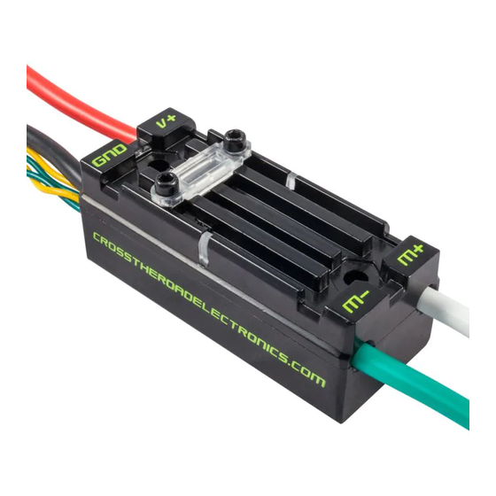
Note 1: This is based on the maximum quadrature edge-to-edge rating of 187.5ns. Note 2: A late errata on the microcontroller was released after Talon SRX 2015 season production, indicating the Quad B and Quad Idx are not 5V tolerant. As a result, Talons with revision 1.5 (and earlier) should not use sensor cable/breakouts that allow >3.6V on Quad B or Quad Idx, as this may damage Talon SRX. - Page 6 Green 22 AWG 11.0in [279.4mm] PWM Ground Note: There are (2X) yellow and (2X) green 22AWG signal wires on each Talon SRX. Signal wires of the same color are electrically identical. crosstheroadelectronics.com vexpro.com Copyright 2017, Cross The Road Electronics, VEX Robotics Inc.
-
Page 7: Installing A Talon Srx
PWM signal. In many cases, the output leads of the Talon SRX will not be long enough to reach the motor it is controlling, so an extension cable will be required. Extension cables should be made using appropriately sized wire and connected using tightly crimped connectors. -
Page 8: Wiring The Talon Srx Signal Input
The CAN bus capability of the Talon SRX is one of its most powerful features. It allows up to 63 Talon SRXs to be daisy chained – this means Talon SRXs can plug into each other and only require a single output on the primary robot controller. - Page 9 Talon SRX - User’s Guide Another option is to explicitly ensure each Talon SRX has a unique ID assigned to it prior to wiring the entire CAN bus harness. To do this, connect a yellow signal wire to the NI roboRIO CAN terminal marked “H”...
-
Page 10: Wiring The Talon Srx For Use With Can Bus
217-8080 Talon SRX - User’s Guide 1.3.2. Wiring the Talon SRX for use with CAN bus To wire CAN bus, connect a yellow signal wire to the CAN terminal marked “H” on the NI roboRIO and connect a green signal wire to the CAN terminal marked “L” on the NI roboRIO. - Page 11 Talon SRX - User’s Guide 1.3.2.1. CAN Connector The CAN Connector can be used to chain Talon SRX’s together without crimping connectors or soldering. Each CAN Connector contains a four channel Weidmuller terminal block with two CAN pairs (similar to other FRC CAN devices such as the Power Distribution Panel and Pneumatic Control Module).
-
Page 12: Wiring Talon Srx For Pwm Control
PWM connectors. (The NI roboRIO requires a female PWM connector.) Only (2X) of the (4X) signal wires are needed to control the Talon SRX with PWM. Do Not connect (2X) PWM connectors to a single Talon SRX. The (2X) wires that are not used for PWM control should be electrically isolated using tape or heat shrink tubing and neatly bundled out of the way to prevent damage. - Page 13 Connecting a Talon SRX to an NI roboRIO using PWM: To connect a Talon SRX to the NI roboRIO controller, simply plug the Talon SRX’s PWM cable into the desired PWM header in the roboRIO’s PWM output with the yellow (signal) wire on the “S” or “inside”...
-
Page 14: Firmware Requirements (Pwm And Can Bus)
Typically a Talon is shipped with firmware version 0.28. Teams should always check the FRC game rules to determine what is the required minimum firmware version for Talon SRX (PWM / CAN bus). Teams that utilize CAN bus will likely want to field-upgrade to the latest available firmware for the latest features and improvements (1.1 or newer). - Page 15 Talon can be done quickly with the following procedure... Power off robot and disconnect Talon SRX from roboRIO’s PWM port if it’s connected. Locate the free yellow/green CAN wire pair from the Talon. Since PWM-use only requires one yellow/green wire pair, the other should be free to use.
- Page 16 217-8080 Talon SRX - User’s Guide software does not require you to power cycle the robot before re-flashing each Talon, making wire changes while the robot is powered is a risk factor for shorting. Use best judgment on how to safely replace the upgraded Talon with the “next” Talon to field- upgrade.
-
Page 17: Wiring Sensors To The Talon Srx
1.4. Wiring Sensors to the Talon SRX 1.4.1. Data Port Pinout Sensors may be connected directly to the Talon SRX via the Data Port. The Talon SRX supplies the voltage and ground to the sensor devices. Do not supply external voltages or ground into the Data Port. -
Page 18: Analog Input
217-8080 Talon SRX - User’s Guide 1.4.2. Analog Input Attach the analog sensor as shown. Do not connect the GND line elsewhere. Only use 3.3V as the analog sensor voltage source. Although the figure explicitly shows a potentiometer, a 3.3V Analog Encoder can also be wired similarly. -
Page 19: Quadrature Encoder Input
217-8080 Talon SRX - User’s Guide 1.4.3. Quadrature Encoder Input Attach the Quadrature Encoder as shown. Do not ground the GND line elsewhere. Connect either the 3.3V or 5.0V as required by your sensor. DO NOT CONNECT THE 3.3V OUTPUT TO THE 5V OUTPUT. -
Page 20: Forward & Reverse Limit Switch Inputs
Attach the Forward/Reverse Limit Switch as shown. Do not connect the GND elsewhere. The Talon SRX provides a pull-up to 2.5v, so typically an external pull-up is not needed. Only use Talon SRX 3.3V or 5.0V power if an external pull-up is used. The default setting of “Normally Open” ensures an “out of the box”... - Page 21 217-8080 Talon SRX - User’s Guide +3.3V Analog Input Forward Limit Quadrature B DO NOT CONNECT Quadrature A Reverse Limit Quadrature Index Reverse Limit Switch - Normally Open (default) +3.3V Analog Input Forward Limit Quadrature B DO NOT CONNECT Quadrature A...
-
Page 22: Connecting To The Data Port
1.4.5. Connecting to the Data Port To maintain a sealed case, the Talon SRX includes a plastic cover for the Data Port. When the port is not being used, the plastic cover should be installed on the case, as shown below, to protect the pins from foreign objects. -
Page 23: Encoder (And Limit Switch) Breakout
The Encoder Breakout makes breaking out the encoder and limit switch pins even easier. Part Numbers: CTRE_ENC_BRK, 217-4398(vexrobotics.com), am-2633(andymark.com) The top side of the breakout has the same data port pinout as the Talon SRX. A ribbon cable should be used to connect the Talon SRX to the breakout. - Page 24 Talon SRX - User’s Guide 1.4.6.1. Encoder (and Limit Switch) Breakout – Blue Revision The latest revision of the Talon SRX Encoder Breakout Board has additional level shifting to ensure proper operation with 5V Quadrature sensors, regardless of Talon SRX hardware revision (see Electrical/Mechanical Specs –...
-
Page 25: Analog 5V Encoder (And Limit Switch) Breakout
5V Magnetic Shaft Encoders like the U.S. Digital MA3 “just work” since the breakout shifts the encoders native 5V output to a Talon SRX compliant 3.3V signal. The top side has the 5V power, signal, and ground pads for the analog sensor. -
Page 26: Heat Shrink Use With Breakout
217-8080 Talon SRX - User’s Guide 1.4.8. Heat Shrink Use with Breakout Another advantage to using the Quadrature or Analog Encoder Breakout is that they are designed to be encapsulated with large diameter heat shrink. This ensures that there is no risk of shorting the breakout to robot frame (or other conductive surfaces). -
Page 27: Mounting The Talon Srx
An important (yet frequently forgotten) aspect of wiring is strain relief. All electrical connections should be isolated from any pulling or tugging that may result in a poor connection. Once the Talon SRX is fully wired, zip ties should be used to ensure that all electrical connections are protected. -
Page 28: Applying Power For The First Time
All electrical connections are secure and electrically isolated (wrapped in electrical tape, heat shrink tubing or similar). A 40A or smaller breaker is in series with the Talon SRX’s positive power input. There are no short circuits on the Talon SRX’s output. -
Page 29: Additional Information
2.1. Brake & Coast Modes The Talon SRX has two modes: Brake and Coast. When a neutral signal is applied to the Talon SRX in Brake mode, the motor will resist rotation, especially high speed rotation. This is accomplished by essentially shorting the motor leads together, which causes a Back Electromotive Force (Back-EMF) to resist the rotation of the motor. -
Page 30: Pwm Calibration
Talon SRX - User’s Guide 2.2. PWM Calibration The PWM calibration of a Talon SRX determines how to scale the PWM input signal to output voltage. Different controllers may have different “max” and “min” PWM signals that may not correspond to the same Talon SRX outputs. -
Page 31: To Restore Default Calibration
1) Remove power from the Talon SRX 2) Hold the B/C CAL button down 3) While holding down the button, restore power to the Talon SRX 4) Continue holding the button until the status LEDs blink green then release the button crosstheroadelectronics.com... -
Page 32: Blink Codes
1: LEDs Alternate – Status LEDs are different colors at all times. The (2X) LEDs will swap colors when blinking. 2: (1X) Status LED will blink followed shortly by the other with a long pause before repeating. The “direction” of the blink indicates the Talon SRX’s current state. crosstheroadelectronics.com vexpro.com Copyright 2017, Cross The Road Electronics, VEX Robotics Inc. -
Page 33: Blink Codes - Damaged Hardware
IDs of the Talon SRX. Such LED patterns should not be misconstrued as the damaged LED code mentioned above. This is also supplemental content covered in the Talon SRX Software Reference Manual under Section 16 –... -
Page 34: Performance Data
Talon SRX - User’s Guide 2.4. Performance Data The Talon SRX was designed to provide a predictable linear response over a wide range of PWM signals. To demonstrate its linearity, an experiment was performed by using a calibrated Talon SRX controlled by a VEX Arm®... -
Page 35: Frequently Asked Questions
A: The Talon SRX does not require a fan for typical FRC use but if the robot is being used for practice or many back to back matches it is a good idea to use a fan to cool the Talon SRX to prevent accidental burns. - Page 36 217-8080 Talon SRX - User’s Guide Q: Will un-powering a Talon SRX in the middle of a daisy-chained CAN bus cause a problem? A: No. This does not prevent communication with the remaining Talons on the CAN bus. Both yellow wires are electrically-common, as is the green wires. Power is not required to forward the CAN signals.
- Page 37 217-8080 Talon SRX - User’s Guide Q: What CAN bus topologies are recommended? A: The Talon is intended to be used in the daisy chain fashion explained in Section 1.3.2. Additionally, FRC Teams should always confirm what is considered “legal” per latest FRC competition rules.
- Page 38 217-8080 Talon SRX - User’s Guide Star topology is not recommended. This use case is not common, nor is it suggested in the DW CAN bus specification. This nonstandard implementation requires careful study and analysis of the candidate bus cable, which is typically beyond the capabilities of a typical FRC team.
-
Page 39: Troubleshooting
Problem: The device is in Boot-loader Mode Solution: 1) Download the latest firmware from crosstheroadelectronics.com 2) Follow directions in the Software Reference Manual to field upgrade the Talon SRX. Indication: No LEDs are illuminated Problem: No Power Check the Following:... - Page 40 CAN control. Indication: Both LEDs slowly alternate between orange and off. Problem: CAN bus detected but the Talon SRX is disabled or not being addressed over CAN. Possible Solution: Use the roboRIO Web-based Configuration page to retrieve information over CAN bus about the fault.
- Page 41 Problem: Possible internal damage. Possible Solutions: If the Status LEDs on the Talon SRX are operating properly and there is no output, the Talon SRX may be internally damaged. This condition is typically caused by a short circuit on the output or there has been an over-current condition that caused a failure.
- Page 42 217-8080 Talon SRX - User’s Guide that neither of the Talon SRX’s motor output leads are shorted to motor frame or the robot chassis. crosstheroadelectronics.com vexpro.com Copyright 2017, Cross The Road Electronics, VEX Robotics Inc. Updated: 2017-02-03...
-
Page 43: Compliance
217-8080 Talon SRX - User’s Guide 4. Compliance FCC Compliance Statement (United States): This device complies with part 15 of the FCC Rules. Operation is subject to the following two conditions: (1) This device may not cause harmful interference, and (2) This device must accept any interference received, including interference that may cause undesired operation. -
Page 44: Revision History
217-8080 Talon SRX - User’s Guide 5. Revision History: 2017/2/3 – Added section 2.3.1. 2017/2/2 – Added errata under section 1.4.6.1. 2016/12/3 – Additional FAQ entries added for network topology. 2016/2/1 – Footnotes (1) and (2) added to Electrical /Mechanical specs.
Need help?
Do you have a question about the Talon SRX and is the answer not in the manual?
Questions and answers