Table of Contents
Advertisement
Berkeley-IPI
F R E E s t a n d i n g g a s F i R E P L a C E
OWNER'S MANUAL
WARNING:
If the information in this manual is not followed exactly, a
fire or explosion may result causing property damage, personal injury
or loss of life. Installation and service must be performed by a qualified
installer, service agency or the gas supplier.
4001609
50-3260
Version Française: www.enviro.com/fr.html
Advertisement
Table of Contents

Related Manuals for Enviro Berkeley-IPI


Summary of Contents for Enviro Berkeley-IPI
- Page 1 If the information in this manual is not followed exactly, a fire or explosion may result causing property damage, personal injury or loss of life. Installation and service must be performed by a qualified installer, service agency or the gas supplier. 4001609 50-3260 Version Française: www.enviro.com/fr.html...
-
Page 2: Safety Precautions
Safety Precautions WARNING: FIRE OR EXPLOSION HAZARD Failure to follow safety warnings exactly could result in serious injury, death, or property damage. - Do not store or use gasoline or other flammable vapors and liquids in the vicinity of this or any other appliance. - WHAT TO DO IF YOU SMELL GAS •... - Page 3 Safety Precautions FOR SAFE INSTALLATION AND OPERATION OF YOUR “ENVIRO” HEATER, PLEASE CAREFULLY READ THE FOLLOWING INFORMATION: • All ENVIRO gas-fired appliances must be installed in • A barrier designed to reduce the risk of burns from the accordance with their instructions. Carefully read all the hot veiwing glass is provided with this appliance and shall instructions in this manual first.
-
Page 4: Table Of Contents
Table of Contents Safety Precautions......................2 Table of Contents......................4 Codes And Approvals....................5 Specifications......................6 Dimensions.....................6 Rating Label Location..................6 Operating Instructions....................7 Lighting Instructions..................7 Air Shutter......................8 Normal Sounds During Operation................8 Transmitter.................9 Initializing the System for the First Time.............11 Switching to Continuous Pilot................11 Turn off the Appliance..................12 Room Thermostat....................12 Remote Flame Control..................12 Split Flow Operation..................13... -
Page 5: Codes And Approvals
After the unit has gone through the first burn, turn the unit off including the pilot, let the unit get cold then remove the glass door and clean it with a good gas fireplace glass cleaner, available at your local ENVIRO dealer. -
Page 6: Specifications
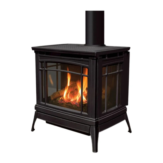
Specifications imensions 31 3/8" 30 1/4" [79.7 cm] [76.8 cm] 22 15/16" 29 5/16" [75.5 cm] [58.3 cm] 4 5/8" [11.7 cm] Figure 1. Berkeley Dimensions & L ating abeL ighting nstRuctions ocation The rating label and lighting instructions are located on a plate hanging on the back of of the unit. -
Page 7: Operating Instructions
Operating Instructions For Your Safety, Read Safety Precautions And Lighting Instructions Before Operating WARNING: IF YOU DO NOT FOLLOW THESE INSTRUCTIONS EXACTLY A FIRE OR EXPLOSION MAY RESULT, CAUSING PROPERTY DAMAGE, PERSONAL INJURY OF LOSS OF LIFE. ighting anD uRning nstRuctions FOR YOUR SAFETY READ BEFORE OPERATING WARNING:... -
Page 8: Air Shutter
Operating Instructions hutteRs Behind the valve access door is the air shutter adjustment levers on the right hand side of the venturi box (see Figure 4) above the control panel. The air shutters allow the amount of air coming into the fireplace to be adjusted in order to accommodate different climates and venting arrangements. -
Page 9: Transmitter
Operating Instructions ystem escRiption The Proflame 2 Remote Control System consists of two (2) elements: 1. Proflame 2 Transmitter. 2. Integrated Fireplace Controller (IFC) and a wiring harness to connect to the gas valve and stepper motor. ATTENTION! - TURN “OFF” THE MAIN GAS SUPPLY OF THE APPLIANCE DURING INSTALLATION OR MAINTENANCE OF THE IFC. - Page 10 Operating Instructions Key Lock Transmission Low battery alarm Thermostat OFF/ Room ON/SMART Temperature CPI mode Set Point Aux ON Temperature/Level/State Flame ON Split Flow Dimmer ON Comfort fan Figure 6: Proflame 2 Transmitter LCD Screen. (ifc): ntegRateD iRepLace ontRoLLeR The Proflame 2 IFC (Figure 7) connects directly to the gas valve, split flow valve, stepper motor, pilot and covection fan with a wiring harness.
-
Page 11: Initializing The System For The First Time
Operating Instructions peRating RoceDuRe Initializing The System For The First Time Install the four (4) AA batteries into the IFC battery holder. Note the polarity of the battery and insert into the battery bay as indicated on the body of the battery holder. Press the reset button on the IFC marked “SW1” (see Figure 7). The IFC will “beep”... -
Page 12: Turn Off The Appliance
Operating Instructions Turn off the Appliance Room Temperature Press the ON/OFF Key on the Transmitter. The Transmitter LCD display will only show the room temperature and Icon (see Figure 8). A single “beep” from the IFC confirms reception of the command and both the pilot light (if the unit is not set to continuous pilot) and main burner will turn off. -
Page 13: Split Flow Operation
Operating Instructions Split Flow Operation The split flow operation on the Berkeley turns off the front section of the burner, greatly reducing the heat output of the unit. If you’d like to have the fireplace on but would not like to have as much heat in the room, you can turn off this function. -
Page 14: Key Lock
Operating Instructions Key lock This function will lock the keys to avoid unsupervised operation. To activate this function, press the Mode and UP keys at the same time and the a lock will appear (see Figure 17). To de-activate this function, press the Mode and UP Keys at the same time. -
Page 15: Cleaning The Glass
The glass must be purchased from an ENVIRO dealer. No substitute materials are allowed. Remove the door (see page 16). The replacement glass will come with a new gasket installed. Remove any silicone remnants from the door. -
Page 16: Cast Door Removal
Maintenance And Service emovaL The cast door on the Berkeley needs to be removed whenever access to the firebox is required. First the Berkeley must be turned Cast Top off and allowed to fully cool. Next, remove the Cast Top as shown in Figure 21 by simply lifting up. -
Page 17: Burner Removal
Maintenance And Service uRneR emovaL The burner may need to be removed for a few reasons, including cleaning under the burner, converting the unit to a different gas type, or to replace the burner altogether. Proceed only when the unit has completely cooled down. -
Page 18: Fuel Conversion
Maintenance And Service onveRsion TO BE INSTALLED BY A QUALIFIED SERVICE AGENCY ONLY Please read and understand these instructions before installing. Warning: This conversion kit shall be installed by a qualified service agency in accordance with the manufacturer’s instructions and all applicable codes and requirements of the authority having jurisdiction. - Page 19 Maintenance And Service 6. Convert the burner orifices: a) Remove the main burner orifices with a 3/8” socket b) Put a bead of pipe-thread sealant into the orifice mount. DO NOT OVER-TIGHTEN c) Install new orifices. 7. Convert the SIT gas valve: a) Use a T-20 driver to remove the two screws that hold the servo regulator to the gas valve and disconnect the wire harness from the IFC.
-
Page 20: Initial Installation
Initial Installation QUALIFIED INSTALLERS ONLY ntRoDuction This section of the owner’s manual is for the use of qualified technicians only. Fireplace placement, hearths, and venting terminations will be covered, as well as the gas and electrical systems. There are several installation safety guidelines that must be adhered to. Please carefully read the safety precautions at the front of this manual. -
Page 21: Direct Vent
Initial Installation QUALIFIED INSTALLERS ONLY iRect WARNING: This appliance has been designed to draw room air for proper heat circulation from the bottom of the unit, and out the top front. Blocking or modifying these openings in any way can create hazardous situations. The vent length for the Berkeley must be between 36”... -
Page 22: Approved Venting Parts
Initial Installation QUALIFIED INSTALLERS ONLY ppRoveD enting aRts Table 3: Approved Vent Manufacturers Manufacturer Trade Name Nominal Sizes EXCELDirect 4” - 6 5/8” M&G DuraVent DirectVent Pro 4” - 6 5/8” The Berkeley fireplace has been tested and certified for use with M&G DuraVent DirectVent Pro and ICC EXCELDirect venting systems. -
Page 23: Horizontal Termination - Minimum Vent
Initial Installation QUALIFIED INSTALLERS ONLY oRizontaL eRmination inimum ength Refer to the figure for below for the minimum allowable venting setup for the Berkeley. A termination guard (50-3266) is required when the termination is within 7’ (2.13m) of grade. Approved horizontal termination Approved through wall thimble Termination... -
Page 24: Vent Termination Restrictions
Initial Installation QUALIFIED INSTALLERS ONLY eRmination estRictions Fixed Closed Fixed Openable Closed Openable Termination Cap Air Supply Inlet Gas Meter Restriction Zone (Termination not allowed) Figure 33. Vent Termination Restrictions, refer to Table 5. Table 5: Vent termination clearances. Letter Canadian Installation US Installation Description... -
Page 25: Allowable Vent Configurations
Initial Installation QUALIFIED INSTALLERS ONLY LLowabLe onfiguRations Figures 34 show the range of possible vent configurations for vertical and horizontal terminations. Any layout that remains within the shaded areas is acceptable. Having the fewest number of elbows is ideal, as they tend to disrupt air movement. Using 45˚ elbows is preferable to using 90˚ elbows. Also, a shorter vent system will perform better than a longer one. -
Page 26: Air Restrictor Settings
Initial Installation QUALIFIED INSTALLERS ONLY estRictoR When installing the Berkeley with 10ft (3.05m) or more of vertical venting it may be necessary to restrict the fresh air supply in the firebox to control the combustion and flame appearance. To install the air restrictor supplied with the uint the cabinet front and glass door must remove as outlined on page 12 in the m aIntenance section. -
Page 27: Horizontal Termination
Initial Installation QUALIFIED INSTALLERS ONLY oRizontaL eRmination NOTES: 1. Horizontal pipes must not be level. For every 12 inches (305 mm) of horizontal travel (away from the stove), there should be at least ¼ inch (6.4 mm) of vertical travel. Never allow the vent to run downward, as this could cause high temperatures or even present the possibility of a fire. -
Page 28: Vertical Termination
Initial Installation QUALIFIED INSTALLERS ONLY Step 4. With the hole now framed, the wall thimble installed, and the pipe extending into the wall, proceed to the outside. Attach the termination to the pipe using RTV and Mil-Pac or Rutland No 78 Stove and Gasket Cement to seal joints. - Page 29 Initial Installation QUALIFIED INSTALLERS ONLY STEP 5. Cut hole in the roof centered on the small hole placed in the roof from Step 2. The hole should be of sufficient size to meet minimum requirements for Clearance to Combustibles, as specified. Continue to assemble lengths of pipe and elbows necessary to reach from the ceiling support box up through the roof line.
- Page 30 Initial Installation QUALIFIED INSTALLERS ONLY NOTES: (1) If an offset is necessary in the attic to avoid obstructions, it is important to support the vent pipe every 3 feet (914 mm), to avoid excessive stress on the elbows, and possible separation. Wall straps are available for this purpose (see Figure 40).
-
Page 31: Gas Line Connection And Testing
Initial Installation QUALIFIED INSTALLERS ONLY onnection anD esting WARNING: Only persons licensed to work with gas piping may make the necessary gas connections to this appliance. GAS LINE CONNECTION • This stove is equipped with a certified flexible pipe located on the left side of the unit terminating in a 3/8”... -
Page 32: Electrical Requirements
Initial Installation QUALIFIED INSTALLERS ONLY LectRicaL equiRements The fireplace must be electrically connected and grounded in accordance with local codes or, in the absence of local codes, with the current CSA C22.1 Canadian Electrical Code Part 1, Safety Standards For Electrical Installations, or The National Electrical Code ANSI / NFPA 70 in the US. -
Page 33: Secondary Installation
Secondary Installation nstaLLation The placement of the logs is not arbitrary. If they are positioned incorrectly, the flames can be “pinched” and will not burn correctly. All of the logs come with either a notch or ledge, which make alignment easier. Using the pictures provided, carefully set the logs in place (see Figures 44 through 50). - Page 34 Secondary Installation 5. Install the front three ember bed logs as shown in Figure 47. Note the locating notches on the backside of the logs. The depressions in the ember bed only allow the logs to be installed one way. Figure 47.
- Page 35 A small amount on the bottom side of the logs is normal. Remove and replace the logs in the same manner described above. If new logs are required, contact your nearest ENVIRO dealer. Never operate the fireplace with the glass door removed.
-
Page 36: Safety Screen Replacement
Secondary Installation afety cReen epLacement The Berkeley is supplied with safety screens already installed on the back of the cast front and sides. If a safety screen becomes damaged must it be replaced with either part number 50-3243 (front) or 50-3244 (side) by following the steps below: Front Screen Side Screen... -
Page 37: Trouble Shooting
Trouble Shooting iagnostic Lash oDes 1. Fail to ignite: If there is no positive ignition, the board will go into lock out and the LED will blink 3 times in intervals until the system is reset. 2. Low battery condition (<4V): the LED indicator will blink one (1) time in intervals. 3. - Page 38 Trouble Shooting Problem Possible Cause Solution The pilot flame has gone out Thermostat · Turn it ON does not The On/Off switch is turn to OFF work The thermostat is set too high · Set the thermostat to a lower temperature ·...
- Page 39 Trouble Shooting Problem Possible Cause Solution · Turn the system off by pressing the ON/OFF button on the transmitter · After approximately 2 seconds press the ON/OFF button on the transmitter again. · In the manual flame control mode, use the down arrow button to reduce the flame to off, indicated by the word OFF displayed on the transmitter LCD screen.
-
Page 40: Parts List
Replacement Safety Screen - Side 50-3244 Vent Collar Cover 50-3245 Termination Guard 50-3266 Berkeley-IPI Owners Manual 50-3260 Conversion Kit - LP to NG (IPI) 50-3263 Conversion Kit - NG to LP (IPI) 50-3264 12 oz. Can of Matallic Black Touch Up Paint... - Page 41 Parts List...
- Page 42 Parts List Reference Part Description Part Number Number Cast Top - Painted 50-3246 Cast Top - Enameled Antique Chestnut 50-3247 Cast Front - Painted 50-3248 Cast Front - Enameled Antique Chestnut 50-3249 Cast Skirt - Painted 50-3250 Cast Skirt - Enameled Antique Chestnut 50-3251 Cast Right Side - Painted 50-3252...
-
Page 43: Warranty
Exclusions conditions herein set forth, this product against defects in material and workmanship An expanded list of exclusions is available at www.enviro.com/help/warranty.html during the specified warranty period starting from the date of original purchase at retail. This warranty does not cover: In the event of a defect of material or workmanship during the specified warranty period, ƒ... -
Page 44: Installation Data Sheet
� NATURAL GAS (NAT) PROPANE(LPG) _________________________________________ INLET GAS PRESSURE:_________in wc PHONE:___________________________________ MAIN BURNER ORIFICE:__________# DMS PILOT ORIFICE #_________OR________in diam. INSTALLER’S SIGNATURE: _________________________________________ MANUFACTURED BY: SHERWOOD INDUSTRIES LTD. 6782 OLDFIELD RD. SAANICHTON, BC, CANADA V8M 2A3 www.enviro.com July 8, 2016 C-14873...
Need help?
Do you have a question about the Berkeley-IPI and is the answer not in the manual?
Questions and answers