YOKOGAWA FLXA21 User Manual
2-wire analyzer
Hide thumbs
Also See for FLXA21:
- User manual (64 pages) ,
- Startup manual (35 pages) ,
- Technical information (24 pages)

Related Manuals for YOKOGAWA FLXA21


Summary of Contents for YOKOGAWA FLXA21
- Page 1 User’s Manual Model FLXA202 / FLXA21 2-Wire Analyzer IM 12A01A02-01E IM 12A01A02-01E 8th Edition...
- Page 2 • No part of the user’s manuals may be transferred or reproduced without prior written consent from YOKOGAWA. • YOKOGAWA reserves the right to make improvements in the user’s manuals and product at any time, without notice or obligation. • If you have any questions, or you find mistakes or omissions in the user’s manuals, please contact our sales representative or your local distributor.
- Page 3 The model FLXA202/FLXA21 2-Wire Analyzer offers 4 kinds of measurements – pH/ORP (oxidation-reduction potential), contacting conductivity (SC), inductive conductivity (ISC) or dissolved oxygen (DO) – with a respective sensor module. The FLXA202/FLXA21 delivered has one specific kind of measurement depending on your order. Contacting Inductive...
- Page 4 The product is provided on an “as is” basis. YOKOGAWA shall have neither liability nor responsibility to any person or entity with respect to any direct or indirect loss or damage arising from using the product or any defect of the product that YOKOGAWA can not predict in advance. IM 12A01A02-01E...
- Page 5 Mark position of intrinsic safety The mark position of intrinsic safety is shown as follows FLXA202-D-*-… Type:-CB This marking conforms to Intrinsic safety of IECEx. This marking conforms to Intrinsic safety of ATEX. IM 12A01A02-01E 8th Edition : Oct. 01, 2015-00...
-
Page 6: Bottom Side
FLXA21-D-*-… -P (Plastic) -S (Stainless steel) -U (Stainless steel + urethane coating) -E (Stainless steel + epoxy coating) This marking conforms to Intrinsic safety of IECEx. This marking conforms to Intrinsic safety of ATEX. This marking conforms to Intrinsic safety of NEPSI. - Page 7 FLXA202/FLXA21 • The FLXA202/FLXA21 should only be used with equipment that meets the relevant IEC, American, Canadian, and Japanese standards. Yokogawa accepts no responsibility for the misuse of this unit. • Don’t install “general purpose type” instruments in the hazardous area.
- Page 8 Electrostatic charge may cause an explosion hazard. Avoid any actions that cause the generation of electrostatic charge, e.g., rubbing with a dry cloth. Because the enclosure of the FLXA21 2-Wire Analyzer, if it is mounted in an area where the use of category 1 G Zone 0 apparatus is required, it must be installed such, that, even in the event of rare incidents, ignition sources due to friction sparks are excluded.
- Page 9 Material safety data sheets should also be included for all components of the processes to which the equipment has been exposed. Authorised Representative in EEA The Authorised Representative for this product in EEA is Yokogawa Europe B.V. (Euroweg 2, 3825 HD Amersfoort, The Netherlands). Copyright and Trademark Notices The copyrights of online manual contained in the CD-ROM are reserved.
- Page 10 FLXA202/FLXA21’s fonts (c) Copyright 2000-2001 /efont/ The Electronic Font Open Laboratory. All rights reserved. Redistribution and use in source and binary forms, with or without modification, are permitted provided that the following conditions are met: 1. Redistributions of source code must retain the above copyright notice, this list of conditions and the following disclaimer.
-
Page 11: Table Of Contents
Toc-1 Model FLXA202 / FLXA21 2-Wire Analyzer IM 12A01A02-01E 8th Edition CONTENTS Introduction ....................i Safety Precautions ..................iii INTRODUCTION AND GENERAL DESCRIPTION ........1-1 Instrument check ....................1-3 Screen operation ....................1-5 Passwords ....................... 1-10 Regulatory Compliance .................. 1-10 WIRING AND INSTALLATION ..............2-1 Installation site .................... - Page 12 Toc-2 4.2.1 Measurement ..................4-3 4.2.2 Temperature settings ................. 4-4 4.2.3 Temperature compensation ............... 4-4 4.2.4 Calibration settings ................4-5 4.2.5 Impedance settings ................4-8 4.2.6 Concentration ..................4-8 4.2.7 Sensor diagnostic settings ..............4-9 Output setup ...................... 4-9 Error configuration ..................4-11 Logbook configuration ...................
- Page 13 Toc-3 Measurement setup ..................7-3 7.1.1 Measurement ..................7-3 7.1.2 Configure sensor................7-3 7.1.3 Temperature settings ................. 7-3 7.1.4 Temperature compensation ............... 7-4 7.1.5 Calibration settings ................7-5 7.1.6 Concentration ..................7-5 7.1.7 Sensor diagnostic settings ..............7-6 Output setup ...................... 7-6 Error configuration ...................
- Page 14 Toc-4 COMMISSIONING OF ISC (Inductive Conductivity) ......10-1 10.1 Measurement setup ..................10-2 10.1.1 Measurement ................... 10-3 10.1.2 Configure sensor................10-3 10.1.3 Temperature settings ............... 10-3 10.1.4 Temperature compensation ............. 10-3 10.1.5 Calibration settings ................10-4 10.1.6 Concentration ................... 10-5 10.1.7 Sensor diagnostic settings ...............
- Page 15 Toc-5 13.1 Sensor setup ....................13-2 13.2 Measurement setup ..................13-3 13.2.1 Sensor setup ..................13-3 13.2.2 Temperature settings ............... 13-3 13.2.3 Temperature compensation ............. 13-3 13.2.4 Salinity compensation ..............13-3 13.2.5 Pressure comp. (Measure) .............. 13-3 13.2.6 Calibration settings ................13-4 13.2.7 Sensor diag.
- Page 16 Toc-6 16.1 Sensor setup ....................16-3 16.2 Measurement setup ..................16-4 16.2.1 Measurement ................... 16-4 16.2.2 Temperature settings ............... 16-4 16.2.3 Temperature compensation ............. 16-4 16.2.4 Calibration settings ................16-6 16.2.5 Impedance settings ................16-9 16.2.6 Concentration ................... 16-9 16.2.7 Sensor diagnostic settings ...............
-
Page 17: Introduction
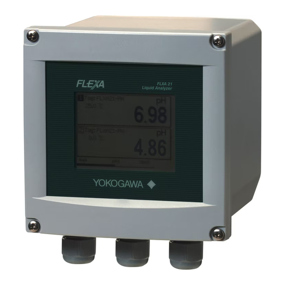
<1. INTRODUCTION AND GENERAL DESCRIPTION> INTRODUCTION AND GENERAL DESCRIPTION This manual describes how to use the FLXA202/FLXA21 with Yokogawa’s or other companies’ sensors. Please read carefully this manual and the instruction manual of the relevant sensor before using this instrument. - Page 18 (Do not use it) Slide switch (for HART only) Terminal block for power supply Nameplate Cable entry holes Front view with all wiring covers removed Figure 1.2 FLXA21 Parts names and descriptions IM 12A01A02-01E 8th Edition : Oct. 01, 2015-00...
-
Page 19: Instrument Check
Inside of the FLXA202 and example of nameplate FLXA21 Loosen four front panel screws of the FLXA21, open the panel to the left, and make sure the model and suffix code on the nameplate affixed to the back side of the front panel agrees with your order. - Page 20 <1. INTRODUCTION AND GENERAL DESCRIPTION> -D-P-S-AA-P1-NN-AN-L1N-NN /UM/SCT/H6 S1.01 J312FA012 2012.01 Figure 1.4 Inside of the FLXA21 and example of nameplate Checking the accessories Make sure the accessories in Table 1.1 are included. Table 1.1 Accessories Product Name Quantity Remark Cable glands FLXA202 3 sets One rubber plug attachement.
-
Page 21: Screen Operation
<1. INTRODUCTION AND GENERAL DESCRIPTION> Table 1.2 Production year code Year Year code Year Year code Year Year code Year Year code 2010 2015 2020 2025 2011 2016 2021 2026 2012 2017 2022 2027 2013 2018 2023 2028 2014 2019 2024 2029 Table 1.3... -
Page 22: Section 5 Section
<1. INTRODUCTION AND GENERAL DESCRIPTION> Monitor display 10.38 Figure 1.5 Example of monitor display Monitor display The Monitor display appears upon startup when the MONITOR display is enabled. When the measurement value (primary value) on the main or home display is pressed, the monitor display appears. - Page 23 <1. INTRODUCTION AND GENERAL DESCRIPTION> NOTE Measurement values on the display can be set independent of the process parameter. Calculated data Redundant sys. 0.03 10.38 Differential Sensor Sensor Sensor Sensor Diff-pH 20mA 20mA Figure 1.7 Example of calculated date and redundant system Home display (when two sensors are connected) Tag:PH 10.38...
- Page 24 <1. INTRODUCTION AND GENERAL DESCRIPTION> Zoom display HOLD FAIL WASH 15.00 Next Next Figure 1.10 Example zoom display The zoom display appears when the Zoom button on the main display is pressed. The Zoom display shows an easy-to-read graphical display of the output status. Pressing Next displays the contact state if communication is set to PH201G distributor.
-
Page 25: Maintenance
<1. INTRODUCTION AND GENERAL DESCRIPTION> Information button Diagnosis information on converters and sensors appears. No malfunction detected. Warning When a warning icon appears, maintenance is required. Pressing this icon displays an error message, and pressing the message displays the troubleshooting guidelines. Fault This icon indicates a malfunction. -
Page 26: Passwords
1-10 <1. INTRODUCTION AND GENERAL DESCRIPTION> Passwords Passwords can protect the FLXA202/FLXA21 from other persons’ access except a right operator’s. Execute &Setup Commissioning Advanced setup Passwords Execute: Sensor setup Settings Execute: Calibration/Wash Measurement setup HOLD Output setup Passwords Commissioning: Temporary output... - Page 27 0.45 mH Specific Conditions of Use When the enclosure of FLXA21/202 Analyzer is made of aluminum alloy, and when it is used in an explosive atmosphere requiring equipment of Category 1 G or EPL Ga, the Analyzer must be installed in such a way that, even in the event of rare incidents, an ignition SENCOM source due to impact friction sparks is excluded.
- Page 28 1-12 <1. INTRODUCTION AND GENERAL DESCRIPTION> FLXA21 Intrinsic safety and nonincendive (suffix code Type : -EA, -ES): ATEX Intrinsic safety approval Applicable standard Explosive Atmospheres EN 60079-0: 2012/A11: 2013 Equipment - General requirements EN 60079-11: 2012 Equipment protection by Intrinsic safety “i”...
- Page 29 1-13 <1. INTRODUCTION AND GENERAL DESCRIPTION> C22.2 No213-M1987 Non-incendive Electrical Equipment for Use in Class I, Division 2 Hazardous Locations CAN/CSA-E60079-0-07 Electrical apparatus for explosive gas atmospheres - Part 0: General requirements CAN/CSA-E60079-11-02 Electrical apparatus for explosive gas atmospheres - Part 11: Intrinsic safety “i” IEC 60529:2001 Degrees of protection provided by enclosures (IP Code) Type of protection (C22.2)
- Page 30 1-14 <1. INTRODUCTION AND GENERAL DESCRIPTION> pH/ORP Sensor module, SC Sensor module and DO Sensor module Input parameters Ui, Vmax = 13.92 V Ii, Imax = 50 mA Pi, Pmax = 0.374 W = 40 nF = 2.9 mH Output parameters Sensor input circuit(pH: terminals 11 through 19, SC: terminals 11 through 16, DO: terminals 11 through 18) Uo Vt, Voc...
- Page 31 1-15 <1. INTRODUCTION AND GENERAL DESCRIPTION> ATEX and IECEx Control Drawing (for 4-20mA type) Hazardous Location ← → Non Hazardous Location Measuring module 1 Supply + Sensor 1 Safety Barrier Housing Assembly (Note 1) Supply - Measuring module 2 Sensor 2 Note: The measuring module on this drawing means the sensor module on this General Specifications.
- Page 32 Note 10: As an alternative to installing the FLXA21 in Division 2 using Class I, Division 2 wiring methods, the FLXA21 may be installed in Division 2 using nonincendive field wiring in accordance with the National Electrical Code (NFPA 70) using the same parameters identified for intrinsically safe entity installations.
-
Page 33: Installation And Wiring
When measuring inductive conductivity, only one module can be installed. WARNING Installation and wiring The FLXA202/FLXA21 should only be used with equipment that meets the relevant IEC, American or Canadian standards. Yokogawa accepts no responsibility for the misuse of this unit. IM 12A01A02-01E... - Page 34 CAUTION The HART communication may be influenced by strong electromagnetic field. In this case another trial of the HART communication and/or operation with FLXA202/FLXA21 touch screen can be carried out. WARNING • Do not use an abrasive or organic solvent in cleaning the instrument.
- Page 35 <1. INTRODUCTION AND GENERAL DESCRIPTION> WARNING Electrostatic discharge The FLXA202/FLXA21 contains devices that can be damaged by electrostatic discharge. When servicing this equipment, please observe proper procedures to prevent such damage. Replacement components should be shipped in conductive packaging. Repair work should be done at grounded workstations using grounded soldering irons and wrist straps to avoid electrostatic discharge.
-
Page 36: Wiring And Installation
<2. WIRING AND INSTALLATION> WIRING AND INSTALLATION Install the cable glands into the FLXA202/FLXA21 before installing it (see section 2.3.) Upon delivery, the cable glands are not installed. WTB10 or BA10 Case of Distributor FLXA202 2-Wire Analyzer Terminal box PH201G (Style B) –... -
Page 37: Section 11 Section
<2. WIRING AND INSTALLATION> WTB10 or BA10 Case of Distributor FLXA21 2-Wire Analyzer Terminal box PH201G (Style B) – CMN CMN n n n n n n n Output 2 (1-5V DC) (*3) n n n n n n n n n... -
Page 38: Installation Site
<2. WIRING AND INSTALLATION> Installation site The FLXA202/FLXA21 is weatherproof and can be installed both inside and outside. It should, however, be installed as close as possible to the sensor to avoid long cable runs between the instrument and sensor. When the pH sensor is used, the cable length including the sensor cable should not exceed 20 meters (65.6 feet);... -
Page 39: Removing The Wiring Cover
Be careful not to lose the wiring cover screws. Wiring cover 1 Wiring cover 2 Wiring cover 3 (for the first module) (for the second module) (for the power supply and grounding) Figure 2.4 FLXA21 Wiring cover IM 12A01A02-01E 8th Edition : Oct. 01, 2015-00... -
Page 40: Installing The Cable Glands
(A hole is drilled, if specified.) For power supply For power supply For grounding cable (Functional ground) FLXA21 Plastic Housing FLXA21 Stainless Steel Housing F0202.ai Figure 2.5 Cable gland diagram CAUTION Be careful not to be injured by the sharp hole edges on the housing. - Page 41 Sleeve (for grounding cable line of the plastic housing) Rubber plug (without wiring) FLXA21 Plastic Housing FLXA21 Stainless Steel Housing F0203.ai Figure 2.6 Cable glands The unused cable glands should be sealed with the supplied close up plug. CAUTION When installing cable glands, hold cable glands and tighten cable gland nuts to a torque of 6 N•m.
-
Page 42: Wiring The Power Supply
Two (2) Sensor modules (2 inputs): 22.8 to 40V DC (for pH/ORP, SC and DO) Note: When the FLXA202/FLXA21 is used in the multi-drop mode of HART communication, the output signal is changed from 12.5 mA DC to 4 mA DC just after the power is turned on. Enough power supply for the instruments is to be provided. -
Page 43: Grounding
<2. WIRING AND INSTALLATION> CAUTION The FLXA202/FLXA21 is used with a DC power supply. Do not use an alternating current or 100 volt mains power supply. The cable leading to the distributor (power supply) supplies the power to and transmits the output signal from the FLXA202/FLXA21. -
Page 44: Connection Of The Power Supply
<2. WIRING AND INSTALLATION> Grounding the FLXA21 stainless steel housing Use the terminal outside the converter housing for grounding (Figure 2.9C). Use a ring terminal. When connecting the converter to a distributor, connect the shield of a double-core shielded cable to the terminal on the terminal block in the converter. -
Page 45: Wiring Cover
Wiring covers are required intrinsic safety (Type is -C*). In the case of other types, the cover is not attached to the FLXA202. FLXA21 After grounding and connecting the power supply, check the wiring and then close the wiring cover 3 (Figure 2.4). -
Page 46: Sensor Wiring
2-11 <2. WIRING AND INSTALLATION> Sensor wiring The FLXA202/FLXA21 can be used with a wide range of commercially available sensor types, both from Yokogawa and other manufacturers. Terminal screw size is M4, and torque of screw up is 1.2 N•m. - Page 47 Unlock Figure 2.12 Locking the module When all sensor wiring is completed, close the front panel of the FLXA21, and turn on the power. Make sure that the display is normal. CAUTION Do not tighten up four front panel screws one by one.
- Page 48 2-13 <2. WIRING AND INSTALLATION> Wiring of YOKOGAWA sensors Board Terminals Input 2Input 1 Sensor Measurement Jumper Remark 18/13 19/15 DO30G Fixed Cable FU20/ pH, pH & PH20/ Fixed Cable ORP, rH FU24 FU20/ PH20/ 13/14 Fixed Cable FU24 FU20/ pH Comp.
- Page 49 2-14 <2. WIRING AND INSTALLATION> Wiring of HAMILTON sensors Board Terminals Input 2 Input 1 Measure- Sensor Jumper Remark ment 18/13 19/15 WU20D CHEMTRODE Blue (White) 13/14 Cable CHEMTRODE- Yes 13/14 CHEMTRODE- 13/14 VP6-SC WU20D CLARITRODE Blue (White) 13/14 Cable CLARITRODE- VP6-SC White/...
-
Page 50: Wiring The Ph/Orp Sensor
2-15 <2. WIRING AND INSTALLATION> 2.5.1 Wiring the pH/ORP sensor pH Measurement Conventional pH sensors are connected to the module as follows: FLXA202/FLXA21 11 Temperature 12 Temperature 13 Reference 14 Solution ground 15 Glass (measure) 16 Shield 17 Shield Liquid... - Page 51 ORP as process variable and a pH Glass electrode as reference. This is the case with rH measurement and with pH compensated ORP measurement. Conventional ORP sensors are connected to the module as follows: FLXA202/FLXA21 11 Temperature 12 Temperature...
- Page 52 <2. WIRING AND INSTALLATION> NOTE The special grommet is intended to be used to seal the multiple cables from the Yokogawa flow fittings such as FF20. The designated cables are WU20 sensor cables, which are approximately 5 mm (0.2”) in diameter, and K1500FV liquid earth cables, which are approximately 2.5 mm (0.1”) in diameter.
-
Page 53: Wiring The Conductivity (Sc) Sensor
2.5.2 Wiring the conductivity (SC) sensor Contacting Conductivity, SC, sensors are connected to the module as follows: FLXA202/FLXA21 Temp The above diagram shows wiring for 4-electrode conductivity sensors, such as SC42-SP34 large bore series. For 2-electrode conductivity sensors, such as SC42-SP36 small bore series, jumpers must be installed between terminals 13-14 and between terminals 15-16, as shown in the diagram below. -
Page 54: Wiring The Dissolved Oxygen (Do) Sensor
The input module for DO measurement is suitable for different types of DO sensors: i. Galvanic sensors like model DO30G ii. Polarographic sensors like HAMILTON’S Oxyferm and Oxygold The connection is as follows: FLXA202/FLXA21 11 TC + TC - + anode galvanic... -
Page 55: Mounting Methods
* Tighten the four screws to a torque of 2 N·m. Figure 2.15 Three types of mounting with the optional mounting hardware See General Specifications (GS 12A01A02-01E) for the dimensions of the FLXA202/FLXA21 and mounting hardware. IM 12A01A02-01E 8th Edition : Oct. 01, 2015-00... -
Page 56: Operation
SENCOM A sheet for user settings is contained in the CD-ROM. Please take a memo of your settings on it when you configure the FLXA202/FLXA21 and keep the sheet just in case. IM 12A01A02-01E 8th Edition : Oct. 01, 2015-00... -
Page 57: Operation Of Ph/Orp
<3. OPERATION OF pH/ORP> OPERATION OF pH/ORP This chapter describes the screen operations of pH/ORP, the object to be measured. Further details of screen operations can also be found in section 1.2. Tag:PH 10.38 25.0 °C Calibration 19 mV ◆pH Calibration pH 20mA ◆Manual... -
Page 58: Change Language
<3. OPERATION OF pH/ORP> Change language The screen is set to display English at factory shipment; if you wish to use the FLXA202/FLXA21 in another language, first select a language as described in section 2.7. Quick setup The Quick setup screen is used to set up the basic items you want to set up first, such as the date/time and sensor settings. - Page 59 <3. OPERATION OF pH/ORP> Sensor setup mA(output) Quick setup Sensor type pH+ORP Process parameter Start quick setup? Temperature1 ORP1 pH+ORP 0% value 0.00 pH Chanage language Temperature2 100% value 14.00pH ORP2 Next Finish Next Finish Date/Time Measurement setup Monitor display Format YYYY/MM/DD Measurement...
-
Page 60: Home Display, Main Display And Monitor Display
<3. OPERATION OF pH/ORP> Measurement setup Select a suitable measurement parameter from among those displayed and set it up. Measurement parameter setup can be made only when “pH + ORP” is selected on the Sensor setup screen. For details, see section 4.2.1. Temperature settings Select a suitable temperature element from among those displayed and set it up. -
Page 61: Zooming In On Details
<3. OPERATION OF pH/ORP> On the Home display, pressing of the 1st sensor (top) or 2nd sensor (bottom) causes the display of the selected sensor to appear on the Main display. On the Main display, pressing of the 2nd or 3rd display item causes the 1st display item to be replaced by the selected item. - Page 62 <3. OPERATION OF pH/ORP> In case of trouble, when you contact your nearest Yokogawa service center, please inform us of the module and FLXA202/FLXA21 software revision displayed on the Detail screen and other display information as well as the module productions number indicated on the nameplate attached to the instrument.
- Page 63 For an ORP sensor, “Impedance” shows electrical resistance of metal electrode. The FLXA202/FLXA21 checks the impedance to know the surface condition of smudge and the snapping of sensor wires. In case of “Input Impedance setting” is “High” and the measured input-1 impedance value is higher than 100 kΩ, the display shows “MΩ...
- Page 64 <3. OPERATION OF pH/ORP> If both impedance measurements are disabled (Error setting: Off), the display shows “- - - - (bar)”. If either impedance measurement 1 or 2 is enabled, the display shows both the impedance values. Impedance 2 Impedance shows the electrical resistance of the reference electrode liquid junction. The liquid junction forms the electrolytic contact between the reference electrode and the measuring electrode, so it must be kept clean and filled with conductive electrolyte.
- Page 65 Read logbook The FLXA202/FLXA21 has two types of logbook per sensor to store history information on events, such as changed settings and calibrations. By selecting one of the logbooks that you wish to check, you can retrieve and check this information.
-
Page 66: Trend Graphics
SETUP” menu (Section 4.7.2). The screen displays the trend of up to 41 averages of the measurement for each time interval. The FLXA202/FLXA21 samples the measurements every second. The trending graphic also shows the maximum and minimum measured values in that interval. -
Page 67: Instrument Status Screen
3-11 <3. OPERATION OF pH/ORP> NOTE Updating the trend screen setup resets the current trend graph and starts a new one. Tag: PH 10.38pH 12.00 Max. and min. values on this display Current process value 8.40 5.60 Maximum Average 2.50 Minimum 12:00 12:20... -
Page 68: Calibration And Commissioning
3-12 <3. OPERATION OF pH/ORP> Calibration and Commissioning Allows you to calibrate and configure the instrument. These operations can be protected with a password. For details on the password, refer to section 4.6.3. Execute & Setup Execute: Calibration HOLD Temporary output Setup: Commissioning Change language... -
Page 69: Commissioning Of Ph/Orp
<4. COMMISSIONING OF pH/ORP> COMMISSIONING OF pH/ORP This chapter describes how to check and change settings from the Commissioning screen. When you move to the Commissioning screen, the output is held. Execute &Setup Commissioning Execute: Sensor setup Calibration/Wash Measurement setup HOLD Output setup Temporary output... - Page 70 <4. COMMISSIONING OF pH/ORP> Table 4.1 Menu Structure and Default Values in “Commissioning” Parameter Ref. sect. Sensor setup Sensor type Measurement setup Measurement 4.2.1 Temperature setting Temp. element 4.2.2 Temp. compensation Compensation 4.2.3 Reference temp. Process Temp. Compensation Calibration settings pH settings Zero and Slope units 4.2.4...
-
Page 71: Sensor Setup
<4. COMMISSIONING OF pH/ORP> Sensor setup “Sensor type” setup is determined by the sensor to be connected to the instrument. Select one of the following three sensor types: Only pH is measured. The glass electrode (input 1) is connected to terminal 15 and the reference electrode (input 2) is connected to terminal 13. -
Page 72: Temperature Settings
<4. COMMISSIONING OF pH/ORP> 4.2.2 Temperature settings Select the temperature element used for compensation from among Pt1000, Pt100, 3kBalco, 8k55, PTC10k, 6k8, and 500Ω. Select the same type as the temperature element that is actually connected. Celsius (°C) or Fahrenheit (°F) temperature units are available. If the unit is changed, the following values are also recalculated automatically to the new unit: •... -
Page 73: Calibration Settings
<4. COMMISSIONING OF pH/ORP> Matrix Matrix means a temperature compensation which uses the temperature compensation matrix. The temperature compensation matrix is a table of pH values at various temperatures corresponding to the pH values at the standard temperature. For details, see Appendix 1. When the temperature or the precompensated pH value is out of the range of the temperature compensation matrix, the temperature compensation error (warning) will be issued. - Page 74 These data can be obtained from the manufacturer of the probe, by the users laboratory, etc. NOTE It is not necessary to enter this data. In most cases, as the FLXA202/FLXA21 automatically does this while performing calibration, the feature is used in the case of special electrode systems or where calibration in the process environment is not possible.
- Page 75 <4. COMMISSIONING OF pH/ORP> Auto correct (Zero, Slope) This function calculates calibration coefficients from the transition of past calibration data (zero, slope) and compensates pH value using these calibration coefficients after the latest calibration. The default setting is “Disable.” To make the function effective, select “Enable.” a: Actual change b: Zero and slope calculated from the calibration data...
-
Page 76: Impedance Settings
The FLXA202/FLXA21 has an impedance check, which is capable of monitoring the impedance of various sensor systems. In order to “fine tune” this diagnostic tool, it is necessary to set it up to match the sensors used. -
Page 77: Sensor Diagnostic Settings
<4. COMMISSIONING OF pH/ORP> 4.2.7 Sensor diagnostic settings This screen is used to set items relating to sensor diagnostics displayed on the screens invoked by pressing Gauges are displayed for only parameters that have been enabled in “Sensor diag. settings.” Parameters set to Disable are provided with a bar display. - Page 78 4-10 <4. COMMISSIONING OF pH/ORP> <Redundant system> On the Redundant system, when a sensor (Sensor 1) of the 1st module fails, the output is automatically switched to the output of the 2nd module. After repairing the Sensor 1, manual reset of redundant system is necessary to return to the output of 1st module from the output of the 2nd module.
-
Page 79: Error Configuration
4-11 <4. COMMISSIONING OF pH/ORP> Configure Hold On the Configure Hold, settings are performed to hold of the mA output at a preset value. (Refer to the section 5.4.) This is enabled only if “mA” is “Output.” During the Commissioning or the Quick Setup, the mA output is automatically held. The preset value depends on a setting on the “Last or fixed”. - Page 80 4-12 <4. COMMISSIONING OF pH/ORP> Table 4.2 Error configuration Display item Description Default pH too high The pH value exceeds 16.00. Warn. pH too low The pH value is lower than –2.00. Warn. Temperature too high Measured process temperature is higher than the Warn.
-
Page 81: Logbook Configuration
4-13 <4. COMMISSIONING OF pH/ORP> Logbook configuration In “Logbook configuration,” the user configures information to be saved to a logbook or initializes the logbooks. Logbooks are used to keep an electronic record of events such as error messages, calibrations, and programmed data changes. By referring to this log, users can, for instance, easily determine maintenance or replacement schedules. -
Page 82: Tag
A tag provides a symbolic reference to an instrument and is generally defined to be unique throughout the control system at one plant site. A tag can contain up to 12 alphanumeric characters. The default value is PH or FLXA21-PH. When two sensor modules are installed, each module can have their own tag numbers. - Page 83 4-15 <4. COMMISSIONING OF pH/ORP> HART Select this menu when HART communication is made. In the HART setup screen, specify the network address and set up parameters for SV, TV, and (PV is linked with the “process parameter” setting in “Output settings” and cannot be changed here.) Network address For 1-to-1 communication, leave the default value [0] unchanged.
- Page 84 4-16 <4. COMMISSIONING OF pH/ORP> Wash contact Select Disabled or Enabled. When this item is enabled, items for a wash can be set on the Wash settings screen. In the Wash settings screen, set the interval time, wash time, and recovery time and setup of various washes.
-
Page 85: Factory Setup
4-17 <4. COMMISSIONING OF pH/ORP> However, for applications where the pH during wash shows almost the same value as the normal pH, the difference will be approximately zero. In such a case, disable the wash recovery check. An example of such applications is the monitoring of waste water pH. If you select water jet cleaning in such a case, the normal pH as well as the washing time pH will be around pH 7;... -
Page 86: Main Display (Dual Display, Individual Display)
4-18 <4. COMMISSIONING OF pH/ORP> 4.7.1 Main display (Dual display, Individual display) Display setup Display setup Dual display Main display Trend Individual display Trend Auto Return Auto Return Ad.just contrast Adjust contrast MONITOR display MONITOR display Figure 4.7 Display setup screens for a single module (left) and two modules (right) Main display When one module is installed on the instrument, only the Main display is available. -
Page 87: Trend
4-19 <4. COMMISSIONING OF pH/ORP> 4.7.2 Trend This screen is used to make settings for the Trend Graph Screen. Set the process parameters to be displayed for each trend. They can be set for the 1st to 3rd trends. When all three process parameters are set “Empty”, there is no trend display (no trend button). -
Page 88: Calculated Data Setup
4-20 <4. COMMISSIONING OF pH/ORP> Calculated data setup On this setup, parameters can be set for calculated data. When two modules are installed on the instrument, the calculated data can be set for pH values or ORP values measured by two sensors. Select “Differential”... -
Page 89: Calibration Of Ph/Orp
CO from the air. Yokogawa strongly recommends NIST/DIN 19266 buffer standards for the best accuracy and buffer capacity. Commercially adjusted buffers (e.g., pH 7.00, 9.00 or 10.00) are a compromise as a standard, and are often supplied without a temperature dependency curve. -
Page 90: Ph Calibration
<5. CALIBRATION OF pH/ORP> pH calibration There are the Manual, Automatic, and Sample modes of pH calibration. 5.1.1 Manual calibration The unit is adjusted to match the value of the buffer standards or a process solution with a known pH value (buffer solution). The user determines the pH value, temperature influence, and stability. -
Page 91: Automatic Calibration
<5. CALIBRATION OF pH/ORP> (273.15 + t )(ITP - pH ) + (1 - ) x (273.15 + t )(ITP - pH = ITP - 3cal (273.15 + t pH value of n-th buffer solution Temperature of n-th buffer solution (ºC) ITP: ITP value displayed in calibration settings (see section 4.2.4) Assign 7.00 as the ITP value when a specific value is not available or for the first... - Page 92 <5. CALIBRATION OF pH/ORP> zero/slope Select the solution that works with the “buffer solution” selected in calibration settings and perform calibration by following the prompts on the screen. zero/slope/ITP(3point) Calibration is performed in the sequence of the sequence selection menu (Table 5.1) of the solution that works with the “buffer solution”...
-
Page 93: Sample Calibration
<5. CALIBRATION OF pH/ORP> 5.1.3 Sample calibration A sample calibration is a single-point calibration for only the zero (asymmetric). It adjusts the recorded reading to a collected sample value. Press [Take Sample] to record a collected sample value in memory. Re-enter the Sample Cal. screen and press [Start calibration] to perform a sample calibration. -
Page 94: Hold
<5. CALIBRATION OF pH/ORP> HOLD The FLXA202/FLXA21 has a function to hold the mA output at a preset value (default: “Last”). Use this menu to hold the output. For the settings, see “n Configure Hold” on page 4-11. During commissioning or quick setup, the output is automatically held. -
Page 95: Operation Of Sc (Conductivity)
Menu structure of SC (the number after the item refers to the relevant section) Change language The screen is set to display English at factory shipment; if you wish to use the FLXA202/FLXA21 in another language, first select a language as described in section 2.7. -
Page 96: Quick Setup
You may leave the Quick setup now and return to it later; however, it is recommended to perform the quick setup first. Each time the FLXA202/FLXA21 is started up, this screen is displayed. If it is not necessary to change the setup, press No or NOTE When no operation is performed for 10 minutes or 60 minutes (depending on the setting of “Auto... - Page 97 <6. OPERATION OF SC (Conductivity)> Measurement setup mA(output) Quick setup Measure Conductivity Process parameter Start quick setup? Conduct1-TC1 Conductivity Conduct1-TC1 Temperature1 Resistitivity Concent1-TC1 Concentration Concent1-TC2 Conduct.+Concenter. Conduct1-TC2 0% value 0.000 nS/cm Chanage language Resist1-TC1 100% value 500.0 µS/cm Resist1-TC2 Conduct2-TC1 Next Finish Temperature2...
-
Page 98: Home Display, Main Display And Monitor Display
<6. OPERATION OF SC (Conductivity)> Configure sensor From among the sensor types displayed on this screen, select an appropriate electrode for the sensor used. The measurement units can also be selected from among “/cm” and “/m”. The cell constant (factory default) is determined by factory calibration made during manufacturing. - Page 99 <6. OPERATION OF SC (Conductivity)> mS/cm Tag:SC 10.38 25.0 °C mS/cm Tag:SC 6.35 24.9 °C Conduct1-TC1 20mA Figure 6.4 Example of home display On the Home display, pressing of the 1st sensor (top) or 2nd sensor (bottom) causes the display of the selected sensor to appear on the Main display. On the Main display, pressing of the 2nd or 3rd display item causes the 1st display item to be replaced by the selected item.
-
Page 100: Zooming In On Details
(instrument information such as setup, sensor diagnosis, calibration, and module productions number) through a transition of screens as shown in Figure 6.6. In case of trouble, when you contact your nearest Yokogawa service center, please inform us of the module and FLXA202/FLXA21 software revision displayed on the Detail screen and other display information as well as the module productions number indicated on the nameplate attached to the instrument. - Page 101 <6. OPERATION OF SC (Conductivity)> Current output mA = current output in mA. The range and function of this mA output can be set in Commissioning → Output setup → mA. For details, see section 7.2. Contact status This screen is displayed only if the PH201G distributor is used and “PH201G” is selected in communication setup.
- Page 102 <6. OPERATION OF SC (Conductivity)> Sensor wellness At the Sensor wellness window, the soundness of a module is displayed. A larger number of n in each gauge indicates that the parameter concerned is sound. A gauge is indicated for only those parameters whose sensor wellness setting is “enabled,”...
- Page 103 Read logbook The FLXA202/FLXA21 has two types of logbook per sensor to store history information on events, such as changed settings and calibrations. By selecting one of the logbooks that you wish to check, you can retrieve and check this information.
-
Page 104: Trend Graphics
SETUP” menu (Section 7.7.2). The screen displays the trend of up to 41 averages of the measurement for each time interval. The FLXA202/FLXA21 samples the measurements every second. The trending graphic also shows the maximum and minimum measured values in that interval. -
Page 105: Instrument Status Screen
6-11 <6. OPERATION OF SC (Conductivity)> Conduct1-TC1 Tag: SC 10.38mS/cm 12.00 Max. and min. values on this display Current process value 8.40 5.60 Maximum Average 2.50 Minimum 12:00 12:20 12:40 Time Figure 6.9 Trend screen The 1st display item data on the Main display is shown as a graph. Touching any point on the display changes the display to the 2nd display item data (and to the 3rd display item data if set) and then returns to the Main display. -
Page 106: Calibration And Commissioning
6-12 <6. OPERATION OF SC (Conductivity)> Calibration and Commissioning Allows you to calibrate and configure the instrument. These operations can be protected with a password. For details on the password, refer to section 7.5.3. Execute & Setup Execute: Calibration HOLD Temporary output Setup: Commissioning... -
Page 107: Commissioning Of Sc (Conductivity)
<7. COMMISSIONING OF SC (Conductivity)> COMMISSIONING OF SC (Conductivity) This chapter describes how to check and change settings from the Commissioning screen. When you move to the Commissioning screen, the output is held. Execute &Setup Commissioning Execute: Sensor setup Calibration/Wash Measurement setup HOLD Output setup... - Page 108 <7. COMMISSIONING OF SC (Conductivity)> Table 7.1 Menu Structure and Default Values in “Commissioning” Parameter Ref. sect. Measurement setup Measurement 7.1.1 Configure sensor Sensor type 7.1.2 Measuring unit Cell constant (factory) Temperature settings Temp. element 7.1.3 Temp. compensation Compensation 7.1.4 Reference temp.
-
Page 109: Measurement Setup
<7. COMMISSIONING OF SC (Conductivity)> Measurement setup This section describes how to set up various parameters relating to measurements. Measurements are performed based on the measurement parameter setup. 7.1.1 Measurement Select a measurement parameter from Conductivity, Resistivity, Concentration, and Conduct. + Concentr. - Page 110 <7. COMMISSIONING OF SC (Conductivity)> 7.1.4 Temperature compensation Temperature compensation Two methods can be used: Automatic and Manual. Select Automatic when a temperature element is used or Manual when a manually set temperature is used. NOTE When Manual is selected on the Temperature compensation, a process temperature should be set in the “Manual temp.”...
-
Page 111: Calibration Settings
<7. COMMISSIONING OF SC (Conductivity)> NOTE The temperature compensation is not performed around zero. In this case, a warning may be issued. 7.1.5 Calibration settings The screen flow differs depending on the combination of objects to be measured. Air adjust limit Generally, air calibration is not required. - Page 112 <7. COMMISSIONING OF SC (Conductivity)> Concentration table Concentration can be calculated by using the temperature compensation matrix or the additional concentration table. • By using the temperature compensation matrix Set the “Additional table” to “Disabled”. The concentration can be obtained from the temperature compensation matrix (based on the relation between the conductivity at the reference temperature and the concentration).
- Page 113 <7. COMMISSIONING OF SC (Conductivity)> The output of the selected process parameter is shown as a bar on the bottom of the Main display or the Home display. And its parameter symbol (for example, Conduct1-TC1 or Diff- Cond-TC1) is shown above the bar, too. When a selected process parameter is displayed as a measurement value, the top left number or character is turned to be white number or character on black background (for example, ).
- Page 114 <7. COMMISSIONING OF SC (Conductivity)> R(1) R(2) R(1) Display Repair sensor Dead Alive Alive Dead Sensor 1 Alive Alive Alive Alive Sensor 2 Sensor 1 is dead. Redundant system (automatic) restart (manual) After repairing sensor 1, reset the backup made If sensor 1 fails, the Even if a fault on the sensor 1 is by the redundant system.
-
Page 115: Error Configuration
<7. COMMISSIONING OF SC (Conductivity)> During the Commissioning or the Quick Setup, the mA output is automatically held. The preset value depends on a setting on the “Last or fixed”. “Last”: The preset value is a value measured just before hold condition. “Fixed”: The preset value is a value set in the “Fixed value mA”. -
Page 116: Logbook Configuration
7-10 <7. COMMISSIONING OF SC (Conductivity)> NOTE When setting the error limits of “Conductivity too high” and “Conductivity too low,” enter values obtained by dividing the conductivity value to be used as a limit value by the cell constant (given at factory shipment) of the sensor used (conductivity / cell constant). -
Page 117: Advanced Setup
A tag provides a symbolic reference to an instrument and is generally defined to be unique throughout the control system at one plant site. A tag can contain up to 12 alphanumeric characters. The default value is SC or FLXA21-SC. When two sensor modules are installed, each module can have their own tag numbers. -
Page 118: Passwords
7-12 <7. COMMISSIONING OF SC (Conductivity)> 7.5.3 Passwords Calibration and commissioning operations can be separately protected by each password. To protect execute operations, enter a password in Execute’s input field. To protect commissioning operations, enter a password in Commissioning’s input field. By default, both input fields are empty. -
Page 119: Factory Setup
7-13 <7. COMMISSIONING OF SC (Conductivity)> For more information on HART communication, see the Technical Information (TI 12A01A02- 60E) in the attached CD-ROM. PH201G Select this menu if the PH201G distributor is connected to the instrument. In the PH201G setup screen, make settings for “Hold contact,” and “Fail contact.” Hold contact Select Disabled or Enabled. -
Page 120: Trend
7-14 <7. COMMISSIONING OF SC (Conductivity)> Main display When one module is installed on the instrument, only the Main display is available. Three measurement values can be set to display on the Main display as a primary value (1st line), a second value (2nd line) and a third value (3rd line) respectively. On the “Additional text”, a text of up to 12 alphanumeric characters can be assigned to each measurement value. -
Page 121: Auto Return
7-15 <7. COMMISSIONING OF SC (Conductivity)> 7.6.3 Auto Return When no operation is performed for the time set in “Auto Return”, the display returns to the Monitor display (or to the Main display when the MONITOR display is disabled) and the analyzer returns to a normal measuring mode. - Page 122 7-16 <7. COMMISSIONING OF SC (Conductivity)> Pressing returns the display to the original calculated data display. A calculated data can be set as a process parameter on the “mA (Output)” setup screen. (Section 7.2.) IM 12A01A02-01E 8th Edition : Oct. 01, 2015-00...
-
Page 123: Calibration Of Sc (Conductivity)
NOTE The standard instrument to be used in calibration with a process solution should always be accurate. Yokogawa recommends that the Model SC72 pocket conductivity meter be used for this purpose. Where temperature compensation 1 (SC1) and temperature compensation 2 (SC2) have been configured, the configured temperature compensation is effective even during calibration. -
Page 124: Cell Constant (Manual)
The standard conductivity meter to be used should always be based on the accurate and same temperature compensation calculation method. Yokogawa recommends that the Model SC82 pocket conductivity meter be used for this purpose. -
Page 125: Temperature Coefficient
For best accuracy, this should be done as near to the normal operating temperature as possible. HOLD The FLXA202/FLXA21 has a function to hold the mA output at a preset value (default: “Last”). Use this menu to hold the output. -
Page 126: Temporary Output
<8. CALIBRATION OF SC (Conductivity)> Temporary output If measurement cannot be made due to replacement of one of the sensors, assignment of mA output can be temporarily changed from the currently setup sensor to the other sensor. This feature is enabled only when two sensors are connected. Press to select Execute: Temporary output and then choose the process parameter to be assigned on the Temporary output screen. -
Page 127: Operation Of Isc (Induvtive Conductivity)
<9. OPERATION OF ISC (Induvtive Conductivity)> OPERATION OF ISC (Induvtive Conductivity) This chapter describes the screen operations of ISC, the object to be measured. Further details of screen operations can also be found in section 1.2. Tag:ISC 10.38 mS/cm Calibration 25.0 °C ◆Cell constant(manual) -
Page 128: Change Language
<9. OPERATION OF ISC (Induvtive Conductivity)> Change language The screen is set to display English at factory shipment; if you wish to use the FLXA202/FLXA21 in another language, first select a language as described in section 2.7. Quick setup The Quick setup screen is used to set up the basic items you want to set up first, such as the date/time and sensor settings. - Page 129 <9. OPERATION OF ISC (Induvtive Conductivity)> Measurement setup mA(output) Quick setup Process parameter Start quick setup? Measure Conductivity Conductivity Conduct1-TC1 Conduct1-TC1 Concentration Temperature1 Conduct.+Concenter. Concent1-TC1 Conduct1-TC2 Concent1-TC2 0% value 0.000 nS/cm Chanage language 100% value 1.000 S/cm Next Finish Next Finish Date/Time Configure sensor...
-
Page 130: Main Display And Monitor Display
<9. OPERATION OF ISC (Induvtive Conductivity)> Configure sensor The measurement units can also be selected from among “/cm” and “/m”. The cell constant (factory default) is determined by factory calibration made during manufacturing. The cell constant is indicated on the sensor. If a new sensor is used, the cell constant indicated here should be changed. -
Page 131: Zooming In On Details
(instrument information such as setup, sensor diagnosis, calibration, and module productions number) through a transition of screens as shown in Figure 9.5. In case of trouble, when you contact your nearest Yokogawa service center, please inform us of the module and FLXA202/FLXA21 software revision displayed on the Detail screen and other display information as well as the module productions number indicated on the nameplate attached to the instrument. - Page 132 <9. OPERATION OF ISC (Induvtive Conductivity)> Reset wellness data Sesor wellness: New sensor? Cell constant Heat cycle – – – – “Yes” resets Progress Time – – – – sensor wellness data. 15.00 Reset welness data Next Next 2010/02/15 16:04:07 Last calibrated at HOLD -------- ------...
- Page 133 <9. OPERATION OF ISC (Induvtive Conductivity)> c.c. (factory) This parameter displays the cell constant (factory setting). The cell constant (factory setting) is determined by factory calibration made during sensor manufacturing. This value can be set in Commissioning → Measurement setup → Sensor setup. The cell constant is indicated on the sensor or cable label.
- Page 134 <9. OPERATION OF ISC (Induvtive Conductivity)> Last calibrated = date on which the last sensor calibration was performed. The displayed value of the Zero is the result of this calibration. The displayed value of Slope was calibrated on this date only if the last calibration was a 2-point calibration.
-
Page 135: Trend Graphics
<9. OPERATION OF ISC (Induvtive Conductivity)> Read logbook The FLXA202/FLXA21 has two types of logbook per sensor to store history information on events, such as changed settings and calibrations. By selecting one of the logbooks that you wish to check, you can retrieve and check this information. - Page 136 <9. OPERATION OF ISC (Induvtive Conductivity)> The screen displays the trend of up to 41 averages of the measurement for each time interval. The FLXA202/FLXA21 samples the measurements every second. The trending graphic also shows the maximum and minimum measured values in that interval.
-
Page 137: Instrument Status Screen
9-11 <9. OPERATION OF ISC (Induvtive Conductivity)> Instrument status screen In the field of the Main display, the (Warning) or (Fault) sign appears according to the instrument status. Upon pressing the displayed button, detailed information of the relevant status appears. See “n Information button ”... -
Page 138: Commissioning Of Isc (Inductive Conductivity)
10-1 <10. COMMISSIONING OF ISC (Inductive Conductivity)> COMMISSIONING OF ISC (Inductive Conductivity) This chapter describes how to check and change settings from the Commissioning screen. When you move to the Commissioning screen, the output is held. Execute &Setup Commissioning Execute: Measurement setup Calibration Output setup... -
Page 139: Measurement Setup
10-2 <10. COMMISSIONING OF ISC (Inductive Conductivity)> Table 10.1 Menu Structure and Default Values in “Commissioning” Parameter Ref. sect. Measurement setup Measurement 10.1.1 Configure sensor Measuring unit 10.1.2 Cell constant (factory) Temperature settings Temp. element 10.1.3 Temp. compensation Compensation 10.1.4 Reference temp. -
Page 140: Measurement
10-3 <10. COMMISSIONING OF ISC (Inductive Conductivity)> 10.1.1 Measurement Select a measurement parameter from Conductivity, Concentration, and Conduct. + Concentr. The setting of the measurement parameter changes the menu structure in Error configuration, Display setup, etc. accordingly. 10.1.2 Configure sensor This section describes how to configure the sensor to be connected. -
Page 141: Calibration Settings
10-4 <10. COMMISSIONING OF ISC (Inductive Conductivity)> Process temperature compensation Select a temperature compensation method from among None, TC, NaCl, and Matrix. “None” does not perform the temperature compensation. This method uses the linear compensation function. For how to calculate a temperature coefficient of the compensation function, see “l Temperature compensation coefficient (TC)”... -
Page 142: Concentration
10-5 <10. COMMISSIONING OF ISC (Inductive Conductivity)> NOTE Perform a zero check for air calibration while the temperature compensation is set to NaCl. c.c. high High limit of the cell constant expressed as a % of the nominal value. During calibration this value is used to check if the calibrated cell constant remains within reasonable limits. -
Page 143: Sensor Diagnostic Settings
10-6 <10. COMMISSIONING OF ISC (Inductive Conductivity)> Unit for table Select the concentration display units from among %, ppt, ppm, and ppb. Changing the unit will not result in a re-calculation of the table. Reenter values in the additional concentration table. 10.1.7 Sensor diagnostic settings This screen is used to set items relating to sensor diagnostics displayed on the screens invoked... -
Page 144: Error Configuration
10-7 <10. COMMISSIONING OF ISC (Inductive Conductivity)> Burn Select the designated output in case of a fault from among Off, Low, and High. See “10.3 Error configuration” to set the output. Off: Output depends on the measured value. Low: Output is fixed to 3.6 mA (when None is set in Communication setup) Output is fixed to 3.9 mA (when HART or PH201G is selected in Communication setup) High: Output is fixed to 22.0 mA. -
Page 145: Logbook Configuration
10-8 <10. COMMISSIONING OF ISC (Inductive Conductivity)> Table 10.3 Error configuration Display item Description Default Conductivity too high Conductivity or resistivity is lower than the minimum limit. Warn. (or Concentration) Conductivity too low Conductivity or resistivity is higher than the maximum limit. Warn. -
Page 146: Advanced Setup
A tag provides a symbolic reference to an instrument and is generally defined to be unique throughout the control system at one plant site. A tag can contain up to 12 alphanumeric characters. The default value is ISC or FLXA21-ISC. The tag is displayed at the top of the main display. -
Page 147: Passwords
10-10 <10. COMMISSIONING OF ISC (Inductive Conductivity)> 10.5.3 Passwords Calibration and commissioning operations can be separately protected by each password. To protect execute operations, enter a password in Execute’s input field. To protect commissioning operations, enter a password in Commissioning’s input field. By default, both input fields are empty. -
Page 148: Factory Setup
10-11 <10. COMMISSIONING OF ISC (Inductive Conductivity)> PH201G Select this menu if the PH201G distributor is connected to the instrument. In the PH201G setup screen, make settings for “Hold contact,” and “Fail contact.” Hold contact Select Disabled or Enabled. When this item is enabled, the output will be held according to the setting of “Hold type” on the Hold setup screen. -
Page 149: Auto Return
10-12 <10. COMMISSIONING OF ISC (Inductive Conductivity)> X-axis: Timing Select the X-axis timing’s time span on the trend graph display from a list. Y-axis: Limits Set the Y-axis high and low limits on the trend graph display on a Trend screen basis. NOTE Updating the trend display setup resets the current trend graph and starts a new one. -
Page 150: Calibration Of Isc (Inductive Conductivity)
11-1 <11. CALIBRATION OF ISC (Inductive Conductivity)> CALIBRATION OF ISC (Inductive Conductivity) Inductive conductivity meters must be calibrated after being installed in a measurement location or moved to a different location. Inductive conductivity meters do not generally need to be calibrated repetitively if they have been calibrated once before the start of use. -
Page 151: Cell Constant
NOTE The standard instrument to be used in calibration with a process solution should always be accurate. Yokogawa recommends that the Model SC72 pocket conductivity meter be used for this purpose. Where temperature compensation 1 (SC1) and temperature compensation 2 (SC2) have been configured, the configured temperature compensation is effective even during calibration. -
Page 152: Cell Constant (Manual)
11-3 <11. CALIBRATION OF ISC (Inductive Conductivity)> 1.30 1.25 1.20 1.15 Non-conductive piping 1.10 1.05 1.00 0.95 Conductive piping 0.90 Distance D (mm) Figure 11.3 Relationship between the distance from the sensor to side wall and the cell constant 11.1 Cell constant (manual) The intention of this calibration routine is to fine-tune a sensor for which only the nominal cell constant is known, or to recalibrate a sensor that has been changed (or damaged) during... -
Page 153: Sample
Simply input the solution conductivity at the reference temperature (TR) after allowing the sensor to stabilize at elevated temperatures. The FLXA202/FLXA21 will calculate the temperature coefficient for you. The ideal temperature for this calibration is the normal process value (TP). -
Page 154: Temperature Calibration
11.7 HOLD The FLXA202/FLXA21 has a function to hold the mA output at a preset value (default: “Last”). Use this menu to hold the output. For the settings, see “n Configure Hold” on page 10-7. During commissioning or quick setup, the output is automatically held. -
Page 155: Operation Of Do (Dissolved Oxygen)
12-1 <12. OPERATION OF DO (Dissolved Oxygen)> OPERATION OF DO (Dissolved Oxygen) This chapter describes the screen operations of DO, the object to be measured. Further details of screen operations can also be found in section 1.2. Tag:DO 10.38 mg/L 25.0 °C Calibration... -
Page 156: Change Language
<12. OPERATION OF DO (Dissolved Oxygen)> 12.1 Change language The screen is set to display English at factory shipment; if you wish to use the FLXA202/FLXA21 in another language, first select a language as described in section 2.7. 12.2 Quick setup The Quick setup screen is used to set up the basic items you want to set up first, such as the date/time and sensor settings. - Page 157 12-3 <12. OPERATION OF DO (Dissolved Oxygen)> mA(output) Quick setup Sensor setup Sensor type Galvanic Process parameter Start quick setup? Galvanic Oxygen1 Oxygen1 Polarographic Temperature1 Oxygen2 Temperature2 Chanage language 0% value 0.00 pH 100% value 14.00pH Next Finish Next Finish Date/Time Configure sensor Monitor display...
-
Page 158: Home Display, Main Display And Monitor Display
12-4 <12. OPERATION OF DO (Dissolved Oxygen)> Configure sensor On this screen, select the units and set the sensor sensitivity. If Polarograph is selected for the sensor type, the polarograph application voltage can also be set. For details, see section 13.2.1. For DO30G, set the sensor type to “DO30G”. -
Page 159: Zooming In On Details
(instrument information such as setup, sensor diagnosis, calibration, and module productions number) through a transition of screens as shown in Figure 12.6. In case of trouble, when you contact your nearest Yokogawa service center, please inform us of the module and FLXA202/FLXA21 software revision displayed on the Detail screen and other display information as well as the module productions number indicated on the nameplate attached to the instrument. - Page 160 12-6 <12. OPERATION OF DO (Dissolved Oxygen)> Reset wellness data Sesor wellness: New sensor? Slope Heat cycle – – – – “Yes” resets Progress Time – – – – sensor wellness data. 15.00 Reset welness data Next Next 2010/02/15 16:04:07 Last calibrated at HOLD -------- ------...
- Page 161 12-7 <12. OPERATION OF DO (Dissolved Oxygen)> Zero Current = The offset value of a calibrated sensor. This is the offset of the sensor and sensor circuit in the zero oxygen condition. Slope This parameter indicates the sensitivity of the sensor after calibration. It is indicated as a percentage of the reference sensitivity based on the selection of the sensor or that has been entered.
- Page 162 Read logbook The FLXA202/FLXA21 has two types of logbook per sensor to store history information on events, such as changed settings and calibrations. By selecting one of the logbooks that you wish to check, you can retrieve and check this information.
-
Page 163: Trend Graphics
SETUP” menu (Section 13.7.2). The screen displays the trend of up to 41 averages of the measurement for each time interval. The FLXA202/FLXA21 samples the measurements every second. The trending graphic also shows the maximum and minimum measured values in that interval. -
Page 164: Instrument Status Screen
12-10 <12. OPERATION OF DO (Dissolved Oxygen)> Oxygen1 Tag: DO 10.38mg/L 12.00 8.40 5.60 2.50 15.00 12:00 12:20 12:40 Next Temperature1 Tag: DO 25.0°C 12.00 8.40 5.60 2.50 12:00 12:20 12:40 Figure 12.9 Trend graphics 12.6 Instrument status screen In the field of the Main display, the (Warning) or (Fault) sign appears according... - Page 165 12-11 <12. OPERATION OF DO (Dissolved Oxygen)> Browse through the menu items by pressing until you find the desired menu and then press to enter that menu. It is also possible to enter a desired menu by pressing the ¯ symbol beside the menu item.
-
Page 166: Commissioning Of Do (Dissolved Oxygen)
13-1 <13. COMMISSIONING OF DO (Dissolved Oxygen)> COMMISSIONING OF DO (Dissolved Oxygen) This chapter describes how to check and change settings from the Commissioning screen. When you move to the Commissioning screen, the output is held. Execute &Setup Commissioning Execute: Sensor setup Calibration/Wash Measurement setup... -
Page 167: Sensor Setup
13-2 <13. COMMISSIONING OF DO (Dissolved Oxygen)> Table 13.1 Menu Structure and Default Values in “Commissioning Parameter Ref. sect. Sensor setup Sensor type 13.1 Measurement setup Configure sensor Unit 13.2.1 Sensor sensitivity Polarization Voltage Temperature settings Temp. element 13.2.2 Temp. compensation 13.2.3 Salinity compensation 13.2.4... -
Page 168: Measurement Setup
13-3 <13. COMMISSIONING OF DO (Dissolved Oxygen)> 13.2 Measurement setup In this section, set up various parameters relating to measurements. Measurements are performed based on the measurement parameter setup. If “Polarographic” is selected for “Sensor type” in the Sensor setup screen, the polarographic application voltage can be set. -
Page 169: Calibration Settings
13-4 <13. COMMISSIONING OF DO (Dissolved Oxygen)> 13.2.6 Calibration settings In “Calibration settings,” set the high and low limits of Zero/Slope and set up parameters relating to stabilization performed during calibration. Limits and timing Zero High/Low Set the high and low limits of Zero. During calibration, it is checked whether the new zero exceeds these high and low limits. -
Page 170: Sensor Diag. Settings
13-5 <13. COMMISSIONING OF DO (Dissolved Oxygen)> 13.2.7 Sensor diag. settings This screen is used to set items relating to sensor diagnostics displayed on the screens invoked by pressing Gauges are displayed for only parameters that have been enabled in “Sensor diag. settings.” Parameters set to Disable are provided with a bar display. - Page 171 13-6 <13. COMMISSIONING OF DO (Dissolved Oxygen)> R(1) R(2) R(1) Display Repair sensor Dead Alive Alive Dead Sensor 1 Alive Alive Alive Alive Sensor 2 Sensor 1 is dead. Redundant system (automatic) restart (manual) After repairing sensor 1, reset the backup made If sensor 1 fails, the Even if a fault on the sensor 1 is by the redundant system.
-
Page 172: Error Configuration
13-7 <13. COMMISSIONING OF DO (Dissolved Oxygen)> Damping time This is the time taken for a response to a step input change to reach 90% of the final value (attenuation time). Set this time in sec. Simulate When this function is selected, an output of the instrument will be a fixed current value set in % of the output span. -
Page 173: Logbook Configuration
13-8 <13. COMMISSIONING OF DO (Dissolved Oxygen)> Table 13.4 Error configuration Display item Description Default DO too high Input is over 50 μA (galvanic) or 1200 nA Warn. (polarographic). DO too low Input is below −0.05 μA (galvanic) or −1.2 nA Warn. -
Page 174: Advanced Setup
A tag provides a symbolic reference to an instrument and is generally defined to be unique throughout the control system at one plant site. A tag can contain up to 12 alphanumeric characters. The default value is DO or FLXA21-DO. When two sensor modules are installed, each module can have their own tag numbers. -
Page 175: Passwords
13-10 <13. COMMISSIONING OF DO (Dissolved Oxygen)> 13.6.3 Passwords Calibration and commissioning operations can be separately protected by each password. To protect execute operations, enter a password in Execute’s input field. To protect commissioning operations, enter a password in Commissioning’s input field. By default, both input fields are empty. - Page 176 13-11 <13. COMMISSIONING OF DO (Dissolved Oxygen)> If blank is selected for a parameter, items below that parameter must all be set to blank. If an item is blank, those below it cannot be set to a status other than blank. For more information on HART communication, see the Technical Information (TI 12A01A02- 60E) in the attached CD-ROM.
-
Page 177: Factory Setup
13-12 <13. COMMISSIONING OF DO (Dissolved Oxygen)> When a continuous wash is disabled Tint Tint Tint: Interval time Tw: Wash time Recovery time When a continuous wash is enabled Tint Tint Tw’ Tw’ Tint: Interval time Tw: Measure time Tw’: Wash time Recovery time F050605_2.ai Figure 13.3... -
Page 178: Trend
13-13 <13. COMMISSIONING OF DO (Dissolved Oxygen)> Three measurement values can be set to display on the Main display as a primary value (1st line), a second value (2nd line) and a third value (3rd line) respectively. On the “Additional text”, a text of up to 12 alphanumeric characters can be assigned to each measurement value. -
Page 179: Auto Return
13-14 <13. COMMISSIONING OF DO (Dissolved Oxygen)> 13.7.3 Auto Return When no operation is performed for the time set in “Auto Return”, the display returns to the Monitor display (or to the Main display when the MONITOR display is disabled) and the analyzer returns to a normal measuring mode. -
Page 180: Calibration Of Do (Dissolved Oxygen)
14-1 <14. CALIBRATION OF DO (Dissolved Oxygen)> CALIBRATION OF DO (Dissolved Oxygen) Calibrate dissolved oxygen sensors after installing or replacing them, cleaning the membrane, or replacing the electrolyte solution. Air, water, and manual calibrations are available. Air calibration is the most common and easiest method. Water calibration is more accurate. Manual calibration uses manually analyzed sample water and adjusts the sensor to the value. -
Page 181: Air Calibration
14-2 <14. CALIBRATION OF DO (Dissolved Oxygen)> 14.1 Air calibration Span calibration in the ambient atmosphere is the most common and easiest method. Although setting the Zero Calibration to “Enabled” allows 2-point calibration of Zero (0%) and Span (100%), only span calibration is generally performed. For zero calibration, see the next section. -
Page 182: Manual Slope Calibration
14-3 <14. CALIBRATION OF DO (Dissolved Oxygen)> 14.3 Manual slope calibration Calibrate the sensitivity of the sensor with a solution of known oxygen concentration. First, analyze the oxygen concentration of a sample solution and then calibrate the sensor sensitivity to adjust to this value. From the actual measurement of salinity and temperature, obtain the dissolved oxygen concentration by referring to Table 1 in Appendix 4 and enter it. -
Page 183: Hold
<14. CALIBRATION OF DO (Dissolved Oxygen)> 14.5 HOLD The FLXA202/FLXA21 has a function to hold the mA output at a preset value (default: “Last”). Use this menu to hold the output. For the settings, see “n Configure Hold” on page 13-7. -
Page 184: Operation Of Sencom Ph/Orp
15-1 <15. OPERATION OF SENCOM pH/ORP> OPERATION OF SENCOM pH/ORP This chapter describes the screen operations of SENCOM pH/ORP, the object to be measured. Further details of screen operations can also be found in section 1.2. Tag:SENCOM 10.38 25.0 °C Calibration 19 mV 17.1... -
Page 185: Change Language
<15. OPERATION OF SENCOM pH/ORP> 15.1 Change language The screen is set to display English at factory shipment; if you wish to use the FLXA202/FLXA21 in another language, first select a language as described in section 2.7. 15.2 Quick setup The Quick setup screen is used to set up the basic items you want to set up first, such as the date/time and sensor settings. - Page 186 15-3 <15. OPERATION OF SENCOM pH/ORP> Sensor setup mA(output) Quick setup Process parameter Start quick setup? Sensor type pH+ORP Temperature1 ORP1 pH+ORP 0% value 0.00 pH Chanage language 100% value 14.00pH Next Finish Next Finish Date/Time Measurement setup Monitor display Format YYYY/MM/DD Measurement...
-
Page 187: Main Display And Monitor Display
15-4 <15. OPERATION OF SENCOM pH/ORP> Measurement setup Select a suitable measurement parameter from among those displayed and set it up. Measurement parameter setup can be made only when “pH + ORP” is selected on the Sensor setup screen. For details, see section 16.2.1. Temperature settings In the case of temperature sensors, the temperature parameter is automatically set when connection is made. -
Page 188: Zooming In On Details
(instrument information such as setup, sensor diagnosis, calibration, and module productions number) through a transition of screens as shown in Figure 15.5. In case of trouble, when you contact your nearest Yokogawa service center, please inform us of the module and FLXA202/FLXA21 software revision displayed on the Detail screen and other display information as well as the module productions number indicated on the nameplate attached to the instrument. - Page 189 15-6 <15. OPERATION OF SENCOM pH/ORP> Reset wellness data Sesor wellness: New sensor? Zero Slope “Yes” resets Input 1 imp. – – – – sensor wellness data. Input 2 imp. – – – – Heat cycle – – – – Progress Time –...
- Page 190 For an ORP sensor, “Impedance” shows electrical resistance of metal electrode. The FLXA202/FLXA21 checks the impedance to know the surface condition of smudge and the snapping of sensor wires. In case of “Input Impedance setting” is “High” and the measured input-1 impedance value is higher than 100 kΩ, the display shows “MΩ...
- Page 191 15-8 <15. OPERATION OF SENCOM pH/ORP> Impedance 2 Impedance shows the electrical resistance of the reference electrode liquid junction. The liquid junction forms the electrolytic contact between the reference electrode and the measuring electrode, so it must be kept clean and filled with conductive electrolyte. Otherwise the measurement will suffer from instability, drift and measuring errors.
- Page 192 15-9 <15. OPERATION OF SENCOM pH/ORP> Upper limit Value Lower limit Current Projected date maintenance date F0310.ai Figure 15.7 The status shows the certainty of the projected maintenance date in terms of the correlation coefficient R. Tables 15.1 and 15.2 show respective display patterns. Table 15.1 Display pattern of the projected maintenance date Projected date...
- Page 193 15-10 <15. OPERATION OF SENCOM pH/ORP> Temperature (°C) User-defined sterilization temperature User-defined sterilization time Time (min) F1510.ai Figure 15.8 Sterilization a: This event is not counted because the duration does not reach the prescribed sterilization time. b: This event is counted because the duration exceeds the prescribed sterilization time. c: This event is counted because the duration exceeds the prescribed sterilization time.
- Page 194 <15. OPERATION OF SENCOM pH/ORP> Read logbook The FLXA202/FLXA21 has three types of logbook per sensor to store history information regarding the setting changes and calibration. By selecting a desired logbook, you can retrieve and check the information. The Configure logbook screen is used to set whether to store history information of each event and which logbook to use for storage.
-
Page 195: Trend Graphics
SETUP” menu (Section 16.7.2). The screen displays the trend of up to 41 averages of the measurement for each time interval. The FLXA202/FLXA21 samples the measurements every second. The trending graphic also shows the maximum and minimum measured values in that interval. -
Page 196: Instrument Status Screen
15-13 <15. OPERATION OF SENCOM pH/ORP> Tag: SENCOM 10.38pH 12.00 8.40 5.60 2.50 15.00 12:00 12:20 12:40 Next Temperature1 Tag: SENCOM 25.0°C 12.00 8.40 5.60 2.50 12:00 12:20 12:40 Figure 15.11 Trend graphics 15.6 Instrument status screen In the field of the Main display, the (Warning) or (Fault) sign appears according to the instrument status. - Page 197 15-14 <15. OPERATION OF SENCOM pH/ORP> Browse through the menu items by pressing until you find the desired menu and then press to enter that menu. It is also possible to enter a desired menu by pressing the ¯ symbol beside the menu item.
-
Page 198: Commissioning Of Sencom Ph/Orp
16-1 <16. COMMISSIONING OF SENCOM pH/ORP> COMMISSIONING OF SENCOM pH/ORP This chapter describes how to check and change settings from the Commissioning screen. When you move to the Commissioning screen, the output is held. Execute &Setup Commissioning Execute: Sensor setup Calibration/Wash Measurement setup HOLD... - Page 199 16-2 <16. COMMISSIONING OF SENCOM pH/ORP> Table 16.1 Menu Structure and Default Values in “Commissioning” Parameter Ref. sect. Sensor setup Sensor type 16.1 Measurement setup Measurement 16.2.1 Temperature setting Temp. element 16.2.2 Temp. compensation Compensation 16.2.3 Reference temp. Process Temp. Compensation Calibration settings pH settings Zero and Slope units...
-
Page 200: Sensor Setup
16-3 <16. COMMISSIONING OF SENCOM pH/ORP> 16.1 Sensor setup “Sensor type” setup is determined by the sensor to be connected to the instrument. Select one of the following three sensor types: Only pH is measured. ORP: Only ORP is measured. Use this setting for the ORP measurement on the basis of a glass electrode. -
Page 201: Measurement Setup
16-4 <16. COMMISSIONING OF SENCOM pH/ORP> 16.2 Measurement setup This section describes how to set up various parameters relating to measurements. Measurements are performed based on the measurement parameter setup. For measurement setup, part of the menu structure of settable items changes depending on the “Sensor type”... - Page 202 16-5 <16. COMMISSIONING OF SENCOM pH/ORP> Process temperature compensation Select a temperature compensation method. “None” does not perform the temperature compensation. If “pH” is selected in “Sensor type,” choose process temperature compensation from among None, TC, Matrix, and NEN6411. If “ORP” is selected in “Sensor type,” choose it from among None and TC.
-
Page 203: Calibration Settings
16-6 <16. COMMISSIONING OF SENCOM pH/ORP> 16.2.4 Calibration settings The screen flow differs depending on the combination of objects to be measured. Calibration settings for a pH converter involve slope (sensitivity), zero (aspot), and ITP (isothermal point). Figure 16.2 shows the pH value against the mV output of the sensor. The characteristic for pH measurement is an offset also known as aspot [mV] or zero [pH] and a Slope [%, mV/pH]. - Page 204 These data can be obtained from the manufacturer of the probe, by the users laboratory, etc. NOTE It is not necessary to enter this data. In most cases, as the FLXA202/FLXA21 automatically does this while performing calibration, the feature is used in the case of special electrode systems or where calibration in the process environment is not possible.
- Page 205 16-8 <16. COMMISSIONING OF SENCOM pH/ORP> a: Actual change b: Zero and slope calculated from the calibration data c: Zero and slope calculated from the calibration data and shifted using the latest calibration data d: Data from calibration Calibration Time Figure 16.3 Auto correct ORP settings...
-
Page 206: Impedance Settings
ORP sensor, it represents “metal electrode impedance.” Input 2 impedance stands for “reference impedance.” The FLXA202/FLXA21 has an impedance check, which is capable of monitoring the impedance of various sensor systems. The system can be set to measure the impedances of glass (input 1 impedance: high) and reference (input 2 impedance: low) electrodes. -
Page 207: Output Setup
16-10 <16. COMMISSIONING OF SENCOM pH/ORP> Define SENCOM status Set the parameters for analyzing the SENCOM sensor. They are displayed on the detail screen. The parameters are Sterilized temp., Sterilized time, High temp.1, High temp.2, Low pH value, and High pH value. 16.3 Output setup The general procedure is to first define the function of the output, Output or Simulate. -
Page 208: Error Configuration
16-11 <16. COMMISSIONING OF SENCOM pH/ORP> Configure Hold On the Configure Hold, settings are performed to hold of the mA output at a preset value. (Refer to the section 17.4.) This is enabled only if “mA” is “Output.” During the Commissioning or the Quick Setup, the mA output is automatically held. The preset value depends on a setting on the “Last or fixed”. -
Page 209: Logbook Configuration
16-12 <16. COMMISSIONING OF SENCOM pH/ORP> Table 16.3 Error configuration Display item Description Default pH too high The pH value exceeds 16.00. Warn. pH too low The pH value is lower than –2.00. Warn. Temperature too high Measured process temperature is higher than the Warn. -
Page 210: Advanced Setup
16-13 <16. COMMISSIONING OF SENCOM pH/ORP> In “Logbook configuration,” the user can select “Off,” “1-1,” or “1-2” for each item of interest to be logged. The SENCOM logbook cannot be specified. This can be done for items displayed on the Settings logbook 1/3 to 3/3 screens. Assigning 1-1 or 1-2 to each item allows information to be organized and logged in a logbook. -
Page 211: Tag
16-14 <16. COMMISSIONING OF SENCOM pH/ORP> When “Save user settings” is selected, the current settings can be saved as the defaults. When this item is selected, the user settings will start to be saved immediately. After saving the parameters, press to change the display because this save doesn’t have restart function. - Page 212 16-15 <16. COMMISSIONING OF SENCOM pH/ORP> HART Select this menu when HART communication is made. In the HART setup screen, specify the network address and set up parameters for SV, TV, and (PV is linked with the “process parameter” setting in “Output settings” and cannot be changed here.) Network address For 1-to-1 communication, leave the default value [0] unchanged.
- Page 213 16-16 <16. COMMISSIONING OF SENCOM pH/ORP> Wash time/measure time: Set the wash time in minutes. In a continuous wash, wash time is replaced by measure time. Recovery time: Set the recovery time in minutes. Manual wash: Select “Disabled” or “Enabled.” When this item is enabled, a wash cycle can be activated manually.
-
Page 214: Factory Setup
16-17 <16. COMMISSIONING OF SENCOM pH/ORP> tI : Wash Period Good Electrode ∆pH 1/2∆pH Bad Electrode 1/3tR tR : Recovery Time tW : Wash Time tI : Wash Period Time tW : Wash Time tR : Recovery Time F050605_3.ai Figure 16.5 16.6.6 Factory setup For “Factory setup,”... -
Page 215: Trend
16-18 <16. COMMISSIONING OF SENCOM pH/ORP> 16.7.2 Trend This screen is used to make settings for the Trend Graph Screen. Set the process parameters to be displayed for each trend. They can be set for the 1st to 3rd trends. When all three process parameters are set “Empty”, there is no trend display (no trend button). -
Page 216: Calibration Of Sencom Ph/Orp
17-1 <17. CALIBRATION OF SENCOM pH/ORP> CALIBRATION OF SENCOM pH/ORP The FLXA202/FLXA21 checks the status of sensors including the connection. While an error is issued, calibration cannot be performed. NOTE Do not disconnect the sensor during calibration. Before pH measurement, calibrate the pH sensor with the standard solution. -
Page 217: Ph Calibration
17-2 <17. CALIBRATION OF SENCOM pH/ORP> 17.1 pH calibration There are the Manual, Automatic, and Sample modes of pH calibration. 17.1.1 Manual calibration The unit is adjusted to match the value of the buffer standards or a process solution with a known pH value (buffer solution). -
Page 218: Automatic Calibration
17-3 <17. CALIBRATION OF SENCOM pH/ORP> (273.15 + t )(ITP - pH ) + (1 - ) x (273.15 + t )(ITP - pH = ITP - 3cal (273.15 + t pH value of n-th buffer solution Temperature of n-th buffer solution (ºC) ITP: ITP value displayed in calibration settings (see section 16.2.4) Assign 7.00 as the ITP value when a specific value is not available or for the first... - Page 219 17-4 <17. CALIBRATION OF SENCOM pH/ORP> zero/slope Select the solution that works with the “buffer solution” selected in calibration settings and perform calibration by following the prompts on the screen. zero/slope/ITP(3point) Calibration is performed in the sequence of the sequence selection menu (Table 17.1) of the solution that works with the “buffer solution”...
-
Page 220: Sample Calibration
17-5 <17. CALIBRATION OF SENCOM pH/ORP> 17.1.3 Sample calibration A sample calibration is a single-point calibration for only the zero (asymmetric). It adjusts the recorded reading to a collected sample value. Press [Take Sample] to record a collected sample value in memory. Re-enter the Sample Cal. screen and press [Start calibration] to perform a sample calibration. -
Page 221: Hold
<17. CALIBRATION OF SENCOM pH/ORP> 17.4 HOLD The FLXA202/FLXA21 has a function to hold the mA output at a preset value (default: “Last”). Use this menu to hold the output. For the settings, see “n Configure Hold” on page 16-11. -
Page 222: Maintenance
Battery The FLXA202/FLXA21 has a logbook feature that uses a clock to provide the timings. The instrument contains a lithium cell (battery) to continue the clock function while the power is turned off. -
Page 223: Troubleshooting
19-1 <19. TROUBLESHOOTING> TROUBLESHOOTING When a indicator is displayed on the Main display, detailed error information can be given by pressing this indicator-button. See “n Information button ” on page 1-9. For setting of error items, refer to the Error configuration of the section 4.4, 7.3, 10.3, 13.4, or 16.4. - Page 224 19-2 <19. TROUBLESHOOTING> FLXA21 Replacement of Modules Only authorized person of Yokogawa is allowed to replace modules. Be sure to keep the replacement procedure below. CAUTION Turn off the power supply to the analyzer before replacement of modules. Lock Unlock Figure 19.3...
- Page 225 19-3 <19. TROUBLESHOOTING> Checking nameplates of safety marking In case of Intrinsic safety type or type ”n” or nonincendive model, confirm the name plate on the housing assembly and the sensor module. See “n Mark position of intrinsic safety” on page iv. CAUTION Intrinsic safety type or type n or nonincendive housing assembly /sensor module are certified independently.
-
Page 226: Appendix 1 For Ph/Orp
NOTE Yokogawa recommend the use of NIST (primary buffer standards) rather than buffers which have been adjusted by the addition of acid or alkaline materials to the buffer composition. In this way the customer gets a recognized standard, as well as the best buffer capacity (the ability to resist pH change with contamination). - Page 227 App.1-2 <Appendix 1 For pH/ORP> Matrix temperature compensation Table 5 shows the defaults for the matrix temperature compensation selectable in Temperature compensation (Section 4.2.3). Table 5 Defaults for the matrix temperature compensation (Reference temperature (Tref.): 25.0°C) Temp. range Solution 1 Solution 2 Solution 3 Solution 4...
- Page 228 Be careful to touch the concentrated sulfuric acid. SENCOM Figure 1 shows the ORP values of the checking solutions prepared with Yokogawa’s reagents. If the measured ORP value is in the tolerable range, the electrode of the ORP sensor is working normally.
- Page 229 App.1-4 <Appendix 1 For pH/ORP> Ferrous solution Tolerable range Quinhydrone solution Tolerable range Temperature (°C) Figure 1 Oxidation-reduction Potential Given by Checking Solution IM 12A01A02-01E 8th Edition : Oct. 01, 2015-00...
-
Page 230: Appendix 2 For Sc (Conductivity)
NaCl (standard temperature compensation) The FLXA202/FLXA21 has the default temperature compensation function based on a sodium chloride (NaCl) solution. This function can be used for various applications and is compatible with the NaCl compensation function of typical laboratory or portable instruments. - Page 231 App.2-2 <Appendix 2 For SC (Conductivity)> A. Calculation of temperature coefficient factor (With known conductivity at reference temperature). α = T - T α = Temperature compensation factor in %/°C = Measured temperature in °C = Conductivity at T = Reference temperature = Conductivity at T B.
- Page 232 α = 124.5x(31.0 - 25) - 147.6x(18.0 - 25) Set the temperature coefficient in the FLXA202/FLXA21 converter. When the temperature coefficient already set is accurate, the conductivity to be displayed must be constant regardless of liquid temperature. The following check will make sure that the temperature coefficient already set is accurate.
- Page 233 App.2-4 <Appendix 2 For SC (Conductivity)> Table A Ammonia 0..50ppb (Conductivity unit: µS/cm) Solut. Solu- Solu- Solu- Solu- Solu- Solu- Solu- Solu- Solut. Solutions Min. tion 2 tion 3 tion 4 tion 5 tion 6 tion 7 tion 8 tion 9 Max.
- Page 234 App.2-5 <Appendix 2 For SC (Conductivity)> Table D Sulfunic acid 0..27% (Conductivity unit: S/cm) Solut. Solu- Solu- Solu- Solu- Solu- Solu- Solu- Solu- Solut. Solutions Min. tion 2 tion 3 tion 4 tion 5 tion 6 tion 7 tion 8 tion 9 Max.
- Page 235 App.2-6 <Appendix 2 For SC (Conductivity)> Table G NaOH 0..15% (Conductivity unit: S/cm) Solut. Solu- Solu- Solu- Solu- Solu- Solu- Solu- Solu- Solut. Solutions Min. tion 2 tion 3 tion 4 tion 5 tion 6 tion 7 tion 8 tion 9 Max.
- Page 236 App.2-7 <Appendix 2 For SC (Conductivity)> Table J HCl 0..18% (Conductivity unit: S/cm) Solut. Solu- Solu- Solu- Solu- Solu- Solu- Solu- Solu- Solut. Solutions Min. tion 2 tion 3 tion 4 tion 5 tion 6 tion 7 tion 8 tion 9 Max.
- Page 237 App.2-8 <Appendix 2 For SC (Conductivity)> Table M HNO 35..80% (Conductivity unit: S/cm) Solut. Solu- Solu- Solu- Solu- Solu- Solu- Solu- Solu- Solut. Solutions Min. tion 2 tion 3 tion 4 tion 5 tion 6 tion 7 tion 8 tion 9 Max.
- Page 238 3000 µS/cm the range would be from 0.5 and 1.0. The FLXA202/FLXA21 measures conductivity. This value can be used to display TDS values on the main display. One should use the additional concentration table. The unit for the TDS reading can be set to ppm or ppb.
- Page 239 It can also appear to change because of coating of the electrodes, or partial blockage. It does not make sense to regularly recalibrate the FLXA202/FLXA21. A calibration check, however, is another matter. When the objective is clearly defined as a diagnostic exercise a regular check can bring an extra level of security and confidence to the measurement.
- Page 240 If the conductivity is higher than the limit value, an error will be generated. A safety margin to the limit value can be set on the FLXA202/FLXA21 to generate an error below limit value. (Refer to the section 7.3.)
- Page 241 App.2-12 <Appendix 2 For SC (Conductivity)> The USP<645> limit value is a non-temperature-compensated conductivity. When a measuring conductivity needs to be shown on the main or home display as a non-temperature-compensated conductivity, set the temperature compensation on “None”. (Refer to the section 7.1.4.) USP limit USP safety margin (user programmable)
-
Page 242: Appendix 3 For Isc (Inductive Conductivity)
NaCl (standard temperature compensation) The FLXA202/FLXA21 has the default temperature compensation function based on a sodium chloride (NaCl) solution. This function can be used for various applications and is compatible with the NaCl compensation function of typical laboratory or portable instruments. - Page 243 App.3-2 <Appendix 3 For ISC (Inductive Conductivity)> A. Calculation of temperature coefficient factor (With known conductivity at reference temperature). α = T - T α = Temperature compensation factor in %/°C = Measured temperature in °C = Conductivity at T = Reference temperature = Conductivity at T B.
- Page 244 α = 124.5x(31.0 - 25) - 147.6x(18.0 - 25) Set the temperature coefficient in the FLXA202/FLXA21 converter. When the temperature coefficient already set is accurate, the conductivity to be displayed must be constant regardless of liquid temperature. The following check will make sure that the temperature coefficient already set is accurate.
- Page 245 App.3-4 <Appendix 3 For ISC (Inductive Conductivity)> Table A Sulfunic acid 1..5% (Conductivity unit: S/cm) Solut. Solu- Solu- Solu- Solu- Solu- Solu- Solu- Solu- Solut. Solutions Min. tion 2 tion 3 tion 4 tion 5 tion 6 tion 7 tion 8 tion 9 Max.
- Page 246 App.3-5 <Appendix 3 For ISC (Inductive Conductivity)> Table D Sulfunic acid 93..100% (Conductivity unit: S/cm) Solut. Solu- Solu- Solu- Solu- Solu- Solu- Solu- Solu- Solut. Solutions Min. tion 2 tion 3 tion 4 tion 5 tion 6 tion 7 tion 8 tion 9 Max.
- Page 247 App.3-6 <Appendix 3 For ISC (Inductive Conductivity)> Table G HCl 24..44% (Conductivity unit: S/cm) Solut. Solu- Solu- Solu- Solu- Solu- Solu- Solu- Solu- Solut. Solutions Min. tion 2 tion 3 tion 4 tion 5 tion 6 tion 7 tion 8 tion 9 Max.
- Page 248 App.3-7 <Appendix 3 For ISC (Inductive Conductivity)> Table J HNO 35..80% (Conductivity unit: S/cm) Solut. Solu- Solu- Solu- Solu- Solu- Solu- Solu- Solu- Solut. Solutions Min. tion 2 tion 3 tion 4 tion 5 tion 6 tion 7 tion 8 tion 9 Max.
- Page 249 App.3-8 <Appendix 3 For ISC (Inductive Conductivity)> Table M NaOH 25..50% (Conductivity unit: S/cm) Solut. Solu- Solu- Solu- Solu- Solu- Solu- Solu- Solu- Solut. Solutions Min. tion 2 tion 3 tion 4 tion 5 tion 6 tion 7 tion 8 tion 9 Max.
- Page 250 It can also appear to change because of coating of the electrodes, or partial blockage. It does not make sense to regularly recalibrate the FLXA202/FLXA21. A calibration check, however, is another matter. When the objective is clearly defined as a diagnostic exercise a regular check can bring an extra level of security and confidence to the measurement.
-
Page 251: Measurement Principle
App.3-10 <Appendix 3 For ISC (Inductive Conductivity)> FLXA202/FLXA21 is programmed with the following table of conductivity of Potassium Chloride (KCl) solutions at 25°C. This is used in the Automatic Cell Constant setting calibration feature. (See section 11.2) The table is derived from the Standards laid down in “International Recommendation No. - Page 252 App.3-11 <Appendix 3 For ISC (Inductive Conductivity)> The conductance (1/R) is proportional to the specific conductivity and a constant factor that is determined by the geometry of the sensor (length divided by surface area of the hole in the toroid) and the installation of the sensor. There are 2 toroids mounted in the “dough nut”...
-
Page 253: Appendix 4 For Do (Dissolved Oxygen)
The solubility of oxygen in water varies depending on water temperature, salinity, atmospheric pressure, etc. The sensors used in FLXA202/FLXA21 use the membrane electrode method to measure the dissolved oxygen. Two methods are available: galvanic cell method and polarographic method. - Page 254 App.4-2 <Appendix 4 For DO (Dissolved Oxygen)> Table 2 Solubility of oxygen in water as a function of temperature and pressure Pressure [kPa (atm) * Temperature 111.5 (1.1) 101.3 (1.0) 91.2 (0.9) 81.1 (0.8) 70.9 (0.7) 60.8 (0.6) 50.7 (0.5) (°C) Solubility (mg/l) 16.09...
- Page 255 Jumper (only for pH) K9676BY Grommet set (only for pH) K9676CL Grommet (only for SENCOM) K9698NF Protection cover (only for TIIS) CMPL 12A01A02-01E All Rights Reserved. Copyright © 2010 Yokogawa Electric Corporation. Subject to change without notice. 10th Edition: Oct. 2015 (YK)
- Page 256 Jumper (only for pH) K9676BY Grommet set (only for pH) K9676CL Grommet (only for SENCOM) K9699PL Screw assembly (M5 screw + spring) CMPL 12A01A03-01EN All Rights Reserved. Copyright © 2015 Yokogawa Electric Corporation. Subject to change without notice. 1st Edition: Oct. 2015 (YK)
-
Page 257: Revision Record
Revision Record Manual Title : Model FLXA202 / FLXA21 2-Wire Analyzer Manual No. : IM 12A01A02-01E Oct. 2015/8th Edition Addition of FLXA202 FLXA202 Product Career S1 FLXA21 Product Career S3 Apr. 2015/7th Edition HOUSING ASSY Software Revision 2.11 Software revision (P. 3-3, 6-3, 12-3, 12-4, 12-7, 16-2 to 16-4) User’s Manual for FOUNDATION Fieldbus or PROFIBUS PA Communication (P.i) - Page 258 Addition of CAUTION, “■ Operational Precaution”, and “■ Note for Functions” ** Above are main revisions. May 2010/1st Edition Newly published Yokogawa Electric Corporation 2-9-32 Nakacho, Musashino-shi, Tokyo 180-8750, JAPAN Homepage: http://www.yokogawa.com/ IM 12A01A02-01E 8th Edition : Oct. 01, 2015-00...
- Page 259 Thank you for selecting our FLXA202/FLXA21 2-Wire Analyzer. Though User’s Manual, IM 12A01A02-01E 8th Edition, is provided with the product, an addition to the manual has been made. Please use the following contents after a reading before using the FLXA202/FLXA21. Note Addition ...
- Page 260 (page v) replacement FLXA21-D-*-… (Output: -A) -P (Plastic) -S (Stainless steel) Type:-CB Type:-CD -U (Stainless steel + urethane coating) Type:-DD Type:-CH -E (Stainless steel + epoxy coating) -W (Stainless steel + high anti-corrosion coating) Type:-CB Type:-CD Type:-DD Type:-CH This marking conforms to Intrinsic safety of IECEx.
- Page 261 (page v) addition Mark position of Type n The mark position is shown as follows FLXA202-D-*-… Type:-DB Type:-DE This marking conforms to Type n of ATEX. This marking conforms to Type n of CSA. Change and addition of “1.4 Regulatory Compliance” ...
- Page 262 (page 1-10) change FLXA202 and FLXA21 Intrinsic safety and nonincendive (suffix code Type : -CB, -CD, -DD, -CH): ATEX Intrinsic safety approval Applicable standard Explosive Atmospheres EN 60079-0:2012/A11: 2013 Equipment - General requirements EN 60079-11:2012 Equipment protection by Intrinsic safety “i”...
- Page 263 NEPSI Intrinsic safety approval Applicable Standard GB 3836.1-2010 Explosive atmospheres- Part 1: Equipment - General requirements GB 3836.4-2010 Explosive atmospheres- Part 4: Equipment protection by intrinsic safety “i” GB 3836.20-2010 Explosive atmospheres- Part 20: Equipment with equipment protection level (EPL) Ga Type of protection Ex ia IIC T4 Ga T4: for ambient temperature: -20°C to 55°C...
- Page 264 4. For Division 2 / Zone 2 installation, general-purpose power supply may be used if a wiring method suitable for Division 2 / Zone2, but other than nonincendive field wiring, is taken. 5. WARNING – POTENTIAL ELECTROSTATIC CHARGING HAZARD AVERTISSEMENT – DANGER POTENTIEL DE CHARGES ÉLECTROSTATIQUES 6.
- Page 265 Measuring Module 1, 2 Type of Measuring Module pH, SC, DO SENCOM 11.76 V 11.76 V 5.36 V 116.5 mA 60.6 mA 106.16 mA 0.3424 W 0.178 W 0.1423 W 100 nF 100 nF 31 μF 1.7 mH 8 mH 0.45 mH Specific condition of use - Precautions shall be taken to minimize the risk from electrostatic discharge of non-metallic parts and...
- Page 266 6. WARNING – SUBSTITUTION OF COMPONENTS MAY IMPAIR SUITABILITY FOR DIVISION 2 / ZONE 2. AVERTISSEMENT – LA SUBSTITUTION DE COMPOSANTS PEUT RENDRE CE MATÉRIEL INACCEPTABLE POUR LES EMPLACEMENTS DE DIVISION 2/ZONE 2 (pages 1-12 to 1-17) delete FLXA21 IM 12A01A02-01E 8/11 8th Edition...
- Page 267 IM 12A01A02-01E 9/11 8th Edition...
- Page 268 Change the location of the nameplate (FLXA21) (page 1-3) replacement FLXA21 Make sure the model and suffix code on the nameplate affixed to the left side or inside of the housing. -D-P-D-CB-P1-NN-A-N-LA-N-NN /UM/SCT S3.02 C2RA12345 2016.01 -D-P-D-AA-P1-NN-A-N-LA-N-NN /UM/SCT/H6 S3.02 C2RA12345 2016.01...
- Page 269 Addition of Type n (page 2-5) addition of “2.3 Installing the cable glands” WARNING For Type n model (-DB, -DE), - When the accompanying cable glands are used, external clamping is required additionally. - When the optional conduit adaptors(/CB5, /CD5, /CF5) are used with accompanying cable glands, clamping;...
- Page 271 *1: If you like to replace sensor modules complied with intrinsic safety, Type-n , or nonincentive type for maintenance, plese consult us. *2: Module for general purpose use may not be used as intrinsic safety type. CMPL 12A01A02-01E All Rights Reserved. Copyright © 2010 Yokogawa Electric Corporation. Subject to change without notice. 11th Edition: Mar. 2017 (YK)
- Page 273 *1: If you like to replace sensor modules complied with intrinsic safety, Type-n , or nonincentive type for maintenance, plese consult us. *2: Module for general purpose use may not be used as intrinsic safety type. CMPL 12A01A03-01EN All Rights Reserved. Copyright © 2015 Yokogawa Electric Corporation. Subject to change without notice. 2nd Edition: Mar. 2017 (YK)
Need help?
Do you have a question about the FLXA21 and is the answer not in the manual?
Questions and answers