
Related Manuals for Reo Elektronik REOVIB MFS 268


Summary of Contents for Reo Elektronik REOVIB MFS 268
- Page 1 REOVIB Control Equipment for the Vibratory Feeder Industry MFS 268 Frequency Converter for Vibratory Feeders UL / CSA - Version 268_UL-CSA_ANL_EN_47-13.DOC 21.11.2013...
-
Page 2: Technical Safety Instructions For The User
The units described herein are electrical controllers for installation in industrial plant. They are designed for controlling vibratory feeders. For use in NFPA 79 Applications only Adapters providing field wiring means are available from REO ELEKTRONIK AG. Refer to REO ELEKTRONIK AG. -
Page 3: Table Of Contents
REOVIB MFS 268 UL/CSA Operating Instructions ELEKTRONIK Contents Technical safety instructions for the user ..................... 1 1.0 General ..............................3 2.0 Function ..............................3 2.1 Track control ............................4 2.2 Operating with two speeds (2 set points for coarse/fine switching) ............ 4 2.3 Control inputs and output ........................ -
Page 4: General
ELEKTRONIK 1.0 General The REOVIB MFS 268 range comprises special, adaptable controllers for use with vibratory feeders. The units generate an output frequency, to drive feeders, that is independent of mains frequency and so exact tuning with springs is not necessary. The feeders also run quieter because of the sinusoidal output signal. -
Page 5: Track Control
REOVIB MFS 268 UL/CSA Operating Instructions ELEKTRONIK 2.1 Track control output switched ON and OFF Sensor from a track component sensor, using internal, adjustable time delays (ton Feeder and toff). The queue of components rises above and drops below the track sensor... -
Page 6: Output Status Relay
REOVIB MFS 268 UL/CSA Operating Instructions ELEKTRONIK 2.3.4 Output status relay Status-Relay contact 250 V/1 A (changeover). Relay closes when the feeder is running – the relay opens when there is no enable signal or a fault displayed. 2.3.5 Time-Out output 24 VDC "time Out"... -
Page 7: Technical Data
For use in NFPA 79 Applications only E217179 Adapters providing field wiring means are available from REO ELEKTRONIK AG. Refer to REO ELEKTRONIK AG. 6.0 Declaration of Conformity We declare that these products conform with the following standards: EN 61000-6-4 and EN 61000-6-2 in accordance with the regulations of guidelines 2004/108/EC. -
Page 8: Settings
REOVIB MFS 268 UL/CSA Operating Instructions ELEKTRONIK 7.0 Settings After checking the correct operation of the controller in conjunction with the vibratory feed system it is advisable to restrict the user to feeder throughput settings only. Setting the feeder throughput: Press the P key twice and adjust the throughput with the cursor keys (Code C. -
Page 9: Control Elements
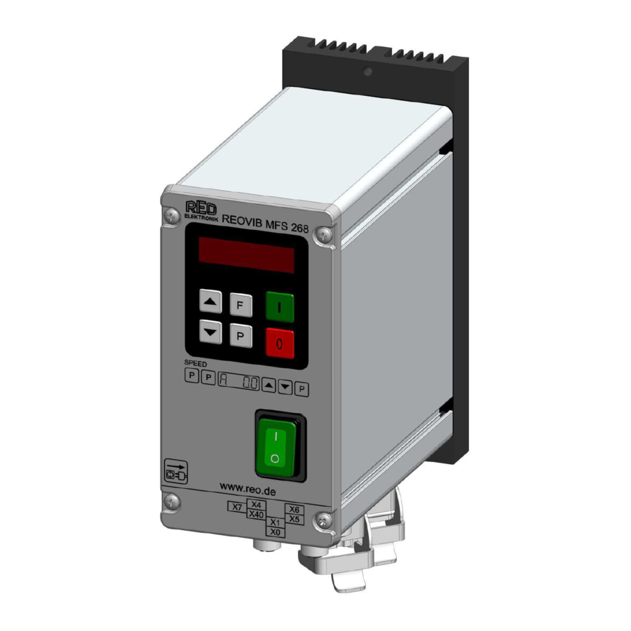
REOVIB MFS 268 UL/CSA Operating Instructions ELEKTRONIK 8.0 Control elements 8.1 Settings The six buttons and a LED display found in the front panel, are used for operating and setting up the unit. All operating methods and adjustable Display parameters can be set up through this panel. -
Page 10: Commissioning
REOVIB MFS 268 UL/CSA Operating Instructions ELEKTRONIK 9.0 Commissioning 9.1 Assembling position Please fasten the devices on a vibration-free underground and take care for sufficient air circulation. 9.2 Preliminary steps • Check that the unit is correct for the local mains supply (rating plate information) and that it is correct- ly rated for the feed system. -
Page 11: Putting The Equipment Into Operation
REOVIB MFS 268 UL/CSA Operating Instructions ELEKTRONIK 9.3 Putting the equipment into operation 1. Establish the vibrating frequency. 2. Establish the power of the feed system (maximum permissible current draw). For a new feeder where settings are unknown: (see also comments below) Without connecting the feeder, select parameter FAC in menu C210 (reset factory settings), press the cursor key to reset (SAFE) and press the P key to leave the menu. -
Page 12: Setting Instructions
REOVIB MFS 268 UL/CSA Operating Instructions ELEKTRONIK 10.0 Setting Instructions 10.1 User adjustment of throughput Code C. 000 Feeder amplitude set point 0...100 % Running mode A further set point code can be found under C002 (for use in coarse/fine operation) Feeder amplitude set point 0...100 %... -
Page 13: Track Control
REOVIB MFS 268 UL/CSA Operating Instructions ELEKTRONIK 10.2.2 Track control Code C. 167, 007 On time delay 0...60 sec. Off time delay 0...60 sec. 0 = No sensor inverting I = Sensor inverting 0 = Sensor time out not active I = Sensor time out active E. -
Page 14: Pulse Feed
REOVIB MFS 268 UL/CSA Operating Instructions ELEKTRONIK 10.2.5 Pulse feed Code C. 004, 064 HOP. = 0 = continuous duty HOP. = I = pulse feed On time delay [sec.] Off time delay [sec.] Invert hopper sensor (not active) Running mode 10.2.6 Regulation mode... -
Page 15: Instructions For Using Regulation Mode
REOVIB MFS 268 UL/CSA Operating Instructions ELEKTRONIK 10.2.6.1 Instructions for using regulation mode • An accelerometer e.g. SW 70 must be fitted to the vibratory feeder in order to run in regulation mode. The accelerometer should have a frequency range corresponding to that of the feeder. - Page 16 REOVIB MFS 268 UL/CSA Operating Instructions ELEKTRONIK In regulation mode the magnitude of the output signal has a direct affect on the maximum ampli- tude of the feeder. On bowl feeders it is advisable to fit the sensor as near as possible to the outside diameter and in this...
-
Page 17: Relationship Between Acceleration And Amplitude
REOVIB MFS 268 UL/CSA Operating Instructions ELEKTRONIK 10.2.6.3 Relationship between acceleration and amplitude The sensor measures the momentary acceleration of the feeder. It generates a sinusoidal output voltage signal. The acceleration gets higher as the frequency increases. The sensor signal is greater for a higher frequency and lower amplitude than for a low frequency with a higher amplitude. -
Page 18: Optimisating Controller In Regulation Mode
REOVIB MFS 268 UL/CSA Operating Instructions ELEKTRONIK 10.2.6.6 Optimisating controller in regulation mode Setting the control range 1. In Menu C. 096 set parameter P (Max Limit) to 50 % 2. Set A (Feeder throughput) to 100% 3. Increase limit P from 50% until the required maximum feeder throughput is achieved The full set point adjustment range of 0…100% can now be used... -
Page 19: Display Actual Current And Frequency
REOVIB MFS 268 UL/CSA Operating Instructions ELEKTRONIK 10.2.7 Display actual current and frequency Code C. 040 Actual current (display only) Actual frequency (display only) Running mode 10.2.8 Save selected parameters Code C. 143 Choose user parameter set Save new parameters Running mode 10.2.9 Recall user or factory settings... -
Page 20: Error Messages / Error Reset
REOVIB MFS 268 UL/CSA Operating Instructions ELEKTRONIK 11.0 Error messages / ERROR reset Errors are indicated by an alternating code and ERROR display Overload limit Output level exceeded e.g. incorrect frequency setting, coil air- gap to wide. Short circuit trip Faulty coil, short circuit or defective cable.. -
Page 21: Connections For Enclosed Construction (Ip 54): 6-8 A Units
REOVIB MFS 268 UL/CSA Operating Instructions ELEKTRONIK 12.0 Connections for enclosed construction (IP 54): 6-8 A Units Internal connections When a potentiometer is connected parameter POT must be set to I in Menu C003. Status- relay 1 2 3 4... -
Page 22: Connections For Enclosed Construction (Ip 54): 12 A Units
REOVIB MFS 268 UL/CSA Operating Instructions ELEKTRONIK 12.1 Connections for enclosed construction (IP 54): 12 A Units Internal connections Status relay Time out +24 V Air valve +24 V +24 V Accelerometer SW... INPUT Set point (external) +10V 0(4)...20mA 0...10V... -
Page 23: Connections For Enclosed Construction (Ip 54): 16 A Units
REOVIB MFS 268 UL/CSA Operating Instructions ELEKTRONIK 12.2 Connections for enclosed construction (IP 54): 16 A Units Internal connections Status relay Time out +24 V Air valve +24 V +24 V Accelerometer SW... INPUT Set point (external) +10V 0(4)...20mA 0...10V... -
Page 24: Connections For Panel Mounting Construction (Ip 20): 3 A, 6 A, 8 A
REOVIB MFS 268 UL/CSA Operating Instructions ELEKTRONIK 13.0 Connections for panel mounting construction (IP 20): 3 A, 6 A, 8 A REOVIB MFS268 Material-Sensor +24V Enable 12...24V, DC Set point 0...10V 0(4)...20mA R=500 OHM black External INPUT orange SW... + 24V... -
Page 25: Connections For Panel Mounting Construction (Ip 20): 16A
REOVIB MFS 268 UL/CSA Operating Instructions ELEKTRONIK 13.1 Connections for panel mounting construction (IP 20): 16A line choke Mains L, N, PE / 115V/230V, 50/60HZ Material sensor +24V Enable 12...24V, DC Set point 0(4)...20mA 0...10V SPEED +10V black orange INPUT Accelerometer SW... -
Page 26: Dimensions For 3 A, 6 A, 8 A Units
REOVIB MFS 268 UL/CSA Operating Instructions ELEKTRONIK 14.0 Dimensions for 3 A, 6 A, 8 A Units Enclosed construction, (IP 54) Ø5,0 REOVIB MFS 268 SPEED www.reo.de Ø5,0 Panel mounting construction, (IP 20) Ø 5,0 Ø 5,0 REOVIB MFS268 REOVIB MFS268 Ø... -
Page 27: Dimensions Of Enclosed Construction (Ip 54) 12 A
REOVIB MFS 268 UL/CSA Operating Instructions ELEKTRONIK 14.1 Dimensions of enclosed construction (IP 54) 12 A Ø5,0 REOVIB MFS 268 SPEED www.reo.de Ø5,0 14.2 Dimensions of enclosed construction (IP 54) 16 A Ø5,0 REOVIB MFS 268 SPEED www.reo.de Ø5,0... -
Page 28: Dimensions Of Panel Mounting Construction (Ip 20) 16 A
REOVIB MFS 268 UL/CSA Operating Instructions ELEKTRONIK 14.3 Dimensions of Panel mounting construction (IP 20) 16 A Ø5,0 SPEED +10V Ø5,0... -
Page 29: A 1.0 Service Appendix
REOVIB MFS 268 UL/CSA Operating Instructions ELEKTRONIK A 1.0 Service appendix ATTENTION ! The settings described in this section relating to the service menu are intended for use by skilled persons because the functions and limits of the feed system can be greatly influenced by their... - Page 30 REOVIB MFS 268 UL/CSA Operating Instructions ELEKTRONIK Frequency adjustment range The control unit is supplied with a maximum frequency range of 5…150Hz. Using an adjustable under and over frequency limits, the user range (parameter F) can be restricted to a maximum ratio of 1:4.
- Page 31 REOVIB MFS 268 UL/CSA Operating Instructions ELEKTRONIK Enable Service Mode The actual service menu is accessed by opening the service mode. 0 = Service mode off I = Service mode on Running mode The normal service menu, containing the output current and frequency limit settings, is accessed by opening the service mode.
-
Page 32: A 2.0 Accessories / Spare Parts
REOVIB MFS 268 UL/CSA Operating Instructions ELEKTRONIK A 2.0 Accessories / Spare Parts Reo Order Type: Accessories / Spare Parts: Number: Manufacturer Order Number: Harting: 09 20 003 2711 + 19 20 003 1440 + mains input coupling 19 00 000 5082 + 09 20 000 9918... - Page 33 REOVIB MFS 268 UL/CSA Operating Instructions ELEKTRONIK...
- Page 34 Headquarters - Germany REO ELEKTRONIK AG Brühler Straße 100 · D-42657 Solingen Tel.: +49 (0)212 8804 0 · Fax: +49 (0)212 8804 188 REO INDUCTIVE COMPONENTS AG Brühler Straße 100 · D-42657 Solingen Tel.: +49 (0)212 8804 0 · Fax: +49 (0)212 8804 188 E-Mail: info@reo.de...
Need help?
Do you have a question about the REOVIB MFS 268 and is the answer not in the manual?
Questions and answers