Table of Contents
Advertisement
Quick Links
TM
Service Manual
®
©2013 Young Chang Co., Ltd. All rights reserved. Kurzweil® is a product line of Young Chang Co., Ltd. Kurzweil®, Young
Chang®, V. A. S. T.®, and SP5-8™ are trademarks of Young Chang Co., Ltd. All other trademarks and copyrights are property
of their respective companies. Product features and specifications are subject to change without notice.
Part Number 910550-001 — May 2013
Advertisement
Chapters
Table of Contents

Related Manuals for Kurzweil sp5-8


Summary of Contents for Kurzweil sp5-8
-
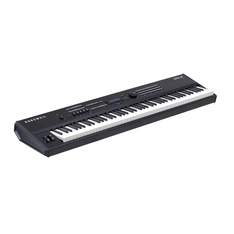
Page 1: Service Manual
©2013 Young Chang Co., Ltd. All rights reserved. Kurzweil® is a product line of Young Chang Co., Ltd. Kurzweil®, Young Chang®, V. A. S. T.®, and SP5-8™ are trademarks of Young Chang Co., Ltd. All other trademarks and copyrights are property of their respective companies. -
Page 2: Radio And Television Interference
CAUTION The lightning flash with the arrowhead symbol, within an equilateral triangle is intended to alert the user to the presence of uninsulated RISK OF ELECTRIC SHOCK "dangerous voltage" within the product's enclosure that may be of sufficient magnitude to constitute a risk of electric shock to persons. DO NOT OPEN CAUTION: TO REDUCE THE RISK OF ELECTRIC SHOCK, The exclamation point within an equilateral triangle is intended... -
Page 3: Important Safety Instructions
IMPORTANT SAFETY INSTRUCTIONS 1) Read these instructions. 2) Keep these instructions. 3) Heed all warnings. 4) Follow all instructions. 5) Do not use this apparatus near water. 6) Clean only with dry cloth. 7) Do not block any of the ventilation openings. Install in accordance with the manufacturer’s instructions. 8) Do not install near any heat sources such as radiators, heat registers, stoves, or other apparatus (including amplifiers) that produce heat. -
Page 4: Kurzweil International Contacts
Kurzweil International Contacts Contact the Kurzweil office listed below to locate your local Kurzweil representative. US Customers: American Music & Sound 22020 Clarendon Street, Suite 305 Woodland Hills, CA 91367 Tel: 800-431-2609 Fax: 818-597-0411 Email: Info@AmericanMusicAndSound.com Customers outside the US: Young Chang Co., LTD. -
Page 5: Table Of Contents
Table of Contents Kurzweil International Contacts ........................iv Chapter 1 Introduction Notes, Cautions, Warnings ........................1-1 Front Panel Features ............................1-2 Shift, Sw, and Zone Buttons and Control Sliders ...................1-2 Mode and Function Buttons ........................1-3 Navigation ..............................1-4 Category Buttons and KB3 LED .......................1-4 Double Press Buttons ..........................1-5... - Page 6 Introduction ................................4-1 Notes, Cautions, Warnings ........................4-1 Cables, Connectors .............................4-1 Required Tools and Materials ........................4-1 Top Enclosure ..............................4-2 Opening the SP5-8 ............................4-2 Removing the Endcaps ..........................4-3 Removing the Top Enclosure ........................4-3 Replacing the Top Enclosure ........................4-4 Replacing the Endcaps ..........................4-5 Closing the SP5-8 ............................4-5 Removing the Engine PCB ........................4-6...
- Page 7 Table of Contents Bottom Enclosure .............................4-13 Removing the Wheels Assembly ......................4-13 Replacing the Wheels Assembly ......................4-14 Removing the Keyboard Assembly .......................4-14 Replacing the Keyboard Assembly ......................4-15 Removing Keys ............................4-15 Replacing Keys ............................4-17 Keyboard Contact PCBs ..........................4-18 Removing the Lo Contact PCB ......................4-18 Replacing the Lo Contact PCB ......................4-18 Removing the Mid Contact PCB .....................4-19 Replacing the Mid Contact PCB......................4-19...
- Page 8 Table of Contents Chapter 7 Schematics Engine PCB —SH7203 CPU, Memory, and Debug UART Header (1 of 5) ..........7-3 Engine PCB—MARA (2 of 5) ...........................7-4 Engine PCB—MARA Clock, Delay Memory, ScanPort, CPLD (3 of 5) .............7-5 Engine PCB—Sound ROM, LCD INTF, Audio Outputs, USB I/F (4 of 5) ..........7-6 Engine PCB—Power Circuitry, Test Headers , Reset (5 of 5) ..............7-7 Front Panel Right PCB—Button, LED (1 of 2) ....................7-8 Front Panel Right PCB (2 of 2) .........................7-9...
-
Page 9: Chapter 1 Introduction
Chapter 1 Introduction This chapter provides the service technician with a layout of the control and rear panel features, as well as a brief explanation of their functions. For complete instructions, consult the SP5-8 Musician’s Guide. Notes, Cautions, Warnings Please pay special attention to all Notes, Cautions, and Warnings symbols used throughout this manual. -
Page 10: Front Panel Features
Introduction Front Panel Features Front Panel Features Zone & Programmable Mode & Buttons Function Category Shift Contrast Buttons Buttons Button Display & LEDs Alpha Wheel Control Sliders Value Buttons Channel/Parameter Buttons Shift, Sw, and Zone Buttons and Control Sliders Master Volume slider—Adjusts the overall volume. Setup Zone buttons—Pressing a Zone button will mute or unmute the zone. -
Page 11: Mode And Function Buttons
Introduction Front Panel Features Control sliders, Shift button and LEDs—These sliders can be assigned to send MIDI continuous controller values. Each slider can control three separate functions giving you access to 15 MIDI continuous controllers. Think of this as three rows of five sliders. Press the Shift button to select a row of sliders. -
Page 12: Navigation
Introduction Front Panel Features Navigation LCD—Twenty character, 2 line liquid crystal display. Previous—Press the Previous button to select the previous or lower value or item. Next—Press the Next button to select the next or higher value or item. Chan / Param Up and Down—Use these buttons to move through the list of available parameters for the current mode. -
Page 13: Double Press Buttons
Double Press Buttons Certain buttons when simultaneously pressed with another button provide secondary functions. These are called double press buttons. A description of each of the SP5-8’s double press buttons begins below. Reset Transposition—Simultaneously press the Transpose – and Transpose + buttons to restore the current program or setup to no transposition. -
Page 14: Rear Panel Features
USB Port—Connect a USB cable to this port to send and receive MIDI, manage user data or to connect to a computer for system updates. MIDI In & Out Port—Use the MIDI In and Out ports to connect the SP5-8 to other MIDI devices to receive and send MIDI data. -
Page 15: Chapter 2 Printed Circuit Boards
Chapter 2 Printed Circuit Boards Function Overview The SP5-8 contains three main printed circuit boards (PCB): the Engine PCB, the Right Front Panel PCB, and the Left Front Panel PCB. To greatly generalize: The Engine PCB contains everything concerning sample playback, audio effects, and the functions of the SP5-8’s operating system. -
Page 16: Cpu
Printed Circuit Boards Function Overview Boot Sequence The SP5-8 uses a modern tiered memory architecture and boots much like a desktop computer. The sequence is essentially: 1. The Right Front Panel PCB, which contains the power supply, produces a signal (PWRUPRST_L) that goes high when the main DC power (+5V) has been stable for approximately 0.5 seconds. -
Page 17: Scanning
• Digital audio formatting circuits The instrument sound samples are stored in Sound ROM (page 4, zone 5D). The standard SP5-8 has 64MB (only U13 installed) of Sound ROM. Other products using the same Engine PCB may have additional Sound ROM installed at U14. -
Page 18: Usb Controller
The CPU has an integrated USB controller that can be either Master or a Slave but not at the same time. Switching circuits (page 4, zone B1) switch between the two functions. In the SP5-8, the actual USB connector is on the Right Front Panel PCB and connects to the Engine PCB by two cables. -
Page 19: Front Panel Pcbs Function Summaries
Panel PCB, Rev. A, schematic circuit drawings (Chapter 7, pages 7-10 and 7-11). In the SP5-8, the main CPU on the Engine PCB also performs scanning of the keyboard, LEDs, and controls. This is done through the ScanPort connector, a simple, Kurzweil standardized, CPU independent interface for scanning. -
Page 20: Right And Left Front Panel Pcbs
Printed Circuit Boards Function Overview Right and Left Front Panel PCBs ScanPort interface to front panel LED indicators (page 1 zone C5–D5) The 25 LEDs on Right Front Panel PCB are in a 6 column 7 row matrix. The column select shift register (U1) drives the next column each time the ScanPort writes new data into the LED row register (U3). -
Page 21: Dc Power Input Jack And Voltage Regulators
Printed Circuit Boards Function Overview DC power input jack and voltage regulators (page 2, zones B4–B6) J7 receives +15V 1.0A power from the external power adapter. L4 and L5 provide RFI filtering and J6 connects to the power switch. U11 is a switching regulator which provides +5V at high efficiency for on-board circuits and the Engine PCB. -
Page 22: Scanport Interface To Pitch And Mod Wheels
Printed Circuit Boards Function Overview ScanPort interface to Pitch and Mod wheels (page 1, zone B4–C5) The pots in the Pitch/Mod wheel assembly turn through only a small part of their rotation range. U20 and associated components amplify the resulting small voltage swing approximately 4X to make a full 0-5V swing for the ScanPort analog multiplexor (described below). -
Page 23: Audio Muting Circuits
Instruments imported into Europe beginning in 2013 must, by law, automatically shut down after a period of inactivity. SP5-8 units exported to Europe implement this by means of a small Automatic Shutdown PCB installed on the rear panel near the DC Power jack. This PCB will interrupt DC power to the Right Front Panel PCB if the unit fails to send any MIDI data for more than approximately four hours. - Page 24 Printed Circuit Boards Automatic Shutdown (ERP Control) PCB 2-10...
-
Page 25: Chapter 3 Diagnostics
• Burn-in Test Entering Diagnostics is one of the available menu options included in the SP5-8 Boot Loader. The following procedure describes entering the boot loader to run the diagnostic tests. The boot loader’s other available menu options and their procedures can be found in Chapter 5 beginning on page 5-2. -
Page 26: Display And Front Panel Buttons
Diagnostic Test Modes Display and Front Panel Buttons Display and Front Panel Buttons In the Diagnostics menu, the display shows the currently selected test, test modes, actions, and test results. Press the Chan / Param Up or Down button to move through the available tests. To select a test, press the Next button. -
Page 27: Description Of Tests
MIDI In jack on the SP5-8‘s rear panel). If a MIDI cable is not connected between SP5-8‘s two MIDI jacks, the display scrolls A failure of this test could be caused by failure of the serial port, other MIDI circuitry, or a problem on the Engine PCB. -
Page 28: Mara Delay Ram
During this test, the volume slider on the SP5-8 is disabled. This is not a test that fails. It is an interactive test for the entire audio chain. However for this test to pass reliably, the MARA Validity, MARA Delay RAM, and MARA Sound ROM tests should pass. -
Page 29: Scanner Diag
Front Panel Buttons—To test a button, press any front panel button. The button number and name shows in the display. Most of the 44 buttons on the SP5-8’s front panel have LEDs. The LED should turn on each time a button is pressed and turn off when the button is released. -
Page 30: Burn-In Test
This test requires a MIDI loop (a MIDI cable that connects the MIDI Out jack to MIDI In jack on the SP5-8‘s rear panel). During Burn-In Loop if a MIDI cable is not connected between SP5-8‘s two MIDI jacks, the test stalls and the display scrolls While running Burn-in Continuous, the test continues but displays a failure. -
Page 31: Chapter 4 Disassembly/Assembly
Introduction This chapter contains the procedures and illustrations for the disassembly and reassembly of the SP5-8. There are three sections: Opening the SP5-8, Top Enclosure, and Bottom Enclosure. Notes, Cautions, Warnings Please pay special attention to all Notes, Cautions, and Warnings as they not only point out specific instructions. -
Page 32: Top Enclosure
Refer to Figure 4-1. Arrows indicate the locations of the enclosure support wall and endcap screws. 1. Position the SP5-8 so that its rear panel portion hangs over the edge of your work surface. This should give you enough room to access the six screws that secure the enclosure support walls. -
Page 33: Removing The Endcaps
Set the endcap safely aside. 4. Slide the SP5-8 back on to your work surface. 5. Repeat Steps 1– 4 for the other endcap. Removing the Top Enclosure Warning: Prepare your work surface. -
Page 34: Replacing The Top Enclosure
Top Enclosure Replacing the Top Enclosure 1. Refer to Figure 4-2. Loosen the two guide screws. You do not need to remove these screws. 2. Remove the remaining six screws that secure the top enclosure to the bottom enclosure. 3. Lift the top enclosure straight up a few inches. Caution: Table 4-1 lists the cables that connect assemblies from the bottom enclosure to the top enclosure. -
Page 35: Replacing The Endcaps
Replacing the Top Enclosure and Replacing the Endcaps. If you have not completed these steps, do so before continuing. 1. Position the SP5-8 so that its rear panel portion hangs over the edge of your work surface. 2. Install the six enclosure support wall screws. -
Page 36: Removing The Engine Pcb
Top Enclosure Removing the Engine PCB Removing the Engine PCB Figure 4-5 Engine PCB 1. Following Steps 2, 3, and 4 disconnect the cables listed in Table 4-2. Ref. Name Cable Type Destination Audio A shielded wire Left Front Panel PCB MIDI/CPU stranded wire Right Front Panel PCB... -
Page 37: Replacing The Engine Pcb
Top Enclosure Replacing the Engine PCB cable wrap MIDI/CPU Power Conn Engine PCB Audio A J7 ScanPort Char LCD plate do not remove Figure 4-6 Engine PCB connector and hardware locations 5. Unwrap the cable wraps at the locations noted in Figure 4-6. 6. -
Page 38: Removing The Right Front Panel Pcb
Top Enclosure Removing the Right Front Panel PCB Removing the Right Front Panel PCB 1. Follow the procedure to remove the top enclosure. Note: Prepare your work surface. Be sure to place the top enclosure on foam or other soft surface to prevent damage or scratches to the rotary and slide potentiometers, switch buttons, the LCD, and front panel. -
Page 39: Replacing The Right Front Panel Pcb
Panel Bridge enclosure support wall Figure 4-7 SP5-8 Right Front Panel PCB hardware locations 9. Remove the Right Front Panel PCB. The LEDs, switches, Spin knob, and other components are now accessible. Note: Each switch button has a shroud that positions and locks the switch in place on the Right Front Panel PCB. -
Page 40: Removing The Lcd
Removing the Left Front Panel PCB The Left Front Panel PCB is mounted on the SP5-8 top enclosure. In addition to the screws securing the Left Front Panel PCB to the inside of the top enclosure, there is hardware on the rear panel portion of the top enclosure (securing the rear panel jacks) and slider knobs on the front panel. -
Page 41: Inside The Top Enclosure
Top Enclosure Removing the Left Front Panel PCB Inside the Top Enclosure 4. Removing the Left Front Panel PCB requires removing the LCD. Follow the procedure on page 4-10 and remove the LCD. 5. Following Steps 6–9, disconnect the cables listed in Table 4-2. Ref. -
Page 42: Replacing The Left Front Panel Pcb
8. Connect the stranded wire cables in the following order: J1, J2, J20. On the Rear Panel 9. Position the SP5-8 top enclosure so that the rear panel jacks and connectors are accessible. 10. Install the nuts and star washers to secure the audio and pedal jacks. -
Page 43: Bottom Enclosure
4-4 to open the SP5-8 and remove the top enclosure. 1. Refer to Figure 4-9. Slide the left front corner of the SP5-8 forward off of your work surface to access the four screws securing the Wheels Assembly to the bottom enclosure. -
Page 44: Replacing The Wheels Assembly
3. Refer to Figure 4-9. Caution: Step 4 instructs you to lift the back edge of the SP5-8 up to access the three screws secure the back edge of the Keyboard Assembly. You should be in position at the front edge of the SP5-8 to provide added support and protection with your body. -
Page 45: Replacing The Keyboard Assembly
Install the six front screws. Slide the SP5-8 back on to your work surface. Caution: Step 3 instructs you to lift the back edge of the SP5-8 up to access the three screws that secure the back edge of the Keyboard Assembly. You should be in position at the front edge of the SP5-8 to provide added support and protection with your body. - Page 46 Bottom Enclosure Removing Keys Clips on the keyboard Hammer location–strikes Hooks through the chassis pivot the front and rear key front of the keyboard contact on key depression chassis Key Spring Location Figure 4-11 Sharp/black key 3. Insert a small pair of needle-nose pliers between the key clips and the chassis pivot. 4.
-
Page 47: Replacing Keys
Bottom Enclosure Replacing Keys To remove a natural key, lift the key up slightly, then forward. The front edge of the key hooks under the keyboard chassis. To remove a sharp key, lift the key up slightly, then forward. The front edge of the key hooks through the keyboard chassis. -
Page 48: Keyboard Contact Pcbs
Keyboard Contact PCBs Keyboard Contact PCBs The SP5-8 Keyboard Assembly has three Keyboard Contact PCBs: Lo (A0 to E3), Mid (F3-C6), and Hi (C#6 to C8). 1. Place the keyboard upside down on a flat soft surface. Be sure that the keys are resting on a soft surface to avoid scratching or other damage. -
Page 49: Removing The Mid Contact Pcb
Bottom Enclosure Keyboard Contact PCBs d. Apply slight pressure to the back end of the Lo Contact PCB. Doing so, lowers the PCB so that it is laying flat on the keyboard chassis. e. Make sure the alignment posts are positioned through the holes provided for them on the Lo Contact PCB. -
Page 50: Removing The Hi Contact Pcb
Bottom Enclosure Keyboard Contact PCBs Caution: If you need to reposition the PCB, be careful you do not dislodge or damage the keyboard contacts. d. Install the ten screws to secure the Mid Contact PCB to the keyboard chassis. While doing so, include the small flat plate that connects the Lo and Mid Contact PCBs. -
Page 51: Removing The Keyboard Contact Strips
Bottom Enclosure Removing the Keyboard Contact Strips Removing the Keyboard Contact Strips 1. Place the keyboard upside down on a flat soft surface. Be sure that the keys are resting on a soft surface to avoid scratching or other damage. 2. - Page 52 4-22...
-
Page 53: Chapter 5 Troubleshooting & Maintenance
Chapter 5 Troubleshooting & Maintenance Introduction Surface-Mount Devices The removal and replacement of surface-mount devices requires training and proper equipment. If you do not have the training or equipment to remove and replace surface- mount devices, contact the Service Department to order a replacement PCB. International service technicians should contact their appropriate Young Chang Distributor. -
Page 54: Boot Loader
Troubleshooting & Maintenance Boot Loader Boot Loader Use the SP5-8 Boot Loader to enter Diagnostics or perform a hard reset to the unit. You can also install operating system updates and objects into Flash memory. Entering the Boot Loader Press and hold the Shift button and apply power to the unit. When appears in the display, release the Shift button. -
Page 55: Software Updates
Note: The Operating System and Object files are combined in one file type (.KUF). 2. Connect a USB cable from a computer to the USB port on the SP5-8 rear panel. 3. When appears in the display, release the Shift button. -
Page 56: Power Problems
Troubleshooting & Maintenance Power Problems Power Problems Dead: LCD, LEDs not lit Before opening the unit, verify the following: 1. The AC outlet is supplying power. 2. The AC cord is good and properly connected to the unit. 3. Check the power switch, DC power jack, and DC power adapter. The adapter rating must be 15VDC, 1.0A minimum, center pin +. -
Page 57: Front Panel Problems
Troubleshooting & Maintenance Front Panel Problems Front Panel Problems LCD not lit, LEDs are lit 1. If there is audio and the keyboard plays, check LCD contrast adjustment located on the rear panel. Turn the pot back and forth to see if there is any change. 2. -
Page 58: Keyboard Problems
Troubleshooting & Maintenance Keyboard Problems Keyboard Problems Dead Keyboard 1. Follow the instructions outlined in Chapter 3 Diagnostics and run the Scanner DIAG tests. If the tests pass, perform a hard reset. 2. Check the flat ribbon cables connecting the Keyboard Bass and Treble Contact PCBs to the Right Front Panel PCB, locations J5 and J3 respectively. -
Page 59: Interconnect Diagram
Troubleshooting & Maintenance Interconnect Diagram Interconnect Diagram Engine Audio A ScanPort Char LCD J31 MIDI/CPU Power Conn Pwr Sw Treble Bass J4 MIDI J1 ScanPort Control Right Front Panel Bridge Panel PCB Control J1 Pressure Panel (White) Bridge Audio from Engine Pressure Left Front opening... - Page 60 Troubleshooting & Maintenance Interconnect Diagram...
- Page 61 Chapter 6 Replacement Parts Printed Circuit Boards and Assemblies Part No. Description 101010643001 Engine PCB 1010302970 Right Front Panel PCB 1010302990 Left Front Panel PCB 1010600770 Power Switch Assembly 101040072001 LCD Assembly 1010900760 Automatic Shutdown (ERP Control) PCB 6990001390 Keyboard Assembly 88 LK40GH+AFT N093LK10L6 LK Key Contact PCB LO N093LKW0M7...
-
Page 62: Miscellaneous
Replacement Parts Right Front Panel PCB Part No. Description Qty. Reference Destination 208010029 Cap Spinknob For SW44 215010069 Switch button bracket For SW13–35, SW41–SW43 6110100570 Spinknob SW44 LED Blue (KB3) 6190100460 D20–D34, D59–D67 620010006 Jack DC power entry 620030002 Jack MIDI J2, J12 620050008 Jack USB... - Page 63 Chapter 7 Schematics Description Page No. Engine PCB —SH7203 CPU, Memory, and Debug UART Header (1 of 5) page 7-3 Engine PCB—MARA (2 of 5) page 7-4 Engine PCB—MARA Clock, Delay Memory, ScanPort, CPLD (3 of 5) page 7-5 Engine PCB—Sound ROM, LCD INTF, Audio Outputs, USB I/F (4 of 5) page 7-6 Engine PCB—Power Circuitry, Test Headers , Reset (5 of 5) page 7-7...
-
Page 65: Engine Pcb -Sh7203 Cpu, Memory, And Debug Uart Header (1 Of 5)
SP5-8 Service Manual Engine PCB —SH7203 CPU, Memory, and Debug UART Header (1 of 5) VCC33 VCC12 CPU_A_[22:0] CPU_A_[22:0] sh.2,3,4,5 PB7_IN PB6_IN CPU_D_[31:0] CPU_IRQ_1_L CPU_D_[31:0] sh.2,3,4,5 CPU_IRQ_0_L 0.1uF 0.1uF 0.1uF 0.1uF 0.1uF 0.1uF 0.1uF 0.1uF 0.1uF 0.1uF 0.1uF 0.1uF SDRAM BYPASS CAPS... -
Page 66: Engine Pcb-Mara (2 Of 5)
SP5-8 Service Manual Engine PCB—MARA (2 of 5) MARA 1 DECOUPLING CAPS VCC33 VCC33 VCC25 VCC25 VCC25 VCC18 VCC18 VCC18 600 OHM @ 100MHz 0.1uF 0.1uF 0.1uF 0.1uF 0.1uF 0.1uF 0.1uF 0.1uF 0.1uF 0.1uF 0.1uF 0.1uF 100uF 22uF 22uF 0.1uF 0.1uF... -
Page 67: Engine Pcb-Mara Clock, Delay Memory, Scanport, Cpld (3 Of 5)
SP5-8 Service Manual Engine PCB—MARA Clock, Delay Memory, ScanPort, CPLD (3 of 5) SCAN PORT INTERFACE VCC33 VCC33 VCC33 VCC33 RN23 RN24 600 OHM @ 100MHz VCC33_ISO_U14 C102 VCC33 600 OHM @ 100MHz C103 0.1uF sh.1,2,4,5 CPU_D_[7:0] 0.1uF RN25 CPU_D_7... -
Page 68: Engine Pcb-Sound Rom, Lcd Intf, Audio Outputs, Usb I/F (4 Of 5)
SP5-8 Service Manual Engine PCB—Sound ROM, LCD INTF, Audio Outputs, USB I/F (4 of 5) VCC33 sh.2 ROM_A_[24:0] R104 TWEET_LEFT_P LINE_LEFT_P DSDL4 LOUT1+ VCC33 VCC33 LINE_LEFT_M DSDR4 LOUT1- R105 TWEET_LEFT_M DSDL3 Line/Phones L+ LINE_RIGHT_P DSDR3 ROUT1+ Line/Phones L - LINE_RIGHT_M... -
Page 69: Engine Pcb-Power Circuitry, Test Headers , Reset (5 Of 5)
SP5-8 Service Manual Engine PCB—Power Circuitry, Test Headers , Reset (5 of 5) C143 VCC33 220uF HEADER3 C145 FBEAD_SMT C146 2.5 Turn Ferrite Bead 22uF 0.1uF HEADER 6 VOUT 1206 PWRUPRST_L /PWRUPRST +12V +12V 600 OHM @ 100MHz AGND LM1086-ADJ... -
Page 70: Front Panel Right Pcb-Button, Led (1 Of 2)
SP5-8 Service Manual Front Panel Right PCB—Button, LED (1 of 2) REVISION RECORD VCC5 ECO NO: APPROVED: DATE: RN7 6.8K VCC5 COL[0:5] Q1 MMBT2907 COL0 VCC33 0.1uF Q2 MMBT2907 74HCT164 COL1 Q3 MMBT2907 100uf COL2 Q4 MMBT2907 COL3 FBEAD_2.5T_SMT 6.8K... -
Page 71: Front Panel Right Pcb (2 Of 2)
SP5-8 Service Manual Front Panel Right PCB (2 of 2) REVISION RECORD VCC5 ECO NO: APPROVED: DATE: MIDI_OUT MIDI_IN FROWN Usage table for U12, R23, R24, R107 Use only one row KeyID R107 LL4148 VCC33 PC910 5.6K VCC33 LL4148 LL4148... -
Page 72: Front Panel Left Pcb (1 Of 2))
SP5-8 Service Manual Front Panel Left PCB (1 of 2)) REVISION RECORD Control Panel Bridge COL5 ECO NO: APPROVED: DATE: COL4 COL3 SPANAIN_P SPANAIN_P COL2 AGND SPANAIN_N SPANAIN_N COL1 AGND COL0 SWR5 SWR5 SWR6 SWR6 NOMINAL LEFT BOARD VARIATION ZONE1... -
Page 73: Front Panel Left Pcb (2 Of 2)
SP5-8 Service Manual Front Panel Left PCB (2 of 2) REVISION RECORD ECO NO: APPROVED: DATE: U14-A R117 +5REF 1.00K TESTPOINT DNS SPANAIN_P +5REF Volume PITCH NJM4580E VCC5 10.0K 1.00% R37 2.2K +5REF +5REF MMBT2907 R118 14.0K +10V +10V 22PF 1000pF 0.1uf... -
Page 74: Automatic Shutdown (Erp Control) Pcb
SP5-8 Service Manual Automatic Shutdown (ERP Control) PCB KURZWEIL ERP CONTROL BOARD (NOTE: This PCB is present only in units exported to Europe.) 7-12... - Page 75 SP5-8 Service Manual Index Index Disassembly instructions Engine PCB 4-6 Keyboard Assembly 4-14 LCD 4-10 Left Front Panel PCB 4-10 Right Front Panel PCB 4-8 Disassembly instructions, Keyboard Keyboard Contact PCBs 4-18, 4-19, 4-20 removing contact strips 4-21 Assembly instructions...
- Page 76 SP5-8 Service Manual Index Keys Troubleshooting diagram Audio 5-4 natural 4-15 Keyboard 5-6 sharp 4-16 Power 5-4 key clips photo 4-16 key spring photo 4-17 removing 4-15 replacing 4-17 Kurzweil International Contacts iv removing 4-10 replacing 4-10 Left Front Panel PCB...
Need help?
Do you have a question about the sp5-8 and is the answer not in the manual?
Questions and answers