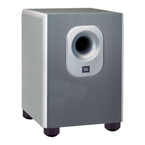
Summary of Contents for JBL SUB200
-
Page 1: Service Manual
Surround Cinema SUB200 Amplifier/Subwoofer SERVICE MANUAL JBL Consumer Products 250 Crossways Park Dr. Woodbury, New York 11797 Rev0 9/2004... -
Page 2: Table Of Contents
SUB200 (SCS200.7sys) Note: The SUB200 is part of the SCS200.7 system Satellite loudspeakers SCS200SAT order JBL part# SCS200SAT-1 Center channel SCS200CEN order JBL part# SCS200/300CEN-1 - CONTENTS - BASIC SPECIFICATIONS……………….….….….….…………….1 DETAILED SPECIFICATIONS ……..…………….……………..2 OPERATION ………….……………………………..…………….4 CONNECTIONS..………………………..………….…….………...5 BASIC TROUBLESHOOTING…..…………….….….…….……...7 TEST SET-UP AND PROCEDURE……..……….…….………….8 EXPLODED VIEW/PARTS LIST…………………………………..9... -
Page 3: Detailed Specifications
SUB200 (SCS200.7sys) JBL SUB200 100W Powered Sub/ Plate Amp LINE VOLTAGE Yes/No Hi/Lo Line Unit Notes US 120VAC/60Hz 108-132 Vrms Normal Operation Normal Operation Asia 100VAC/50Hz 90-110 Vrms EU 230VAC/50-60Hz 207-264 Vrms Normal Operation Normal operation, MOMS required QA Test... - Page 4 SUB200 (SCS200.7sys) QA Test Parameter Specification Unit Limits Conditions Notes Amp connected and AC on, then input ATO Turn-on time Functional signal applied T before muting, after signal is Auto Mute/ Turn-OFF Time minutes Functional removed Auto turn of time (T) must be 10 > T <15 sec.
-
Page 5: Operation
Move the Master Power å switch (marked “Power” to the “•” (On) position to ∫ use the SUB200 subwoofer. If you will be away from home for an extended period of time, or if the subwoofer will not be used, switch the å... - Page 6 SUB200 (SCS200.7sys) DOLBY* DIGITAL OR DTS ® (OR OTHER DIGITAL SURROUND MODE) CONNECTION RECEIVER SUBWOOFER Connect this jack to the LFE 7.1-channel operation as output or subwoofer output appropriate. The front left, LINE on your receiver or amplifier. front right, center and rear...
- Page 7 SUB200 (SCS200.7sys) DOLBY PRO LOGIC (NON-DIGITAL) – SPEAKER LEVEL Use this installation method Right Front Left Front for Dolby Pro Logic applica- Center tions (not Dolby Digital, DTS – – – or other digital processing), where the receiver/processor does not have a subwoofer...
-
Page 8: Connections
SUB200 (SCS200.7sys) TROUBLESHOOTING If there is no sound from any owner’s manual for that electrical outlet, and is å of the speakers: product for further informa- turned on (Power switch tion. If the problem has fol- in the “ • ” position). -
Page 9: Test Set-Up And Procedure
SUB200 (SCS200.7sys) SUB200 Test Set Up and Procedure Equipment needed: Function/signal generator/sweep generator • Integrated Amplifier • Multimeter • Speaker cables • General Unit Function (UUT = Unit Under Test) 1) From the signal generator, connect one line level (RCA) cable to the Subwoofer Line Level Input jacks L/R on the UUT. -
Page 10: Exploded View/Parts List
SUB200 (SCS200.7sys) SUB200 Exploded View SUB200 Cabinet Port Tube Not For Sale 249-ABS-00174 Main Body Rubber Foot (4) 321-ABS-00008 Amplifier Screw (10) Foot Screw (4) 352-AM04020D210 352-HM04030D500 SUB200 Amplifier Rubber Foot Base (4) Not For Sale 321-ABS-00009 Woofer Screw (8) 352-FM04020D605 8"... -
Page 11: Block Diagram
SUB200 (SCS200.7sys) -
Page 12: Pcb Drawings
SUB200 (SCS200.7sys) - Page 13 SUB200 (SCS200.7sys)
- Page 14 SUB200 (SCS200.7sys)
- Page 15 SUB200 (SCS200.7sys)
-
Page 16: Electrical Parts List
SUB200 (SCS200.7sys) SUB200 120v Electrical parts List Part Number Description Reference Designator Main Amp PCB Resistors 110-14472j26 Resistor 4.7K 1/4W ±5% 26mm R147,150 110-14681j26 Resistor 680Ω 1/4W ±5% 26mm R148,151 110-16101j26 Resistor10 0Ω 1/6W ±5%CF 26mm R120 110-16102j26 Resistor 1K 1/6W ±5% CF 26mm... - Page 17 SUB200 (SCS200.7sys) Part Number Description Reference Designator Main Amp PCB 192-021tip35c transistor TIP35C NPN Q107 192-022tip36c transistor TIP36C PNP Q108 192-027c1815gr transistor 2SC1815GR Q101,115 192-201d882Y transistor KSD882Y PNP Q117 192-202b772y transistor KSB772Y PNP Q119 192-991d669a transistor HI-SINCERITY HSD669A NPN Q106...
- Page 18 SUB200 (SCS200.7sys) Part Number Description Reference Designator Input/Preamp PCB 135-3226m50 C225 electolytic 22U 50V ± 20% Semiconductors 192-027c1815gr transistor 2SC1815GR Q201,206,207 197-031n4148 diode 100mA 75V SIGNAL 1N4148 ROHM D201,202,203,204,205,206,207,208,211,212,214 199-15000335 zener diode 3.3V 1/2W 52mm D213 190-06m4558d I.C OPA 4558D DUAL OP-AMP...
- Page 19 SUB200 (SCS200.7sys) Part Number Description Reference Designator MISCELLANEOUS 337-CU-00101 Rubber sheet 350-EM04012D024 Screw 351-AM03008A079 Screw 351-BM03012A088 Screw 351-HM04016A218 Screw 352-AM03008D040 Screw 352-AM03010D065 Screw 354-GM04002 Screw nut 361-FE-00051 IC holder 362-FE-00013 PCB holder...
-
Page 20: Integrated Circuit/Transistor Pinouts
SUB200 (SCS200.7sys) -
Page 21: Schematics
SUB200 (SCS200.7sys) R306... - Page 22 SUB200 (SCS200.7sys) STANDBY DELAY Adjustment Procedure for R138: Use DC voltmeter attached to R140, adjust R138 until the meter reads 510mV (+/-2mV) (for 120v model) 460mV (+/-2mV) (for 230v model) then use "LOCTITE" to fix R138.
-
Page 23: Packaging
SUB200 (SCS200.7sys) SUB200 Packaging Warranty Card Speaker Wire 20 Feet (3) 405-000-00258 166-020F84XX Owner’s Manual Speaker Wire 40 Feet (4) 406-000-00956 166-040F84XX Speaker Wire 15 Feet (2) 166-015F84XX RCA Cable 15 Feet 166-015F011 Floor Stand Adapter (6) 325-ABS-00436 Wall-Mount Bracket (Sats &...


Need help?
Do you have a question about the SUB200 and is the answer not in the manual?
Questions and answers