
Related Manuals for Oridion Capnostream 20p


Summary of Contents for Oridion Capnostream 20p
- Page 1 ® Capnostream Portable Bedside Monitor Capnograph/Pulse Oximeter Operator’s Manual PN: 012194C 0482...
- Page 2 Oridion Medical 1987 Ltd. All information in this manual is believed to be correct. Oridion Medical 1987 Ltd. shall not be liable for errors contained herein with the performance or use of this manual.
-
Page 3: Table Of Contents
Table of Contents Table of Contents List of Figures List of Tables Oridion Medical 1987 Ltd. ("Oridion Medical") - Warranty for Oridion Monitors Safety Information Warnings ........................11 General ............................11 MRI Scanning ..........................12 Monitor Use with Defibrillators ....................12 Alarms ............................ -
Page 4: Microstream Etco 2 Consumables
Storing the Battery ........................24 Disposing of the Battery ......................24 Battery and Power Usage ......................24 Mounting the Monitor..................... 25 Setting up Periodic Maintenance ................... 25 Accessories ........................25 Available Accessories ........................ 25 Monitor Mounting Plate ......................26 Printer Paper ..........................26 Buttons, Indicators and Connections ................ - Page 5 Chapter 5 Capnography with the Capnostream Monitor ® Microstream EtCO Consumables ................53 Basic Principles .......................... 53 ® Microstream EtCO Consumables ................... 54 Connecting a FilterLine ....................54 Data Displayed by the Capnostream Monitor ............54 Adjustable CO Parameters ..................55 Monitoring CO during MRI Scanning ................
- Page 6 Chapter 9 Alarms and Messages Introduction ........................69 Alarm Display ........................ 70 Message Priorities ......................72 Alarm Delay ........................72 Types of Alarms ......................72 High Priority Alarms ........................73 Medium Priority Alarms ......................74 Advisories ........................... 75 Silent Advisories ......................... 75 Parameter Standby Mode .....................
- Page 7 Sample Reports......................101 Sample Case Reports ......................101 Sample Trend Reports ......................102 Chapter 12 Downloading Patient Data Introduction ......................... 103 Data Transfer via the USB Data Port ................103 USB File Naming Convention ....................106 Examples ..........................106 USB Error Messages ....................... 107 Reading Patient Data from Saved Capnostream Files ............
- Page 8 Appendix 1 Institutional Settings Institutional Defaults ....................119 Changing Institutional Defaults ..................119 Resetting to Factory Defaults ..................120 Uploading or Downloading Institutional Defaults ............120 Changing Monitor Settings ..................121 Alarm Limits ..........................121 Alarm Delay ..........................123 Trend Settings .......................... 123 Changing Parameters Order on the Trend Display ..............
- Page 9 Appendix 4 Capnostream Service Password Capnostream Service Password ................. 139 Portable Bedside Capnograph/Pulse Oximeter...
-
Page 10: List Of Figures
List of Figures Figure 1 - Installing the Battery Pack ....................22 Figure 2 - Battery Pack Close-up ......................22 Figure 3 - Menu Bar with Battery Charge Level ................... 23 Figure 4 - Monitor Bottom View ......................25 Figure 5 - Capnostream Front View ..................... 27 Figure 6 - Front Panel Control Buttons .................... -
Page 11: List Of Tables
List of Tables Table 1 - Symbols that Appear on the Monitor ..................16 Table 2 - Capnostream Accessories ....................25 Table 3 - Printer Paper Specifications ....................26 Table 4 - Capnostream Front View ...................... 28 Table 5 - Capnostream Rear View ....................... 29 Table 6 - Capnostream Left View ...................... -
Page 12: Oridion Medical 1987 Ltd. ("Oridion Medical") - Warranty For Oridion Monitors
Furthermore, this limited warranty shall not apply to the use of Products in an application or environment that is not within Oridion specifications or in the event of any act, error, neglect or default of Customer. Oridion at its sole discretion will replace or repair the damaged Products. -
Page 13: Safety Information
Do not touch this field - it is invisible and does not appear in the final document Safety Information Warnings Definitions ® To use the Capnostream monitor (henceforth referred to as Capnostream) correctly and safely, carefully ® read this operator’s manual and the Directions for Use that accompany Microstream etCO consumables ®... -
Page 14: Mri Scanning
Warnings WARNING: If calibration does not take place as instructed in the relevant service manual, the monitor may be out of calibration. A monitor that is out of calibration may provide inaccurate results. Note: Devices connected to the monitor must be medical grade only. Note: The accurate display of the following parameters is required in order to fill the essential performance of the device: Carbon dioxide levels in expired breath (CO... -
Page 15: Electrical
Warnings WARNING: The FilterLine may ignite in the presence of O when directly exposed to laser, ESU devices, or high heat. When performing head and neck procedures involving laser, electrosurgical devices or high heat, use with caution to prevent flammability of the FilterLine or surrounding surgical drapes. -
Page 16: Definitions
Definitions it is possible that high levels of such interference due to close proximity or strength of a source may result in disruption of performance of this device. WARNING: Operating high frequency electrosurgical equipment in the vicinity of the monitor can produce interference in the monitor and cause incorrect measurements. -
Page 17: About This Manual
Chapter 1 Do not touch this field - it is invisible and does not appear in the final document About this Manual Overview Intended Use Specific Indications for Use Who Should Read This Manual Contacting Technical Support Symbols Overview This manual provides directions for setting up and operating the Capnostream monitor. The Capnostream is a portable bedside monitor that continuously monitors a patient’s: •... -
Page 18: Specific Indications For Use
In the United States, federal law restricts this device to sale by or on the order of a physician. Contacting Technical Support For any technical issue involving the Capnostream monitor, please contact Oridion Technical Support, as follows: North America: Tel: 1-888-ORIDION (674-3466), Fax: (781) 453-2722; Outside North America: Tel: + (972) 2-589-9104, Fax: + (972) 2-582-8868;... - Page 19 Symbols Symbol Description Pump Off Temporarily silence alarms Type BF Defibrillator Proof Protection General warning sign Gas inlet Gas outlet Equipotential ground USB flash memory connection port CE Mark For prescription use only Directive on waste electrical and electronic equipment Follow instructions for use Portable Bedside Capnograph/Pulse Oximeter...
-
Page 21: Technology Overview
Chapter 2 Technology Overview Introduction Features Technology Overview Introduction The Capnostream bedside monitor provides accurate, continuous capnography and pulse oximetry monitoring ® for intubated and non-intubated patients from neonate to adult. Using Microstream technology, patented ® FilterLine etCO consumables, and pulse oximetry technology, Capnostream allows for simultaneous "hassle free"... -
Page 22: What Is Pulse Oximetry
Technology Overview Infrared spectroscopy is used to measure the concentration of molecules that absorb infrared light. Because the absorption is proportional to the concentration of the absorbing molecule, the concentration can be determined by comparing its absorption to that of a known standard. ®... -
Page 23: The Capnostream Monitor
Chapter 3 Do not touch this field - it is invisible and does not appear in the final document The Capnostream Monitor Unpacking and Inspection Installing the Battery Pack Mounting the Monitor Setting up Periodic Maintenance Accessories Buttons, Indicators and Connections Front Panel Control Buttons Turning on the Monitor Standard Sections of the Display Screen... -
Page 24: Installing The Battery Pack
Installing the Battery Pack Note: When unpacking the monitor, packaging waste shall be disposed of as according to local regulations for the disposal of packaging waste. Installing the Battery Pack WARNING: The unit should always be operated with the battery installed in order to provide back-up power in the event of a momentary or temporary power outage. -
Page 25: Testing The Battery And Ac Connections
Installing the Battery Pack Ensure that the battery pack is fully charged before using the monitor without AC power. A fully charged battery pack provides 2.5 hours of operation (without printer usage). When the monitor is connected to the AC mains, the battery pack charges automatically. -
Page 26: Storing The Battery
Installing the Battery Pack Storing the Battery The battery pack must be stored in a cold, dry area, not inside the monitor. Its charge decreases over time. To restore the battery pack to full power, recharge the battery before use. The battery should be fully recharged every 3 months at minimum. -
Page 27: Mounting The Monitor
GCX model FLP-002-17C mounting plate which fits onto the GCX model RS-0006-64D Roll Stand Assembly). The VESA mounting plate can be ordered from Oridion; part number is 010713. Please refer to the appropriate Directions for Use for these products. -
Page 28: Monitor Mounting Plate
Replacement paper rolls that meet the specifications can be obtained from Oridion (part number 010516 for a package of 6 rolls), or in North America from www.thermalpaperdirect.com... -
Page 29: Monitor Front View
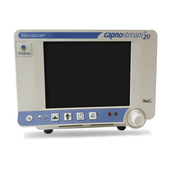
Buttons, Indicators and Connections Monitor Front View The front panel of the monitor contains the display screen, action buttons and the control knob. Figure 5 - Capnostream Front View Table 4 - Capnostream Front View lists the numbered labels. Portable Bedside Capnograph/Pulse Oximeter... -
Page 30: Front Panel Control Buttons
Front Panel Control Buttons Table 4 - Capnostream Front View Label Name Description Label Name Description Monitor power Button switch Temporary Temporarily disables the ON/OFF alarm silence Audio Alarm for two button minutes. AC power Orange light Red alarm Indicator that flashes indicator indicator during High Priority... -
Page 31: Monitor Rear Panel
Front Panel Control Buttons Monitor Rear Panel The rear panel of the monitor contains power and communications connections. Figure 7 - Capnostream Rear View Table 5 - Capnostream Rear View describes the functions of the rear-monitor connections. Table 5 - Capnostream Rear View Label Function Description... -
Page 32: Monitor Left And Right Views
Turning on the Monitor Monitor Left and Right Views The left side of the monitor contains the battery housing and the connection points to the patient interface. Figure 8 - Capnostream Left View Table 6 describes the functions of the features on the left side of the monitor. Table 6 - Capnostream Left View Label Function... -
Page 33: Standard Sections Of The Display Screen
Standard Sections of the Display Screen T O TURN ON THE MONITOR 1. Plug the electrical cord into the mains plug in the rear of the monitor (see Figure 7 - Capnostream Rear View on page 29). Clip the power cord strain relief around the cable and tighten to ensure that the power cord does not accidentally disconnect from the monitor. -
Page 34: Home Screen Standard Display
Standard Sections of the Display Screen The Home screen displays the CO and SpO information along with the IPI value and other information that is standard on most other screens. This section explains the main parts of the screen. The Home screen can display in one of two basic formats: graphical and numeric. The default display is the standard display, described below. - Page 35 Standard Sections of the Display Screen Figure 11 - Typical Home Screen when A/hr and ODI are not Available The Home Screens contains the following sections: • Header Area described on page • Menu Bar described on page • Real Time IPI Data with Trend Graphical Display described on page •...
-
Page 36: Table 7 - Header Section
Standard Sections of the Display Screen Header Area Real Time Numeric Data CO2 Waveform Real Time A/hr and ODI Data Numeric Data SpO2 Waveform Menu Bar Figure 12 - Standard Home Screen without IPI Option Header Area The Header section is always displayed along the top of the screen and contains the information listed in the table below. - Page 37 Standard Sections of the Display Screen Menu Bar The menu bar of available options and functions is located along the bottom of the monitor display screen. At the left hand side is the battery charge level indicator. At the right hand side is the speaker volume control. The menu bar will change depending on which options and functions are available for a specific screen.
-
Page 38: Home Screen Numeric Display
Standard Sections of the Display Screen that the A/hr and O Desat screen should be viewed. The A/hr and O Desat screen is reached with the REPORTS menu button. For more information about the A/hr Visual Alert, see A/hr Visual Alert on page 66. -
Page 39: Terminating Operation Of The Monitor
Terminating Operation of the Monitor When the etCO , FiCO , or RR alarm limit threshold is crossed, the device will alarm: the affected numeric will flash, the numeric will appear with a red or yellow background (depending on whether it is a high priority patient urgent alarm or a caution alarm), and a message will appear in the header area of the screen. -
Page 40: Configuration Changes
Setting Date, Time, Language, and Other Options T O MOVE AROUND THE SCREEN 1. Turn the control knob to the right or left to move to the next area on the screen, which is highlighted by the frame changing to blue. 2. -
Page 41: Screen Timeouts
Screen Timeouts Figure 15 - System Setup Screen Screen Timeouts Screen Timeouts All setup and system screens will timeout after 60 seconds of no activity with the control knob, and revert back to the home screen. Portable Bedside Capnograph/Pulse Oximeter... -
Page 42: Capnostream ® 20 P : Operational Check Sheet
Capnostream®20p: Operational Check Sheet ® Capnostream : Operational Check Sheet To get the Capnostream monitor up and running quickly and smoothly, follow the list of instructions below: 1. Unpack the monitor • Remove the Capnostream monitor and the accessories from the box. •... - Page 43 Capnostream®20p: Operational Check Sheet 10. Open a Patient Case • To record patient data so that it is easy to track and retrieve, opening a patient case is recommended. Opening a patient case is required when recording a Tabular Case Report. •...
-
Page 45: Using The Capnostream Monitor
Chapter 4 Do not touch this field - it is invisible and does not appear in the final document Using the Capnostream Monitor Preparing the Monitor for a Patient Using Patient Cases and Patient ID Numbers Entering Patient Events Changing the Alarm and Pulse Volumes Alarm Delay Use of Scavenging System Turning the Pump Off for Suction or Lavage... -
Page 46: Using Patient Cases And Patient Id Numbers
Using Patient Cases and Patient ID Numbers Pediatric 3-6 yrs: for patients aged three to six years Pediatric 6-12 yrs: for patients aged six to twelve years. Adult: for patients aged 12 years and up The patient type is displayed at the top left hand corner of the screen. Setting the patient type is compulsory. The original default patient type on the monitor is ADULT;... - Page 47 Figure 34 - Trend Memory Message page 90. Oridion strongly suggests that you do so in order to avoid mis-identification of patient data. However, if you intend to continue monitoring the same patient as previously, you may want to retain the trend and case data.
-
Page 48: Entering Patient Events
Entering Patient Events Entering Patient Events When scanning patient history in the monitor, it is often useful to have a record of patient events that could have influenced the recorded readings. The monitor has the ability to record a wide variety of patient events. There are two options: Quick Events and Detailed Events. -
Page 49: Pulse Tone Volume
Changing the Alarm and Pulse Volumes Speaker Volume icon Figure 16 - Menu Bar 2. Click the control knob once to select the alarm volume control. 3. Turn the control knob to raise or lower the volume. The selected alarm volume level will be audible as you turn the knob. -
Page 50: Alarm Delay
Alarm Delay CAUTION: The Audio off option (which will create permanent alarm silence) should be set in the Institutional Defaults only in a situation in which the caregiver is also monitoring the patient by other means, to avoid the chance of missed alarms. Alarm Delay An option for Alarm Delay (for a number of alarms) is available. -
Page 51: Demo Mode
Demo Mode Note: While the pump is off, CO is not monitored and no breath waveform, etCO , FiCO , or respiration rate number values are displayed. SpO and pulse rate monitoring continues. 2. Pump Off mode can be ended by pressing the Pump Off button again. 3. - Page 52 Monitor Screen Menu Reference Chart Figure 20 - Screen Menu Reference Chart when A/hr and ODI are available Portable Bedside Capnograph/Pulse Oximeter...
- Page 53 Monitor Screen Menu Reference Chart Figure 21 - Screen Menu Reference Chart when A/hr and ODI are not available Portable Bedside Capnograph/Pulse Oximeter...
-
Page 55: Capnography With The Capnostream Monitor
Chapter 5 Do not touch this field - it is invisible and does not appear in the final document Capnography with the Capnostream Monitor ® Microstream EtCO2 Consumables Connecting a FilterLine CO2 Data Displayed by the Capnostream Monitor Adjustable CO2 Parameters Monitoring CO2 during MRI Scanning ®... -
Page 56: Microstream Etco2 Consumables
Note: The listed products are also available in versions designed for other patient sizes. This listing describes the main products available. For more information about Oridion FilterLines or additional sizing and packaging options for these products, see http://www.covidien.com/rms/brands/microstream. Connecting a FilterLine Before monitoring a patient with capnography, the appropriate FilterLine must be connected to the monitor and to the patient. -
Page 57: Adjustable Co
Adjustable CO2 Parameters Additionally, the monitor can display CO data in trend form, showing time, date, etCO , RR, alarms, events, and a CASE START marker. For more information about trend display, see Chapter 11 Using Trends page 83. When the EtCO High or Low alarm limits are exceeded, the affected numeric will flash to alert the attending health care professional to the specific parameter that is affected. -
Page 58: Monitoring Co During Mri Scanning
Monitoring CO2 during MRI Scanning 4. The changes in the parameters will remain in effect until the device is turned off. Table 10 - Adjustable CO Parameters Parameter Choices Factory Default BTPS* On/Off FiCO Display On/Off Pump-Off Timeout (minutes) 5, 10, 15 or 30 Waveform Scale (mmHg) 50, 100, 150, Auto Auto... -
Page 59: Pulse Oximetry With The Capnostream Monitor
Chapter 6 Do not touch this field - it is invisible and does not appear in the final document Pulse Oximetry with the Capnostream Monitor Nellcor SpO2 Sensors Connecting an SpO2 Sensor to the Monitor SpO2 Data Displayed by the Capnostream Monitor Adjustable SpO2 Parameters SPO2 Alarm Limit Message Nellcor SpO... -
Page 60: Data Update Period, Data Averaging, And Signal Processing
Nellcor SpO2 Sensors Data Update Period, Data Averaging, and Signal Processing The advanced signal processing of the OxiMax™ algorithm automatically extends the amount of data required for measuring SpO and pulse rate depending on the measurement conditions. The OxiMax™ algorithm automatically extends the dynamic averaging time required beyond seven (7) seconds during degraded or difficult measurement conditions caused by low perfusion, signal artifact, ambient light, electrocautery, other interference, or a combination of these factors, which results in an increase in the dynamic averaging. -
Page 61: Performance Considerations
Nellcor SpO2 Sensors MAX-FAST >40 kg ® ® OxiCliq oxygen transducer 10 to 50 kg (single-use only) >30 kg ® ® Dura-Y multisite oxygen transducer D-YS >1 kg (Nonsterile, reusable) For use with Dura-Y sensor: D-YSE 30 kg Ear clip (Reusable, nonsterile) Pedi-Check™... -
Page 62: Connecting An Spo Sensor To The Monitor
Connecting an SpO2 Sensor to the Monitor • poor peripheral perfusion Clean and remove any substances such as nail polish from the application site. Periodically check to ensure that the sensor remains properly positioned on the patient. Select an appropriate sensor, apply it as directed, and observe all warnings and cautions presented in the directions for use accompanying the sensor. - Page 63 SpO2 Data Displayed by the Capnostream Monitor Waveform Bar (plethysmograph) Interference Indicator Pulse Rate Sat Seconds Figure 24 - SpO Data on the Capnostream Monitor - Standard Screen On the standard home screen with IPI enabled (default standard home screen), the plethysmograph (the SpO waveform) is seen as a green vertical bar on the SpO section of the screen (just to the left of the Sat Seconds value).
-
Page 64: Adjustable Spo 2 Parameters
Adjustable SpO2 Parameters , Sat Seconds and Pulse Rate values Figure 26 - SpO Section of Numeric Home Screen Adjustable SpO Parameters The Capnostream monitor provides the option of adjusting some parameter settings used for SpO measurement to suit your patients, your institution's requirements, or other needs. To change these settings on a temporary basis, until the device is turned off, follow the procedure below. -
Page 65: Integrated Pulmonary Index
Figure 27 - IPI Trend Graph A technical note containing details regarding the IPI algorithm is available from Oridion. Since the index uses data from the monitoring of both CO and SpO , it will only be available when both parameters are available. -
Page 66: Warnings
Warnings monitored during sedation or pain management) may require a lower IPI Low Alert threshold to reflect their impaired respiratory capacity. The IPI is available for all three groups of pediatric patients (1-3 years, 3-6 years, and 6-12 years), and for adult patients. -
Page 67: Apneas Per Hour And The Oxygen Desaturation Index
A/hr and ODI Demo Mode Introduction The Apneas per Hour (A/hr) and Oxygen Desaturation Index (ODI) algorithm is part of the Smart Capnography family of innovative algorithms developed by Oridion. Smart Capnography simplifies the use of CO ® monitoring on Microstream enabled products, to improve patient safety and clinical workflow. -
Page 68: A/Hr Visual Alert
Oxygen Desaturation Index (ODI) A/hr Visual Alert The A/hr Visual Alert, which appears as an asterisk next to the A/hr value, is used to indicate to the caregiver that the apnea count in any one hour period during the last 12 hours exceeded a set number. (The default value which will trigger an A/hr Visual Alert is 10.) The asterisk will appear only when an A/hr Visual Alert is triggered, and it is updated once every 10 minutes. -
Page 69: Smart A/Hr And Odi Home Screen Display
Smart A/hr and ODI Home Screen Display Note: Please note that the patient type is used to calculate the A/hr and ODI. For this reason, it is important to choose the patient type correctly. For the same reason, changing the patient type (from adult to pediatric, for example) will clear the A/hr and ODI data stored for the current patient. -
Page 71: Alarms And Messages
Chapter 9 Do not touch this field - it is invisible and does not appear in the final document Alarms and Messages Introduction Alarm Display Message Priorities Alarm Delay Types of Alarms Parameter Standby Mode Alarm Silence Changing Alarm Limits Testing Alarm Settings Alarms and SatSeconds Alarm Limits - Factory Defaults... -
Page 72: Alarm Display
Alarm Display Alarm Type Indicators Audible Numerics Messages Indicator Light Medium Priority Repeated triple Message area Flashing Yellow beep (some messages also in waveform area – see below) Advisories Single Beep Message area Silent Advisories None Message area Some messages are displayed in the waveform area as well as in the message area; these messages are: Waveform Area Messages: •... - Page 73 Alarm Display This screen enables the health care provider to see at a glance how many alarms have been generated over the last hour by the patient, in order to assess patient status. It is reached by clicking the ALARMS soft button on the menu bar, from the Home screen or the Trend screens.
-
Page 74: Message Priorities
Message Priorities The Alarm Review screen will display alarms for the past hour, if the monitor has been running for an hour or more. If the monitor has been running for less than an hour, the screen will display data from the time the monitor was turned on. -
Page 75: High Priority Alarms
Types of Alarms In addition, medium priority alarms, which alert the clinician to device issues (as opposed to patient issues, which are covered by high priority alarms and caution alarms), are also provided. The following is an example for illustration purposes only, showing how the red high priority patient (urgent) alarm and the yellow caution alarm appear on the monitor. -
Page 76: Medium Priority Alarms
Medium Priority Alarms Table 16 - Medium Priority Alarms Message Description Corrective Action ERROR Failure has occurred which Contact Oridion authorized prohibits the operation of the CO personnel. function. ERROR Failure has occurred which Contact Oridion authorized prohibits the operation of the personnel. -
Page 77: Advisories
Types of Alarms Message Description Corrective Action REMOTE SYSTEM Capnostream is no longer Check connection with remote DISCONNECTED connected to a remote system. system This message will only be present if enabled by the host computer, and may have different wording if so programmed by the host computer. -
Page 78: Parameter Standby Mode
Parameter Standby Mode Message Description USB DEVICE FAILED A USB device connected to the monitor has failed. REPORT TRANSFER COMPLETE Data communication is complete. MONITORING HAS BEEN Displays the hours and minutes the pump has been turned off OFF FOR HH:MM during PUMP OFF mode. - Page 79 Parameter Standby Mode In Standard Mode (when Parameter Standby Mode is not enabled), removing a FilterLine or SpO sensor/extension cable from the device will cause a message to appear on the screen (FILTERLINE DISCONNECTED or SpO SENSOR DISCONNECTED, as relevant) but no alarms will sound. Removing the SpO2 sensor from patient will set off an audible alarm and an on-screen message.
-
Page 80: Alarm Silence
Alarm Silence to the FILTERLINE DISCONNECTED or SPO SENSOR DISCONNECTED or SpO SENSOR NOT ON PATIENT alarms, as relevant, which will continue to appear in the waveform and message areas.) Note: A short press on the Alarm Silence button will still turn off the audible alarms temporarily (for 2 minutes), as previously. -
Page 81: Changing Alarm Limits
Changing Alarm Limits When the alarm silence button is pressed, all audible alarms are silenced for 2 minutes. This includes both alarms that were already sounding and also alarms that may occur during the 2 minute period. The 2-minute alarm silence can be cancelled by a second press of the alarm silence button. Visual alarms are still present. -
Page 82: Testing Alarm Settings
Testing Alarm Settings T HANGE LARM IMITS 1. Open the Alarm Limits screen by selecting the ALARM LIMITS button on the Menu bar at the bottom of the Alarm Review screen. 2. To modify a setting, scroll to the individual limit setting using the control knob. Click the control knob to select that setting, and then turn the control knob to select a new value. -
Page 83: Satseconds Alarm Display
Alarm Limits - Factory Defaults SatSeconds is calculated by multiplying the number of percentage points that the %SpO falls outside of alarm limit by the number of seconds that the %SpO level remains outside that limit. This can be stated as an equation: Points x Seconds = SatSeconds Where:... -
Page 84: Alarm Limits - Factory Defaults
Alarm Limits - Factory Defaults Alarm Limits - Factory Defaults The factory defaults for the Adult and Neonatal alarm limits are given in Table 29 - Factory Default Alarm/Indicator Limits on page 122. Caution Alarms are disabled by default. Portable Bedside Capnograph/Pulse Oximeter... -
Page 85: Using Trends
Chapter 10 Do not touch this field - it is invisible and does not appear in the final document Using Trends Introduction The Trend Display Screens Graphical Trend Display Screen Tabular Trend Display Screen Choosing Trend Parameters Important Notes Regarding Trend Reports Specific Events as seen in Trend Data Using the Graphical Trend Screen for Monitoring Patients Printing the Trend Data... -
Page 86: The Trend Display Screens
The Trend Display Screens The Trend Display Screens Trend data is displayed in two different formats; graphical and tabular. The Graphical Trend screen allows you to view the patient data over a longer time scale (2, 4 or 12 hours at a time) and scroll through the data looking for patterns, specific events or alarms. -
Page 87: Using Scroll And Zoom
Graphical Trend Display Screen historic trend pulse oximetry data: SpO data in pink and pulse rate values in green. The bottom graph shows IPI values in an orange-colored graph. On the left hand side of the screen is the historic patient data at the date and time where the cursor is located. The exact recorded date and time of the cursor location are displayed. - Page 88 Graphical Trend Display Screen Figure 32 - Scroll mode in the Graphical Trend 2. When you scroll to the end of the screen and continue to scroll, the screen will change to add the next or previous 1/2 time period to the display (for example, if you are viewing a 2 hour display, from 4 PM to 6 PM, and you scroll backward to reach 4 PM, the yellow line will return to the middle of the screen and you will see 3 PM to 5 PM instead on the screen).
-
Page 89: Tabular Trend Display Screen
Tabular Trend Display Screen To view more information about the displayed patient, use the control knob to select the TABULAR trend display on the Menu Bar, and see the instructions below in the section Tabular Trend Display Screen page 87. Tabular Trend Display Screen ... -
Page 90: Table 20 - Tabular Display Example
Tabular Trend Display Screen The table below gives a sample of the tabular display at a resolution of 1.5 minutes. Table 20 - Tabular Display Example TIME EtCO EVENTS mmHg 12:23 AM May 23 10 12:24 AM May 23 10 12:26 AM May 23 10 12:27 AM... -
Page 91: Choosing Trend Parameters
Choosing Trend Parameters Choosing Trend Parameters The device displays the following trend parameters: EtCO , RR, SpO , PR, and IPI. The desired order of the parameters can be set by the user using the Trend: Display Configuration screen (see Changing Parameters Order on the Trend Display on page... -
Page 92: Clearing Trend Memory
Clearing Trend Memory Clearing Trend Memory It is recommended to erase trend memory when the monitor is switched to a new patient, in order to avoid mistaking the earlier data for the present patient's data. If you are working with cases, and the current case is ended, the trend memory is automatically cleared. -
Page 93: Event Marking Mode
Configuring Trends EVENT MARKING MODE DETAILED TREND GRAPHICAL DISPLAY [hour] 4 hour TREND INCREMENT DISPLAY [min] 1.5 min NURSE CALL DISABLED HOME SCREEN STANDARD HOME IPI DISPLAY (hour) 1 hour IPI ALARM DISABLED The Trend Data parameters are Event Marking Mode, Trend Graphical Display and Trend Increment Display. The Trend Display settings refer to how the screen will be initially be displayed when you enter the Trend mode. -
Page 95: Reports
Chapter 11 Do not touch this field - it is invisible and does not appear in the final document Reports Apnea and O2 Desaturation Report Printed Report Options Printed Reports Sample Reports When the user clicks on the REPORTS button on the Home screen, the Apnea and O Desat (Desaturation) Report will appear on the screen. - Page 96 Apnea and O2 Desaturation Report • TREND – to graphical trend screen • PRINT – brings user to the standard print screen • ZOOM – changes the time period viewed on the screen to another option. Options are 2, 4, and 12 hours.
- Page 97 Apnea and O2 Desaturation Report Average Apnea Per Hour Apnea Counts and Apnea Sums Desat Count Desat Sum Figure 35 - Apnea and Desat Report Screen Patient Information Explanation Seen on Screen A/hr Average A/hr per hour over entire time period which (Apneas per Hour) appears on the screen Apnea Count...
- Page 98 Printed Report Options Figure 36 - Apnea and Desat Printed Report Portable Bedside Capnograph/Pulse Oximeter...
-
Page 99: Printed Report Options
Printed Report Options Printed Report Options Capnostream can be purchased with a built-in thermal strip printer. The report printing menu in Capnostream is for use with the optional printer. To print a report on an external printer, the recommended procedure is to transfer the data to a computer using a USB flash memory device (see Data Transfer via the USB Data Port on page 103). -
Page 100: Table 23 - Printed Reports - Parameters
Printed Reports Figure 37 - Print Screen 5. Choose data to be printed: Select the PRINT FORMAT option from the Print screen. On the Print Format screen, select the parameters that you want to print on the report. Three columns of data appear in one printed report in the tabular formats and two graphs appear in one printed report in the graphical formats. - Page 101 Printed Reports Report Name Description Fields Included Time Frame of Report between data entries is available Patient Readings: Three of the following the lowest resolution parameters (according to parameters available for trend chosen in the PRINT FORMAT screen, see increment display To print a report on page 97): EtCO (30 seconds).
- Page 102 Printed Reports Report Name Description Fields Included Time Frame of Report Real Time Graphical presentation Patient Readings at start of recording Real-time data from time Continuous CO of levels of etCO , with a period: etCO , FiCO , RR, SpO , PR.
-
Page 103: Sample Reports
Sample Reports Sample Reports Sample Case Reports The following are examples of tabular and graphical case reports as described above. Figure 38 - Sample Case Reports Printout Portable Bedside Capnograph/Pulse Oximeter... -
Page 104: Sample Trend Reports
Sample Reports Sample Trend Reports The following are examples of tabular and graphical trend reports as described above. Figure 39 - Printed Trend Reports Portable Bedside Capnograph/Pulse Oximeter... -
Page 105: Downloading Patient Data
Chapter 12 Do not touch this field - it is invisible and does not appear in the final document Downloading Patient Data Introduction Data Transfer via the USB Data Port Data Transfer via the RS-232 Port Analog Data Output with Capnostream Nurse Call Operation Types of Nurse Call Systems Operation with Hospital Patient Data Systems... - Page 106 Data Transfer via the USB Data Port Report Name Description Fields Included Real Time Continuous Tab delimited (.txt) file with data entries DATE, TIME Waveform every 50 milliseconds. Patient Reading every 50 milliseconds (for creating CO waveform): CO Real Time Continuous Tab delimited (.txt) file, similar to the DATE, TIME Tabular...
-
Page 107: Table 25 - Select Data Output Type
Data Transfer via the USB Data Port 2. When the Flash Memory drive is detected the USB icon will appear in the top right-hand corner of the display beside the alarm symbol. Depending on the type of drive, this may take up to 40 seconds. USB port icon Figure 41 - USB Icon Note:... -
Page 108: Usb File Naming Convention
Data Transfer via the USB Data Port Tabular Trend: 1 hour @30s resolution: 24kB Real time Continuous CO Waveform: 1 hour @50ms resolution: 4.2MB Real time Continuous Tabular: 1 hour @2s resolution: 264kB Full Continuous Transfer: 1 hour @50ms resolution: 12MB Full Binary Continuous Transfer: 1 hour @50ms resolution: 732kB Full Binary Trend Transfer: 1 hour @30s resolution: 5kB USB File Naming Convention... -
Page 109: Usb Error Messages
Nurse Call alarm output also becomes inactive. A Nurse Call cable (3.5 m) can be purchased from Oridion (part number 011149). One end of the Nurse Call Cable attaches to the Capnostream monitor. The cable is supplied un-terminated so it can be built to fit your nurse call system. -
Page 110: Types Of Nurse Call Systems
Types of Nurse Call Systems Types of Nurse Call Systems From an alarm activation / deactivation perspective, Nurse Call Systems can usually be configured in two ways, latching and non-latching. Latching systems: the nurse call light/alarm will remain active until the connected device ceases to alarm and until the nurse cancels the alarm by pressing the nurse call system’s CANCEL ALARM button. -
Page 111: Activating Nurse Call
Types of Nurse Call Systems Nurse Call Connection Figure 43 - Connection Point for Nurse Call Activating Nurse Call The factory default setting for Nurse Call is disabled, and to operate the feature it must be enabled. This can be done using the System Setup screen, however, it will reset to disabled again when the monitor is turned off. -
Page 112: Operation With Hospital Patient Data Systems
IT department representative. All physiologic patient data developed by the Capnostream is sent to the VEGA system to be used by the clinical information system. For more information regarding the Nuvon VEGA system contact an Oridion sales representative or a Nuvon sales representative directly. -
Page 113: Maintenance And Troubleshooting
Chapter 13 Do not touch this field - it is invisible and does not appear in the final document Maintenance and Troubleshooting Introduction Determining Monitor Service Hours CO2 Calibration CO2 Calibration Check Maintenance Replacing the Fuses Replacing the Printer Paper Roll Cleaning Troubleshooting Returning the Monitor... -
Page 114: Co 2 Calibration
CO2 Calibration Figure 44 - Service Screen When the monitor reaches 30,000 hours of use, send it to an authorized service center. Contact your local representative for shipping instructions. Calibration Note: The unit is calibrated when it leaves the factory. The monitor should be calibrated by qualified service personnel after the first 1,200 operating hours of use or 12 months, whichever comes first. -
Page 115: Co 2 Calibration Check
CO2 Calibration Check To display the date of the last calibration, enter the service mode and go to the Calibration Screen. From the Home screen select the SYSTEM button to open the System screen and then select the SERVICE button to open the Service screen. -
Page 116: Maintenance
8. If the calibration check result indicates that the monitor is out of calibration, the message MEASURED CO NOT WITHIN SPECIFICATIONS. CALIBRATION RECOMMENDED is displayed. In this case, the Calibration Procedure must be performed. Refer to the Service Manual or to authorized Oridion Service personnel. -
Page 117: Replacing The Printer Paper Roll
Replacing the Printer Paper Roll Replacing the Printer Paper Roll If the printer runs out of paper, replace it with a roll of thermal printer paper (Oridion part # 010516) or similar paper which meets the specifications outlined in the specifications in Internal Thermal Printer (optional) page 131. -
Page 118: Troubleshooting
Troubleshooting CAUTION: Do not spray or pour any liquid directly on the monitor, accessories or consumables. CAUTION: Do not use caustic or abrasive cleaners, or harsh solvents, including petroleum-based or acetone solutions, to clean the device. ® CAUTION: Microstream etCO consumables are designed for single patient use and are not to be reprocessed. -
Page 119: Spo 2 Sensor
Troubleshooting Problem Cause Action but pump is not working the monitor. and no CO , EtCO Gold ring worn or dirty. Check that the gold ring on the end of the RR readings are FilterLine connector is present and not shown. -
Page 120: Nurse Call
The Service Manual includes information that is required by qualified personnel to service the monitor. See also the Technical Service area in the Capnography section of our website http://www.oridion.com/. If it is necessary to return the monitor for repairs, contact your local representative for shipping instructions. -
Page 121: Appendix 1
Appendix 1 Do not touch this field - it is invisible and does not appear in the final document Institutional Settings Institutional Defaults Changing Institutional Defaults Resetting to Factory Defaults Uploading or Downloading Institutional Defaults Changing Monitor Settings Institutional Defaults Capnostream is shipped from the factory with all changeable settings configured according to the tables in the section Changing Monitor Settings... -
Page 122: Resetting To Factory Defaults
Resetting to Factory Defaults Resetting to Factory Defaults Each section of settings described below allows you to reset to the factory settings for that specific section. You can also do a global reset of all settings in all sections to their factory defaults. To do this, select RESET when you first select the Institutional Defaults screen. -
Page 123: Changing Monitor Settings
Changing Monitor Settings Figure 47 - Software Support Screen Changing Monitor Settings Alarm Limits There are two sets of alarm limits that are stored in the monitor, for Adult/Pediatric and for Infant/Neonatal patient types. (The Adult/Pediatric limits are relevant for adult patients and for all three pediatric patient types.) The factory default settings for Adult and Neonatal alarm limits are given above in Table 29 - Factory Default Alarm/Indicator Limits... -
Page 124: Table 29 - Factory Default Alarm/Indicator Limits
Changing Monitor Settings Figure 48 - Institutional Defaults Alarm Limits Screen The factory default settings for Adult/Pediatric and Infant/Neonatal alarm limits are given below. Table 29 - Factory Default Alarm/Indicator Limits Parameter Adult/Pediatric Adult/Pediatric Infant/Neonatal Infant/Neonatal Range Red Urgent Yellow Caution Red Urgent Yellow Caution Alarm... -
Page 125: Alarm Delay
Changing Monitor Settings Alarm Delay A number of alarms can be delayed by a choice of 10, 15, 20, or 30 seconds, or not at all (Alarm Delay disabled). This option is available for all patient types. The Alarm Delay can be set from the Institutional Defaults screen, which can be reached by SYSTEM>SERVICE>INPUT SERVICE PASSWORD (see Capnostream Service Password on page 139) -
Page 126: Events
Changing Monitor Settings knob, and then scroll with the control knob until you reach IPI in the Parameters Available column. Click with the control knob to place IPI as the first parameters on the trend displays. Click BACK>BACK>BACK>HOME to retain your choices once you are finished changing the trend display. To return to the default display, click FACTORY DEFAULTS on the Institutional Defaults: Trend: Display Configuration screen. - Page 127 Changing Monitor Settings Figure 49 - Institutional Defaults: Monitor The Institutional Defaults that can be set for the monitor are as follows: Parameter Choices Factory Default Date Format dd mmm yy or mmm dd, yy mmm dd, yy Time Format 12 or 24 hour 12 hour Language...
-
Page 128: Co 2 Parameters
Changing Monitor Settings Parameters Institutional Defaults can be set for all CO parameters that are settable in the monitor. To change the parameters, select CO in the Institutional Defaults screen. Parameter Choices Factory Default Units mmHg, kPa, Vol% mmHg BTPS* On/Off FiCO Display... -
Page 129: Appendix 2
Appendix 2 Do not touch this field - it is invisible and does not appear in the final document Specifications Power Supply Battery Controls Display Microstream® Capnography Nellcor Oximax® Pulse Oximetry Alarms Outputs Internal Thermal Printer (optional) General Characteristics Equipment Classification Compliance Power Supply Item... -
Page 130: Display
Display Display Item Value Screen 162mm (6.4in) Color TFT Display Pixel Pitch: 0.204 (H) x 0.204(V) mm (0.008in) Active Display Area: 130.56 (H) x 97.92 (V) mm (5.14in x 3.86in) Resolution 640 x 480 pixels Viewing angle (vertical) 110° Viewing angle (horizontal) 140° Trace Speed 3.0, 6.3, 12.5 and 25 mm/sec Waveform sampling rate... -
Page 131: Nellcor Oximax ® Pulse Oximetry
Nellcor Oximax® Pulse Oximetry ® Nellcor Oximax Pulse Oximetry Item Value Measurement Range 0-100% Accuracy* Adult and Pediatric Modes ± 2 digits range 70% - 100% range 0 - 69% Unspecified Infant/Neonatal Mode ± 3 digits range 70% - 100% range 0 - 69% Unspecified Pulse Rate Range... -
Page 132: Nurse Call
Outputs Assignment Assignment Ground Ground Ch 1 Signal Ground Ground Ch 5 Signal Ch 2 Signal Ground Ground Ch 6 Signal Ch 3 Signal Ground Ground Ch 7 Signal Ch 4 Signal Nurse Call Normally Open/ Normally Closed Relay Rated Carrying current : 2A Max Allowable Current : 2A Max Allowable Voltage : 24V DC Contact Capacity: 2A @ 24V DC. -
Page 133: Usb
Internal Thermal Printer (optional) RS-232 9-pin female D-type connector Pinout Assignment PC_RX PC_TX Isolated Ground USB Type A Host connector (female) For use only with flash memory drives. Pinout Assignment VBUS Data - Data + Ground Internal Thermal Printer (optional) Item Value Type... -
Page 134: General Characteristics
General Characteristics General Characteristics Item Value Unit Dimensions 167mm(h) x 220mm(w) x 192mm(d) (6.6in (h) x 8.7in (w) x 7.6in (d)) Unit Weight 3.6kg (7.94lb) Operating Temperature 0°C to 35°C (32°F to 95°F) Operating Pressure and Altitude Pressure: 430 mmHg to 795 mmHg Altitude: -381m to 3000m (-1,250 feet to 9,843 feet) Operating Humidity 10% to 95% non-condensing... -
Page 135: Table 32 - Guidance And Manufacturer's Declaration - Electromagnetic Emissions
Compliance Table 32 - Guidance and Manufacturer's Declaration - Electromagnetic Emissions Emissions Test Compliance Electromagnetic Environment – Guidance The Capnostream20P uses RF energy only for its internal function. Therefore, its RF emissions are RF emissions EN 55011 Group 1 very low and are not likely to cause any interference in nearby electronic equipment. - Page 136 Compliance Immunity Test IEC 60601 Compliance Electromagnetic Environment – test level level Guidance Conducted 3 Vrms 150 kHz to Portable and mobile RF RF IEC 61000-4-6 80 MHz communications equipment should be used no closer to any part of the Capnostream20P, including cables, than the recommended separation distance calculated from the equation...
-
Page 137: Table 34 - Recommended Separation Distances Between Portable And Mobile Rf Communications Equipment And The Monitor
Compliance Table 34 - Recommended Separation Distances between Portable and Mobile RF Communications Equipment and the Monitor Rated maximum output power Separation distance according to frequency of transmitter W f transmitter in m √ �� √ �� √ �� 150 kHz to 80 MHz 80 MHz to 800 MHz 800 MHz to 2,5 GHz d= 1.2... -
Page 139: Appendix 3
Appendix 3 Do not touch this field - it is invisible and does not appear in the final document Microstream EtCO Consumables Microstream EtCO2 Consumables Microstream EtCO Consumables H Products (for use in humidified environments) are marked with an asterisk (*) in the table below. Microstream Consumables Intubated Consumables FilterLine Set Adult/Pediatric... - Page 140 Microstream EtCO2 Consumables Microstream Consumables Smart CapnoLine Guardian O long (O tubing) 012530 Smart CapnoLine Guardian O long (O tubing) 100 unit 012539 Hook and Loop Strap 012542 Nasal FilterLine Adult (O tubing) 006912 Nasal FilterLine Adult (O tubing) 100 unit 010304 Nasal FilterLine Adult Long (O tubing)
- Page 141 Appendix 4 Do not touch this field - it is invisible and does not appear in the final document Capnostream Service Password Capnostream Service Password Capnostream Service Password This service password is: SERV Portable Bedside Capnograph/Pulse Oximeter...
Need help?
Do you have a question about the Capnostream 20p and is the answer not in the manual?
Questions and answers