Table of Contents
Advertisement
Quick Links
User Guide
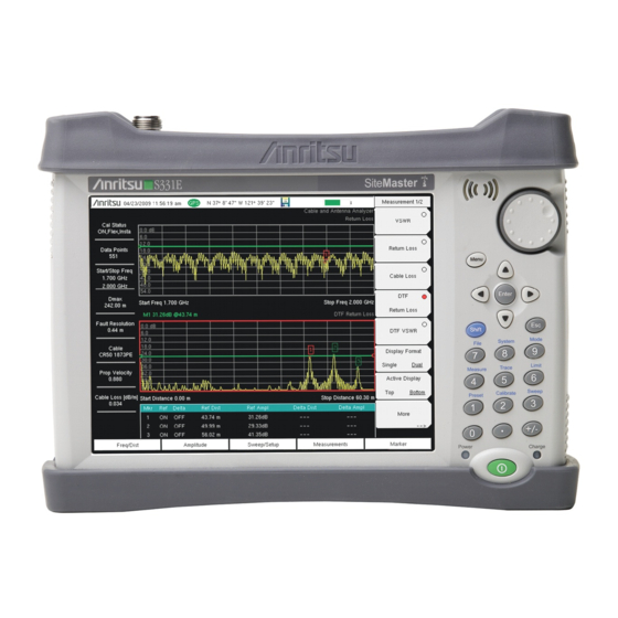
Site Master
Cable and Antenna Analyzer
with Spectrum Analyzer
S331E, 2 MHz to 4 GHz
S332E, 2 MHz to 4 GHz, Spectrum Analyzer, 100 kHz to 4 GHz
S361E, 2 MHz to 6 GHz
S362E, 2 MHz to 6 GHz, Spectrum Analyzer, 100 kHz to 6 GHz
Appendix A provides a list of documentation for the Site Master
features and options. The documentation set is available as PDF
files on the documentation disc and the Anritsu Web site.
Anritsu Company
490 Jarvis Drive
Morgan Hill, CA 95037-2809
USA
Part Number: 10580-00252
Published: December 2015
Copyright 2009, 2015 Anritsu Company
Revision: J
Advertisement
Table of Contents

Related Manuals for Anritsu s331c


Summary of Contents for Anritsu s331c
- Page 1 S362E, 2 MHz to 6 GHz, Spectrum Analyzer, 100 kHz to 6 GHz Appendix A provides a list of documentation for the Site Master features and options. The documentation set is available as PDF files on the documentation disc and the Anritsu Web site. Part Number: 10580-00252 Anritsu Company...
-
Page 3: Table Of Contents
Additional Documentation ........1-1 Contacting Anritsu for Sales and Service ..... . . 1-1 Instrument Description . - Page 4 Table of Contents (Continued) Soft Carrying Case ......... . 2-15 2-10 Tilt Bail Stand .
- Page 5 Table of Contents (Continued) Managing Files ..........4-1 Save Files .
- Page 6 Introduction ..........9-1 Anritsu Tool Box with Line Sweep Tools......9-1 Install the Software .
-
Page 7: Chapter 1-General Information
Download Library tab: • http://www.anritsu.com/en-US/test-measurement/products/s331e • http://www.anritsu.com/en-US/test-measurement/products/s332e • http://www.anritsu.com/en-US/test-measurement/products/s361e • http://www.anritsu.com/en-US/test-measurement/products/s362e Contacting Anritsu for Sales and Service To contact Anritsu, visit the following URL and select the services in your region: http://www.anritsu.com/contact-us. Site Master User Guide PN: 10580-00252 Rev. J... -
Page 8: Instrument Description
1-2 Instrument Description General Information Instrument Description The Site Master S331E/S361E is a handheld cable and antenna analyzer designed to make Return Loss, VSWR, Cable Loss, and Distance-To-Fault (DTF) measurements in the field. The cable and antenna analyzer also includes 1-port phase and smith chart measurements. The 2-port transmission measurement option includes two power levels and access to a built-in 32 volt bias tee (Option 10). -
Page 9: Available Options
PIM Analyzer S331E-0021 S332E-0021 S361E-0021 S362E-0021 2-Port Transmission Measurement Bias-Tee (Requires Option 21 on S331E-0010 S332E-0010 S361E-0010 S362E-0010 S331E and S361E) GPS Receiver (Requires Anritsu GPS S331E-0031 S332E-0031 S361E-0031 S362E-0031 Antenna) S331E-0019 S332E-0019 S361E-0019 S362E-0019 High-Accuracy Power Meter S332E-0029 S362E-0029... -
Page 10: Instrument Care And Preventive Maintenance
1-3 Instrument Care and Preventive Maintenance General Information Instrument Care and Preventive Maintenance Site Master care and preventive maintenance consists of cleaning the unit and inspecting and cleaning the RF connectors on the instrument and all accessories. Clean the Site Master with a soft, lint-free cloth dampened with water or water and a mild cleaning solution. -
Page 11: Esd Caution
General Information 1-3 Instrument Care and Preventive Maintenance ESD Caution The Site Master, like other high performance instruments, is susceptible to electrostatic discharge (ESD) damage. Coaxial cables and antennas often build up a static charge, which (if allowed to discharge by connecting directly to the Site Master without discharging the static charge) may damage the Site Master input circuitry. - Page 12 DC adapter, or outside the Site Master with the optional Dual Battery Charger. Refer to “Battery Symbols” on page 2-11 for a description of battery symbols. Use only Anritsu Company approved batteries, adapters, and chargers with this instrument. Note Anritsu Company recommends removing the battery for long-term storage of the instrument.
-
Page 13: Calibration And Verification
The Cable and Antenna Analyzer mode requires calibration standards for OPEN, SHORT, and LOAD (OSL) or InstaCal module, which are sold separately. Anritsu recommends allowing the instrument to warm up to typical operation Note temperature (approximately 15 minutes) before calibrating. -
Page 14: Recommended Usage In A Secure Environment
1-5 Secure Environment Workplace General Information 1. Turn the instrument on. 2. Press the Shift button then the System (8) button. 3. Press the System Options submenu key. 4. Press the Reset key, then the Master Reset key. 5. A dialog box will be displayed on the screen warning that all settings will be returned to factory default values and all user files will be deleted. -
Page 15: Chapter 2-Instrument Overview
Chapter 2 — Instrument Overview Introduction This chapter provides a brief overview of the Anritsu Site Master. The intent of this chapter is to acquaint the user with the instrument. For detailed measurement information, refer to a specific measurement guide listed in Appendix A, “Measurement... -
Page 16: Front Panel Overview
2-3 Front Panel Overview Instrument Overview The Site Master takes approximately sixty seconds to complete power warm-up and to load the application software. At the completion of this process, the instrument is ready for use. Front Panel Overview The Site Master menu-driven interface is easy to use and requires little training. The Site Master uses a touch screen and keypad for data input. -
Page 17: Front Panel Keys
Instrument Overview 2-3 Front Panel Overview Front Panel Keys Menu Key Press this key to display a grid of shortcut icons for installed measurement modes and user selected menus and setup files. Figure 2-2 shows the Menu key screen with shortcut icons for the installed measurement modes. - Page 18 2-3 Front Panel Overview Instrument Overview Figure 2-3 shows the Menu key screen with shortcut icons for the installed measurement modes and four rows of user-defined shortcuts to menus and setup files. Press and hold down any key for a few seconds to add a shortcut to this screen. To add shortcut setup files (.stp), open the recall menu and hold down on the file name for several seconds.
-
Page 19: Touch Screen Keys
Instrument Overview 2-3 Front Panel Overview Shift Key Pressing the Shift key and then a number key executes the function that is indicated in blue text above the number key. When the Shift key is active, its icon is displayed at the top-right of the measurement display area by the battery charge indicator. -
Page 20: Led Indicators
2-4 Display Overview Instrument Overview LED Indicators Power LED The Power LED is located to the left of the On/Off key. The LED is solid green when the unit is on and slowly blinks when the unit is off but has external power. Charge LED The Charge LED is located to the right of the On/Off key. -
Page 21: Instrument Overview
Instrument Overview 2-4 Display Overview Save Trace GPS Icon Battery Measurement Charge Date/Time GPS Location Title Submenu Touch Screen Keys Frequency Standard Measurement Settings (Touch Screen Shortcuts) Marker Table Main Menu Touch Screen Keys Figure 2-6. Spectrum Analyzer Display (S332E and S362E only) Many of measurement settings are used as touch screen shortcuts. - Page 22 2-4 Display Overview Instrument Overview In addition to the default color display, Site Master offers the following display settings: Black on White for printing and viewing in broad daylight conditions Night Vision optimized for night-time viewing High Contrast for other challenging viewing conditions Default Colors Black on White Night Vision...
-
Page 23: Test Panel Connector Overview
Instrument Overview 2-5 Test Panel Connector Overview Test Panel Connector Overview Test panel connectors for the Site Master S332E are shown in Figure 2-8. RF In External External Reference Trigger USB Mini-B External Power Headset Jack RF Out USB Type A (Option 0411) Figure 2-8. - Page 24 2-5 Test Panel Connector Overview Instrument Overview USB Interface – Type A The Site Master has two Type A USB connectors that accept USB Flash Memory devices for storing measurements, setups data, and screen images. USB Interface – Mini-B The USB 2.0 Mini-B connector can be used to connect the Site Master directly to a PC. The first time the Site Master is connected to a PC, the normal USB device detection by the computer operating system will take place.
-
Page 25: Symbols And Indicators
Instrument Overview 2-6 Symbols and Indicators Symbols and Indicators The following symbols and indicators indicate the instrument status or condition on the display. Calibration Symbols The current calibration status and type is displayed in the upper-left of the screen when in Cable &... -
Page 26: Additional Symbols
The green Charge LED flashes when the battery is charging, and remains on steady when the battery is fully charged. Caution Use only Anritsu-approved batteries, adapters, and chargers with this instrument. When operating from external power without a battery installed, the battery symbol is replaced by a red plug body (Figure 2-11). -
Page 27: Data Entry
Instrument Overview 2-7 Data Entry Data Entry Numeric Values Numeric values are changed using the rotary knob, arrow keys, or the keypad. Pressing one of the main menu keys will display a list of submenus on the right side of the touch screen. When the value on a submenu key is displayed in red, it is ready for changing. -
Page 28: Mode Selector Menu
2-8 Mode Selector Menu Instrument Overview Mode Selector Menu To access the functions under the Mode menu, select the Shift key, then the Mode (9) key. Use the directional arrow keys, the rotary knob, or the touch screen to highlight the selection, and press the Enter key to select. -
Page 29: Soft Carrying Case
Instrument Overview 2-9 Soft Carrying Case Soft Carrying Case The Site Master can be operated while in the soft carrying case. On the back of the case is a large storage pouch for accessories and supplies. To install the instrument into the soft carrying case: 1. -
Page 30: 2-10 Tilt Bail Stand
2-10 Tilt Bail Stand Instrument Overview The soft carrying case includes a detachable shoulder strap, which can be connected to the D-rings of the case. The soft case has panel openings for the fan inlet and exhaust ports. Do not block Caution the air flow through the panels when the unit is operating. -
Page 31: Chapter 3-Quick Start Guide
Chapter 3 — Quick Start Guide Introduction This chapter provides a brief overview of basic measurement setups. For detailed measurement information, refer to a specific measurement guide listed in Appendix A, “Measurement Guides”. This chapter provides quick start measurement information for the following measurement modes: •... -
Page 32: Cable & Antenna Analyzer
3-3 Cable & Antenna Analyzer Quick Start Guide Cable & Antenna Analyzer Set the instrument to Cable & Antenna Analyzer mode as described in the previous section. Select the Measurement Type Press the Measurement main menu key and select the appropriate measurement. Figure 3-2. -
Page 33: Turn On Markers
Quick Start Guide 3-3 Cable & Antenna Analyzer Turn on Markers 1. Press the Marker main menu key. 2. Press the Marker 1 2 3 4 5 6 submenu key and select the marker number 1 button using the touch screen. The underlined number on the Marker submenu key indicates the active marker. -
Page 34: Single Limit Line
3-3 Cable & Antenna Analyzer Quick Start Guide Single Limit Line 1. Press Shift and then Limit (6) to enter the Limit menu. 2. Press the Limit On/Off key to turn on the Limit. 3. Press Single Limit and then use the numeric keypad, the arrow keys, or the rotary knob to change the limit value and then press Enter. -
Page 35: Dtf Setup
Quick Start Guide 3-3 Cable & Antenna Analyzer DTF Setup 1. Press the Measurements main menu key and select DTF Return Loss or DTF VSWR. 2. Press the Freq/Dist main menu key. 3. Press the Units submenu key and select m to display distance in meters or ft to display distance in feet. -
Page 36: Calibrate With Osl Calibration
3-3 Cable & Antenna Analyzer Quick Start Guide Calibrate with OSL Calibration Refer to the Cable & Antenna Measurement Guide listed in Appendix A Note calibration details. 1. Press the Freq/Dist main menu key and enter the appropriate frequency range 2. -
Page 37: Spectrum Analyzer
Quick Start Guide 3-4 Spectrum Analyzer Spectrum Analyzer Set the instrument to Spectrum Analyzer mode as described in Section 3-2 “Measurement Mode Selection” on page 3-1. Set Start and Stop Frequencies 1. Press the Freq main menu key. 2. Press the Start Freq submenu key. 3. -
Page 38: Set The Amplitude
3-4 Spectrum Analyzer Quick Start Guide Set the Amplitude Press the Amplitude main menu key to display the Amplitude menu. Set Amplitude Reference Level and Scale 1. Press the Reference Level submenu key and use the arrow keys, rotary knob, or the keypad to change the reference level. -
Page 39: Single Limit Line
Quick Start Guide 3-4 Spectrum Analyzer Single Limit Line Press the Limit menu key to display the Limit menu. 1. Press the Limit (Upper / Lower) submenu key to select the desired limit line, Upper or Lower. 2. Activate the selected limit line by pressing the On Off submenu key so that On is underlined. -
Page 40: Setting Up Markers
3-4 Spectrum Analyzer Quick Start Guide Setting Up Markers Press the Marker main menu key to display the Marker menu. Selecting, Activating, and Placing a Marker 1. Press the Marker 1 2 3 4 5 6 submenu key and then select the desired marker using the touch screen marker buttons. -
Page 41: Select A Smart Measurement Type
Quick Start Guide 3-4 Spectrum Analyzer Select a Smart Measurement Type In Spectrum Analyzer mode, press Shift then Measure (4) and select a smart measurement using the submenu keys. Figure 3-8. Spectrum Analyzer Measure Menu Site Master User Guide PN: 10580-00252 Rev. J 3-11... -
Page 42: Saving Measurements
Saving files in .VNA or .SPA is recommended as it enables users to edit, view, and analyze traces with Master Software Tools (MST). Anritsu recommends saving files to the internal memory and then transferring the files to an external USB memory device if needed. Refer to Chapter 4, “Copying... -
Page 43: Useful Mst Utilities
Quick Start Guide 3-6 Useful MST Utilities Useful MST Utilities Converting Files to .DAT File Format 1. Establish a connection with MST. 2. Download measurements: a. Go to Sync | Download all measurements. b. Select the folder on the computer or select Local, and then set the location. c. -
Page 44: Group Edit
3-6 Useful MST Utilities Quick Start Guide Group Edit The Group Edit feature allows markers and limit lines to be copied from one trace to all of the traces in a folder. In addition, the title and subtitle can be quickly renamed for all of the traces in a folder. -
Page 45: Print All To Pdf
Quick Start Guide 3-6 Useful MST Utilities Print All to PDF If Adobe Acrobat is installed on the computer with MST, traces can be converted to PDF using Print All and selecting Print to PDF. This creates a compact and portable PDF report of all of the traces in a folder with just one click. - Page 46 3-6 Useful MST Utilities Quick Start Guide 3-16 PN: 10580-00252 Rev. J Site Master User Guide...
-
Page 47: Chapter 4-File Management
Chapter 4 — File Management Introduction This chapter will review the file management features of the Site Master and detail the File menu. The submenus under this menu allow the user to save, recall, copy, and delete files in internal memory or an external USB flash drive. Managing Files Press the Shift key then the File (7) key on the numeric keypad to list the File menu. -
Page 48: Save Dialog Box
4-2 Managing Files File Management Save a Measurement Screen as JPEG Press the Save submenu key, type a name for the JPEG file, confirm that the file type is Jpeg, and press Enter to save. Save Dialog Box The save dialog box (Figure 4-1) is used to store files on the internal memory or an external flash drive. - Page 49 File Management 4-2 Managing Files Often carriers require file names to be reported in special conventions including site number, sector information, color coding, measurement type, termination device, and frequency information. Setup the buttons in this matrix to quickly enter the required file name. 1.
-
Page 50: Recall Files
4-2 Managing Files File Management Recall Files The recall menu enables you to view all the Measurement and Setup files in the internal memory and external USB flash drive. You can sort the recall menu by name, date, or type. You can also select to view only measurement files or setup files by pressing File Type on the Recall dialog box and selecting the file type you want to view. -
Page 51: Copying Files
File Management 4-2 Managing Files Copying Files The steps below detail copying a file from internal memory to an external flash drive. Select the files to copy in the top window and the location for the files to be copied to in the bottom window (Figure 4-4). -
Page 52: Deleting Files
4-2 Managing Files File Management Deleting Files Delete a Selected File or Files Press the Delete submenu key. Highlight the file to be deleted with the touchscreen or the Up/Down arrow keys. Press the Select or De-Select key. The file will be outlined in blue when selected. -
Page 53: File Menu Overview
File Management 4-3 File Menu Overview File Menu Overview Open this menu by pressing the Shift key, then the File (7) key. File Save Measurement As FileName.vna Save Save Measurement Measurement.dat Save Vary by Measurement Measurement.vna Spectrum Save Mode Analyzer Save On... -
Page 54: File Menu
4-4 File Menu File Management File Menu Key Sequence: File Save Measurement As: This key will save the current setup with a user File defined file name. The default file name is changed using the Save submenu. To change the default file name, type in a new file with the touch Save Measurement As screen keyboard and press Enter. -
Page 55: Save Menu
File Management 4-4 File Menu Save Menu Key Sequence: File > Save The top keys in the Save menu will display the available save options based Save on the current measurement mode. Options include: Setup: Setup files contain basic instrument information, Setup measurement mode setup details, measurement marker data, and limit data. -
Page 56: Save Location Menu
4-4 File Menu File Management Save Location Menu Key Sequence: File > Save > Change Save Location This menu and dialog box is used to create folders and select where the Save Location Site Master will save the current file. Select folders or drives with the Up/Down keys, the rotary knob or the touch screen. -
Page 57: Save On Event Menu
File Management 4-4 File Menu Save On Event Menu Key Sequence: File > Save On Event In Spectrum Analyzer mode, this menu is used to auto save measurements Save On... to internal memory after: ...Crossing Limit ...Crossing Limit: Toggling this submenu key to On will save the measurement to internal memory when the measurement has crossed a defined limit line created with the Limit menu. -
Page 58: Recall Menu
4-4 File Menu File Management Recall Menu Key Sequence: File > Recall This menu and dialog box is used to create folders and select where the Recall Site Master will save the current file. Select folders or drives with the Up/Down keys, the rotary knob or the touch screen. -
Page 59: Copy Menu
File Management 4-4 File Menu Copy Menu Key Sequence: File > Copy This menu and dialog box is used to copy folders and files. Select folders or Copy files with the Up/Down keys, the rotary knob or the touch screen. Figure 4-4 on page 4-5 shows the Copy dialog box with two Jpeg images and one... -
Page 60: Delete Menu
4-4 File Menu File Management Delete Menu Key Sequence: File > Delete This menu and dialog box is used to delete folders and files. Select folders Delete or files with the Up/Down keys, the rotary knob or the touch screen. Sort By Sort By: Press this submenu key to sort files and folders by name, by the type of file, or by the date that the file or folder was saved. -
Page 61: Chapter 5-System Operations
Chapter 5 — System Operations Introduction This chapter will review the Site Master system operations. • “System Menu Overview” on page 5-2 • “System Menu” on page 5-3 • “Preset Menu” on page 5-8 • “Self Test” on page 5-8 •... -
Page 62: System Menu Overview
5-2 System Menu Overview System Operations System Menu Overview To access the functions under the System menu, select the Shift key, then the System (8) key. System System Options Display Settings Date Status Brightness & Time Self Ethernet GPS Info Default Colors Test Config... -
Page 63: System Menu
System Operations 5-3 System Menu System Menu Key Sequence: Shift, System (8) Status: Pressing this submenu key displays the current system status, System including the operating system and firmware versions, temperatures and other details such as current battery information. Press Esc or Enter to return to normal operation. -
Page 64: System Options Menu
5-3 System Menu System Operations System Options Menu Key Sequence: Shift, System (8) > System Options Date and Time: This key brings up a dialog box for setting the current date System Options and time. Use the submenu keys or the Left/Right arrow keys to select the field to be modified. -
Page 65: System Options 2/2 Menu
System Operations 5-3 System Menu System Options 2/2 Menu Key Sequence: Shift, System (8) > System Options > More Center Freq Share: Select All Modes to have the current center frequency System Options 2/2 setting carried over when changing measurement modes. This feature is not applicable to measurements which do not have a center frequency setting or Share CF &... -
Page 66: Display Settings Menu
5-3 System Menu System Operations Display Settings Menu Key Sequence: Shift, System (8) > System Options > Display Brightness: The brightness of the display can be adjusted to optimize Display Settings viewing under a wide variety of lighting conditions. Use the keypad, the Up/Down arrow keys or the rotary knob to select a brightness level from 1 to Brightness 9, with 9 being the brightest. -
Page 67: Reset Menu
System Operations 5-3 System Menu Reset Menu Key Sequence: Shift, System (8) > System Options > Reset Factory Defaults: Restores the instrument to the factory default values, Reset including Ethernet (Option 411), language, volume, brightness setting, and user created shortcut icons on the Menu screen. Press the Enter key to Factory initiate the reset, and power-cycle the instrument. -
Page 68: Preset Menu
If the Site Master is within the specified operating range with a charged battery and the self test fails, contact your Anritsu Service Center at http://www.anritsu.com/contact-us. To start a self test when the system is already powered up: 1. -
Page 69: Updating The Site Master Firmware
Updating the Site Master Firmware The Site Master is updated using a USB memory stick. Updated product information can be found on the Anritsu website: http://www.anritsu.com/en-US/test-measurement/rf-microwave/cable-and-antenna-analyzers Search for the product model number. The firmware updates are on the product page under the Library tab in the “Drivers, Software Downloads”... - Page 70 5-6 Updating the Site Master Firmware System Operations 5-10 PN: 10580-00252 Rev. J Site Master User Guide...
-
Page 71: Chapter 6-Gps (Option 31)
50 ppb (parts per billion). In order to acquire data from the GPS satellites, the user must have line-of-sight to the satellites or the antenna must be placed outside without any obstructions. An Anritsu GPS antenna is required. The Site Master Technical Data Sheet provides a list of options and the Note measurements that require GPS (Option 31). - Page 72 6-3 Activating the GPS Feature GPS (Option 31) 4. When the GPS receiver has tracked at least three satellites, the GPS icon will change to GREEN. Latitude and Longitude information is displayed in the white bar on top of the display.
-
Page 73: Saving And Recalling Traces With Gps Information
GPS (Option 31) 6-4 Saving and Recalling Traces with GPS Information Saving and Recalling Traces with GPS Information Saving Traces with GPS Information The GPS coordinates of a location can be saved along with a measurement trace. Refer to the “Save Menu”... -
Page 74: Gps Menu
Short/Open: A short or open exists between the antenna and the connection. If this message is displayed, then remove and replace the GPS antenna. If the message persists, then try another Anritsu GPS antenna (part number 2000–1528-R). If the message persists, then contact your nearest Anritsu Service Center. -
Page 75: Chapter 7-Ethernet Connectivity (Option 411)
Ethernet Connectivity. It also describes the RJ-45 connector, DHCP, and connection tests for the Site Master. Ethernet Connection Network Connection DHCP is the default Ethernet type. If the Anritsu handheld has been set to Manual, Note change to DHCP from the System main menu (Shift+8) > System Options > Ethernet. - Page 76 Gateway: 10.0.0.1 Subnet: 255.255.255.0 d. Close all the open windows and restart the computer and the Anritsu handheld. 5. Open Master Software Tools, press the Network tab then the Query Network for Instruments button. Double-click on the instrument to complete the connection. The instrument model and IP address (10.0.0.2) along with a green connection icon will be...
-
Page 77: Ethernet Configuration On The Site Master
Ethernet Connectivity (Option 411) 7-3 Ethernet Configuration on the Site Master Ethernet Configuration on the Site Master LAN Connection The RJ-45 connector is used to connect the Site Master to a local area network. Integrated into this connector are two LEDs. The amber LED shows the status of the Ethernet Link: Link Up (On) or Link Down (Off). - Page 78 7-3 Ethernet Configuration on the Site Master Ethernet Connectivity (Option 411) To display the IP address with the instrument on, press the Shift key, then the System (8) key, then the soft key and the soft key. The IP address will be System Options Ethernet Config displayed as shown in...
-
Page 79: Ethernet Config
Ethernet Connectivity (Option 411) 7-3 Ethernet Configuration on the Site Master Ethernet Config Press this submenu key to display the Ethernet submenu and to open the Ethernet Editor dialog box in order to set the IP address of the instrument. Figure 7-2. -
Page 80: Ethernet Menu
7-3 Ethernet Configuration on the Site Master Ethernet Connectivity (Option 411) Ethernet Menu Key Sequence: Shift, System (8) > System Options > Ethernet Config Type Ethernet Manual DHCP: Press this submenu key to select whether the address will be entered manually, or will be supplied automatically by a network DHCP Type server. -
Page 81: Dhcp
Ethernet Connectivity (Option 411) 7-4 DHCP DHCP DHCP stands for Dynamic Host Configuration Protocol. It is a protocol that allows a server to dynamically assign IP addresses to devices that are connected to the network. Most networks include a DHCP server to manage IP addresses. When a DHCP server is available on the network, DHCP is the preferred IP address assignment mode. -
Page 82: Example 1
Windows 2000 IP Configuration Ethernet adapter Local Area Connection: Connection-specific DNS Suffix. : us.anritsu.com IP Address... . : 172.26.202.172 Subnet Mask ... : 255.255.252.0 Default Gateway . -
Page 83: Ping Tool
Ethernet Connectivity (Option 411) 7-6 Ping Tool Ping Tool Another tool that can find out if a selected IP address is already on the network is ping. Ping is a harmless way to determine if an address is found on the network, and (if it is found) to receive a reply. - Page 84 7-10 PN: 10580-00252 Rev. J Site Master User Guide...
-
Page 85: Chapter 8-Bias Tee (Option 10)
Chapter 8 — Bias Tee (Option 10) Overview Option 10 provides a bias tee that is installed inside the instrument. The bias arm is connected to a 12 VDC to 32 VDC power source that can be turned on as needed to place the voltage on the center conductor of the instrument’s RF In port. - Page 86 Bias Tee (Option 10) PN: 10580-00252 Rev. J Site Master User Guide...
-
Page 87: Chapter 9-Anritsu Tool Box And Line Sweep Tools
Start and navigate through the Programs folder to the Anritsu folder. Then click on the Anritsu Tool Box shortcut to open the Anritsu Tool Box. Once the Tool Box is open, move the mouse pointer over any of the application icons to view a short description of the application. -
Page 88: Install The Software
Anritsu Map Master software. If this software had already been installed on your computer, the Tool Box will link to it. If not, clicking on the icons will bring you to the Anritsu web site, where you will be able to download the software free of charge. -
Page 89: Why Use Line Sweep Tools
Cable traces, Antenna traces, and Passive Intermodulation (PIM) traces every day. Line Sweep Tools will: • Collect sweeps from Anritsu PIM and Line Sweep gear. • Help verify that those sweeps are done properly and that the Cable, Antenna and PIM sweeps meet specifications. -
Page 90: Using Line Sweep Tools
Figure 9-4. Line Sweep Tools Window Line Sweep Tools can open DAT files from HHST; or VNA/DAT files from Anritsu’s E-series instruments. It also can open PIM files. Either way, the file once opened, can be inspected and modified in many different ways. Line Sweep Tools saves files as a new type of DAT file, and can export traces as VNA, text, JPG, BMP, or PNG. -
Page 91: Marker Presets
Anritsu Tool Box and Line Sweep Tools 9-6 Using Line Sweep Tools Marker Presets The fastest way to manage markers on multiple traces is to use the preset function. The marker and limit line preset toolbar allows users to quickly set all markers and the limit line... -
Page 92: Report Generator
9-6 Using Line Sweep Tools Anritsu Tool Box and Line Sweep Tools To use the renaming grid: 1. Click on the left icon of the Renaming toolbar. 2. Select the filename, title, or subtitle box. Right-clicking on a box will allow you to change the text on the button. - Page 93 Anritsu Tool Box and Line Sweep Tools 9-6 Using Line Sweep Tools Once the report generator is setup, File > Generate Report, will create the PDF. The report will include all traces that were open at the time the report was made (Figure 9-9).
- Page 94 9-6 Using Line Sweep Tools Anritsu Tool Box and Line Sweep Tools PN: 10580-00252 Rev. J Site Master User Guide...
-
Page 95: Chapter 10-Master Software Tools
MST Manual. 10-2 MST Overview Anritsu Master Software Tools is a Windows 2000 and later compatible program for transferring and editing saved measurements, markers, and limit lines to a PC. Master Software Tools will not function on earlier versions of the Microsoft Windows operating system. -
Page 96: 10-4 Installing Mst
10-4 Installing MST Master Software Tools 10-4 Installing MST MST is provided on the CD-ROM included with the instrument. Insert the CD-ROM into a PC to run the installer. Follow the onscreen instruction. 10-5 Connecting to the Instrument Use the USB cable supplied with the test instrument to make the connection. 1. -
Page 97: Appendix A-Measurement Guides
Introduction This appendix provides a list of supplemental documentation for Site Master features and options. These measurement guides are available on the documentation disc and the Anritsu website. Table A-1. Analyzers and Analyzer Options Related Document Site Master Feature (Required Option) - Page 98 Measurement Guides PN: 10580-00252 Rev. J Site Master User Guide...
- Page 99 ....2-9 contacting Anritsu ....1-1 internal memory .
- Page 100 ....5-9 website, contacting Anritsu ..1-1 Index-2 PN: 10580-00252 Rev. J...
- Page 102 Anritsu Company 490 Jarvis Drive Anritsu utilizes recycled paper and environmentally conscious inks and toner. Morgan Hill, CA 95037-2809 http://www.anritsu.com...
Need help?
Do you have a question about the s331c and is the answer not in the manual?
Questions and answers