
Summary of Contents for CASMED fore-sight elite
-
Page 1: User Manual
The con dence of knowing ™ User Manual This User Manual describes the features and operations of the FORE-SIGHT ELITE Tissue Oximeter: Software Version 3.0 or above. PN 21-22-3000 Rev 07... -
Page 2: Revision History
CAS reserves the right to make changes to this manual and improvements to the product it describes at any time without notice or obligation. Trademarks CASMED, the CASMED logo, and FORE-SIGHT ELITE are registered trademarks and The confidence of knowing is a trademark of CAS Medical Systems, Inc. - Page 3 Manufacturers Declaration of Conformity — Electronic Emissions and Immunity The FORE-SIGHT ELITE Oximeter is intended for use in the electromagnetic environment specified below. The customer or the user of the Oximeter should assure it is used in such an environment.
- Page 4 Guidance and Manufacturer’s Declaration – Electromagnetic Immunity The FORE-SIGHT ELITE Oximeter is intended for use in the electromagnetic environment specified below. The customer or the user of the Oximeter should insure that it is used in such an environment. Immunity Test...
- Page 5 CE Marking Information Compliance The FORE-SIGHT ELITE Oximeter bears the CE mark CE-0086 indicating conformity with the provisions of the Council Directive 93/42/EEC concerning medical devices and fulfills the essential requirements of Annex I of this directive. Exceptions None PN 21-22-3000 Rev 07...
- Page 6 Document Conventions Warning: Directions that warn of conditions that put the patient or caregiver at risk Caution: Directions that help to avoid Oximeter damage or data loss Note: Directions that make it easier to use the Oximeter, which may not be readily apparent CAS Medical Systems, Inc.
-
Page 7: Table Of Contents
ontents Preface xiii Purpose � � � � � � � � � � � � � � � � � � � � � � � � � � � � � � � � � � � � � � � � � � � � � � � � � � � � � � � � � � xiii Intended Audience �... - Page 8 Contents Testing the Oximeter Alarms � � � � � � � � � � � � � � � � � � � � � � � � � � � � � � � � � � � � � � � 15 Disconnecting the Preamp Cables �...
- Page 9 FORE-SIGHT ELITE User Manual Placing Event Markers � � � � � � � � � � � � � � � � � � � � � � � � � � � � � � � � � � � � � � � � � � � � 46 Navigating the Event Area �...
- Page 10 Contents Menu Reference Alarms and Messages Event Index Symbol Reference Specifications Parts Warranty Policy Index CAS Medical Systems, Inc.
- Page 11 igures Figure 1: Patient Environment � � � � � � � � � � � � � � � � � � � � � � � � � � � � � � � � � � � � � � � � � � xvi Figure 2: Oximeter —...
- Page 12 ables Table 1: On-Screen Help Options � � � � � � � � � � � � � � � � � � � � � � � � � � � � � � � � � � � � � � � � 6 Table 2: Battery Status Indicators �...
-
Page 13: Preface
Preface Purpose This User Manual describes the features and operation of the FORE-SIGHT ELITE Absolute Tissue Oximeter. It is an integral part of the product and contains the instructions necessary to operate the Oximeter safely and in accordance with its functions and intended use to ensure proper performance, correct operation, and patient and operator safety. -
Page 14: Safety
• When used with large Sensors, the FORE-SIGHT ELITE Oximeter is indicated for use on adults and transitional adolescents ≥ 40 kg (88.2 lbs). - Page 15 FORE-SIGHT ELITE User Manual Measurement Accuracy Cerebral Accuracy Accuracy (Bias ± Precision) not determined outside the following ranges: Large Sensors: 45% to 95%: -0.14 ± 3.05% at 1 SD Medium Sensors: 48% to 92%: 0.05 ± 5.06% at 1 SD Small Sensors: 50% to 90%: -0.01 ±...
-
Page 16: Figure 1: Patient Environment
Preface: Safety Oximeter Classifications Electrical Insulation The Oximeter (with integrated AC power supply) is a Class I device. IEC 60601-1 Warning: The Oximeter is not “Category AP or APG Equipment.” There is a risk of an explosion hazard if a damaged Oximeter or accessory is used in the presence of a flammable anesthetic mixture with air or with oxygen or nitrous oxide. -
Page 17: Parts And Warranty
(minimum 1 hour) and checked by a CASMED-authorized service technician before it is used again. Parts and Warranty CAS Medical Systems, Inc., (CASMED) is responsible for the effects on safety, reliability, and performance of the product only if: • Assembly, operations, extensions, readjustments, modifications, or repairs are carried out by persons authorized by CASMED. - Page 18 Preface: Parts and Warranty Waste Electrical and Electronics Equipment (WEEE) To facilitate the sound treatment of WEEE, information will be made available for current CASMED products upon request. EU distributors and treatment facility personnel may contact techsrv@casmed.com to obtain relevant information.
-
Page 19: Introduction
Sensor on the patient’s forehead. Reflected light is captured by detectors positioned on the Sensor for optimal signal collection. After analyzing the reflected light, the FORE-SIGHT ELITE displays the cerebral tissue oxygen saturation level on the Oximeter as an absolute number and provides a graphical representation of historical values. -
Page 20: About The Oximeter Hardware
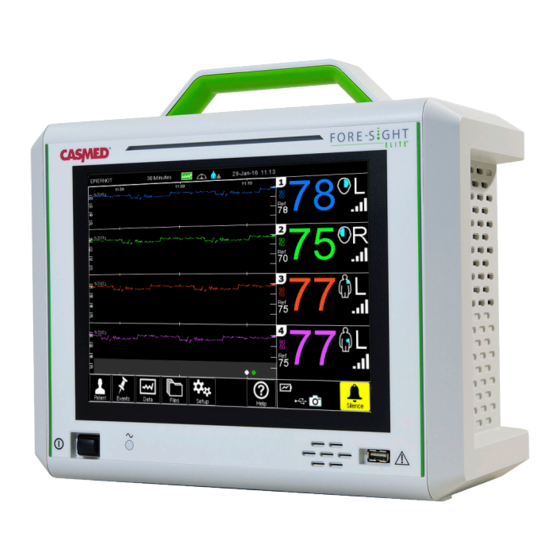
Introduction: About the Oximeter Hardware About the Oximeter Hardware The following diagrams provide an overview of the Oximeter’s physical features. Front View Alarm Indicator (page 35) Display & Touchscreen (page 29) Front USB port (page 16) Power Switch (page 11) Speaker AC Charging Indicator (page 35) -
Page 21: Rear View
FORE-SIGHT ELITE User Manual Rear View Video Out port (page 14) Preamp cable ports Ethernet port (page 13) (CASMED use only) Rear RS-232 USB port Serial ports (page 16) (page 16) Serial Number label Grounding terminal (page 8) Removable Battery... -
Page 22: Side View
Introduction: About the Oximeter Hardware Side View Preamp connections (page 13) Air Intake Vents Preamp Cable Guides (page 13) Figure 4: Oximeter — Left Side View Caution: Keep the air intake vents and exhaust vents (on the right side of the Oximeter) clear of obstructions to allow for proper cooling. -
Page 23: About The Touchscreen Display
FORE-SIGHT ELITE User Manual About the Touchscreen Display Figure 5 shows the main sections of the Oximeter display. See Reading the Oximeter Display on page 29 for further descriptions of each section. Case/Trace Information (page 32) System Message Area (page 35) -
Page 24: Accessing On-Screen Help
Introduction: Accessing On-Screen Help Accessing On-Screen Help From the Main Menu, touch to access the Oximeter’s on-screen help for the following topics: Table 1: On-Screen Help Options Button Description Home Displays the Main Menu. Selection Displays a matrix of appropriate Sensor size by patient weight. Monitoring Displays a list of tasks to complete before monitoring begins. -
Page 25: Installing The Oximeter
Save the damaged shipping carton as evidence. Contact your distributor, CASMED sales representative, or CASMED to report external damage and to arrange for repair or replacement of damaged equipment (see Contact Information on page ii). -
Page 26: Installation Considerations
Installing the Oximeter: Installation Considerations Installation Considerations Installation can be customized to the institution and department’s needs; please contact your local CASMED distributor for assistance. Electrical Connections Warnings: Grounding reliability can be achieved only when the Oximeter is connected to an equivalent receptacle marked “Hospital Grade”. -
Page 27: Physical Placement
(left side) and exhaust vents (right side). Mounting Solutions An optional mounting plate (P/N 01-06-0239) is available for joining the Oximeter with CASMED- approved mounting solutions; the four non-skid feet may also be removed to facilitate installation. -
Page 28: Powering The Oximeter
The Oximeter ships without the Battery installed; before using the Oximeter you should install the Battery as described below, and charge it as described in the following section. Warning: Use only the CASMED Battery that is listed in Accessories, Detachable Parts, and Materials on page 93. -
Page 29: Connecting The Power Cord
FORE-SIGHT ELITE User Manual Connecting the Power Cord The Oximeter ships with a hospital-grade power cord as appropriate for the country and voltage being used. Connect the female end of the cord to the power receptacle on the rear of the Oximeter (Figure 7). -
Page 30: Monitoring Battery Status
Installing the Oximeter: Powering the Oximeter Monitoring Battery Status The battery icon in the lower-right corner of the display indicates the battery’s charge status (Table 2). The Oximeter displays a system alert when the battery is running low to indicate that AC power should be connected. -
Page 31: Testing The Oximeter
Warnings: Inspect the Preamp cable for damage prior to installation. If any damage is noted, it must not be used until it has been inspected by CASMED-authorized personnel and serviced or replaced. There is a risk that damaged parts could reduce the performance of the Oximeter or present a safety hazard. -
Page 32: Figure 10: Attaching The Preamp Cable
Installing the Oximeter: Testing the Oximeter Plug Guide (Side view of Plug Guide, from rear of Oximeter) Cable Guide Figure 10: Attaching the Preamp Cable Figure 11: Disconnecting the Preamp Cable CAS Medical Systems, Inc. -
Page 33: Testing The Oximeter Alarms
FORE-SIGHT ELITE User Manual Testing the Oximeter Alarms CASMED recommends that Alarm operation be tested when the Oximeter is first installed and at least once every 6 months thereafter. To assist with this process, an StO Simulator is available through CASMED. -
Page 34: Interfacing With Other Equipment
The following sections describe the Oximeter interfaces that may be used. Note that the RJ-45 Ethernet port ( ) on the rear of the Oximeter is for CASMED personnel only. Connecting a Second Monitor The Oximeter display can be mirrored onto a second monitor by connecting it to the Oximeter’s Video Out port... - Page 35 FORE-SIGHT ELITE User Manual Note: The Oximeter has one male 9-pin (DTE) DB9 and one female 9-pin (DCE) DB9 Serial Communications Port. Some older units may be shipped with a null modem adapter attached to port A to create a female (DCE) serial port. If the DCE serial port is not required, the null modem adapter may be removed.
-
Page 36: Table 3: Serial Protocol Baud Rate Compatibility Matrix
Touch a Baud Rate to select it or touch to cancel. Table 3 on page 18 shows the compatible baud rates for each protocol. For information on the EMR protocols, see the FORE-SIGHT ELITE EMR Protocol User Guide (CAS P/N 21-03-0368). ✔... -
Page 37: Table 4: Third-Party Solutions
FORE-SIGHT ELITE User Manual Table 4 summarizes the third-party solutions that may interface with the Oximeter. Table 4: Third-Party Solutions Protocol System Required Hardware / Middleware Support Patient Monitoring Systems • • Philips Patient Monitors Philips IntelliBridge EC-10 Module: P/N... - Page 38 Installing the Oximeter: Interfacing with Other Equipment Table 4: Third-Party Solutions Protocol System Required Hardware / Middleware Support Electronic Medical Records (EMR) or Hospital Information Management Systems (HIMS) (Continued) • Evolucare – OpeSIM • Evolucare – Réassist • Fukuda Denshi • GE - QS Perinatal –...
-
Page 39: Monitoring Essentials
haPter Monitoring Essentials This chapter describes the core patient workflow — from connecting the patient to the Oximeter, through the monitoring session, to disconnecting the patient after the session. The following chapter (Additional Monitoring Tasks on page 41) describes other tasks that might be performed during a session. -
Page 40: Selecting The Patient Mode
Monitoring Essentials: Selecting the Patient Mode Selecting the Patient Mode The Oximeter operates in one of two modes, identified by an icon at the top of the screen: Adult Mode Pediatric Mode This mode must be set correctly, as it determines the available Sensor locations (page 44) and, in turn, measurement accuracy. -
Page 41: Attaching Sensors To The Patient
Selecting a Sensor As described in Indications for Use on page xiv: • When used with large Sensors, the FORE-SIGHT ELITE Oximeter is indicated for use on adults and transitional adolescents ≥ 40 kg (88.2 lbs). • When used with Medium Sensors, the FORE-SIGHT ELITE Oximeter is indicated for use on pediatric subjects ≥... -
Page 42: Table 5: Sensor Selection Matrix
✔ location or use a different sensor size. Touch to dismiss the prompt. Warnings: Use only CASMED-supplied accessories with this Oximeter. CASMED accessories ensure patient safety and preserve the integrity, accuracy, and electromagnetic compatibility of the Oximeter. Connecting a non-CASMED... -
Page 43: Preparing The Sensor Site
FORE-SIGHT ELITE User Manual Preparing the Sensor Site To prepare the patient’s skin for Sensor placement: Verify that the skin area where the Sensor is to be placed is clean, dry, intact, and free of powder, oil, or lotion. If necessary, shave hair from skin at the chosen site. -
Page 44: Figure 16: Applying Sensors (Cerebral)
Monitoring Essentials: Attaching Sensors to the Patient Affix the Sensor to the patient in the chosen location. • Cerebral Use (Figure 16): Select the site on the forehead above the eyebrow and just below the hairline where the Sensors will be linearly aligned. Non-Adhesive Small Sensor Figure 16: Applying Sensors (Cerebral) -
Page 45: Figure 17: Sensor Placement (Non-Cerebral)
FORE-SIGHT ELITE User Manual adult pediatric/neonatal Non-Adhesive Small Sensor Figure 17: Sensor Placement (Non-Cerebral) PN 21-22-3000 Rev 07... -
Page 46: Connecting Sensors To The Preamp Cables
Monitoring Essentials: Attaching Sensors to the Patient Connecting Sensors to the Preamp Cables Be sure that all necessary Preamp cables are fully connected and that Sensors are placed correctly on the patient’s skin. Use the clips on the Preamp cable to secure it to prevent the cable or Preamp from being pulled away from the patient. -
Page 47: Reading The Oximeter Display
FORE-SIGHT ELITE User Manual Reading the Oximeter Display The Oximeter has a touchscreen display that displays patient monitoring data and provides access to on-screen Oximeter functions. Figure 20 shows the primary areas of the display. Case/Trace Information (page 32) System... -
Page 48: Reading The Channel Display
Monitoring Essentials: Reading the Oximeter Display Reading the Channel Display Figure 21 shows a sample Channel 2 Status display as it would appear in a 2-Channel monitoring session; the channel in a 4-Channel session would contain the same components, displayed in half the vertical space. -
Page 49: Monitoring Tpi
FORE-SIGHT ELITE User Manual Monitoring TPI The Tissue Perfusion Index (TPI) indicator represents the amount of hemoglobin in the tissue under a Sensor and is graphically represented near the StO value (see Table 7). The TPI level is useful for assessing a Sensor site and should be 3 to 4 bars in normal operation. -
Page 50: Reading The Trace Display
Monitoring Essentials: Reading the Oximeter Display Reading the Trace Display Figure 22 shows a sample upper Trace Display for a 4-channel monitoring session. Data Collection Active Averaging Patient Mode (page 59) Speed (page 22) (page 22) Trace View/Scale Date & Time Time reference (page 52) (page 54) -
Page 51: Capturing The Oximeter Display
To save a snapshot of the Oximeter display: Insert a CASMED-approved USB flash drive into one of the two USB ports; you may use either the front or rear USB port, though only one may be active at a time. -
Page 52: Starting A New Case
Monitoring Essentials: Starting a New Case Starting a New Case The Oximeter collects and saves patient data continuously into individual files that can be downloaded and analyzed (see Managing Patient Data Files on page 61). When a new patient case is started, the following events occur: •... -
Page 53: Responding To Alarms And Messages
FORE-SIGHT ELITE User Manual Responding to Alarms and Messages Visual Alarms When an alarm condition occurs, or when a system (Indicator bar) message is generated, the Oximeter may signal it with both auditory and visual indicators, depending on the type of alarm/message and its priority (Figure 25). -
Page 54: Checking Sensors
Setting the Skin Check Timer on page 55. CASMED recommends that the Skin Check timer should always be enabled. Touch a new Skin Check interval to select it and reset the timer, touch Reset to reset the ✘... -
Page 55: Monitoring Considerations
No separate actions are required when using this equipment with a defibrillator, but only CASMED-supplied Preamp cables and Sensors must be used for proper protection against the effects of a cardiac defibrillator. Do not come into contact with patients during defibrillation, or serious injury or death could result. -
Page 56: Interpreting Sto
Unlike the other FORE-SIGHT ELITE validation studies, this cerebral validation study did not include invasive measurements because of the challenge for medical centers to obtain consent to insert an internal jugular venous catheter in very small subjects. data was averaged in two-minute windows for term, premature low birth weight (LBW), and very low birth weight (VLBW) neonates for... -
Page 57: Disconnecting Sensors After Monitoring
FORE-SIGHT ELITE User Manual Measurement Accuracy Cerebral Accuracy Accuracy (Bias ± Precision) not determined outside the following ranges: Large Sensors: 45% to 95%: -0.14 ± 3.05% at 1 SD Medium Sensors: 48% to 92%: 0.05 ± 5.06% at 1 SD Small Sensors: 50% to 90%: -0.01 ±... - Page 58 Monitoring Essentials: Disconnecting Sensors After Monitoring CAS Medical Systems, Inc.
-
Page 59: Additional Monitoring Tasks
haPter Additional Monitoring Tasks This chapter describes optional tasks (those not part of the core workflow) that you might perform during a monitoring session. Entering a Patient ID Patient IDs are optional. If entered, it appears on the left side of the display, above the Trace area. -
Page 60: Resetting The Reference Level
Additional Monitoring Tasks: Resetting the Reference Level Resetting the Reference Level When StO readings are first detected for a new patient, a reference level for each active channel is automatically set and displayed in the lower left corner of each Channel Status area. Reference values are preserved for the duration of a patient case, until a Sensor location is changed, or until another Reference level is set. -
Page 61: Configuring Channel Settings
FORE-SIGHT ELITE User Manual Configuring Channel Settings In many cases you can run a monitoring session without modifying the default channel settings, which are shown in Table 10: Table 10: Default Channel Settings Channel Body Location High Limit Low Limit... -
Page 62: Configuring The Sensor Location
Additional Monitoring Tasks: Configuring Channel Settings Configuring the Sensor Location Note: The Sensor location setting is used for measurement accuracy, and should be set correctly. To change the Patient Mode, see page 22. To change a channel’s Sensor location: Access the Patient Setup options by touching a location icon or numeric in the Channel Status area. -
Page 63: Configuring Sto
FORE-SIGHT ELITE User Manual Configuring StO Alarm Limits limits (both low and high) can be set independently for each channel. The default values are 50% (low) and 90% (high), and any StO reading outside that range will trigger an alarm. -
Page 64: Marking Events
Additional Monitoring Tasks: Marking Events Marking Events This section how to add events to the Trace view, how to navigate the event area, and how to create and manage custom events. Placing Event Markers During the course of a monitoring session, medical procedures or other events that occur may affect StO levels. -
Page 65: Navigating The Event Area
FORE-SIGHT ELITE User Manual ✘ Touch an event to place it, or touch to cancel. Once placed, a marker is placed at the lower-right corner of the Trace area (that is, at the current time). Marker colors correspond to the Event colors. If you select the wrong event... -
Page 66: Viewing The Event Log
Additional Monitoring Tasks: Marking Events ✘ To move the Event Navigator, touch and drag the panel to a new location; touch to close it. Table 12: Event Navigator Functions Button Description Moves the cursor in either direction by 1 pixel (approximately 4 seconds, based on the 30-minute Trace View default;... -
Page 67: Creating Custom Events
FORE-SIGHT ELITE User Manual Creating Custom Events In addition to the main event lists (OR, ICU, PICU, and Vascular), you can create and manage a list of custom events. (To import a new or existing set of events, see Importing Custom Events on page 51.) -
Page 68: Editing Custom Events
Additional Monitoring Tasks: Marking Events ✔ Add additional events as needed; touch when you are done adding events. When you place a custom event (touch Events and then touch Custom), the Custom Events screen allows you to choose from the configured events: Editing Custom Events To edit a custom event name from the Oximeter: From the Main Menu, touch... -
Page 69: Exporting Custom Events
Custom Events on page 51) that you can edit offline or import into other Oximeters. To export custom events: Insert a CASMED-approved USB flash drive into the USB port. Verify that the USB icon ( ) is displayed in the lower-right corner of the display. -
Page 70: Adjusting Display Settings
Additional Monitoring Tasks: Adjusting Display Settings Adjusting Display Settings This section describes some of the Oximeter display settings that you may adjust. Changing the Trace View Scale The time scale for the Trace area is displayed above the Trace area, and is set at 30 minutes by default. -
Page 71: Setting The Display Language
FORE-SIGHT ELITE User Manual Setting the Display Language The Oximeter’s default language is English but can be changed as necessary. Note that, if the Oximeter is reset to factory default settings, that the language setting will not be affected. From the Main Menu, touch Setup. -
Page 72: Setting The Time And Date
Additional Monitoring Tasks: Marking Events Setting the Time and Date The Oximeter displays the Time and Date at the top of the display at all times, and the Trace View’s time markers change to maintain a consistent time reference at the selected scale. The Time and Date settings are also used to name patient data files and in recording patient data and statistics. -
Page 73: Setting The Skin Check Timer
If disabled, the Skin Check option will not appear on the Patient menu. Note: CASMED recommends that the Skin Check timer should always be enabled. If you enable or disable the Skin Check timer (non-Off selection to Off, or Off to non-Off selection) the Oximeter will automatically power off and restart. -
Page 74: Enabling The Extended Averaging Menu
Additional Monitoring Tasks: Marking Events Enabling the Extended Averaging Menu The standard StO Averaging modes (see page 22) are Fast, Normal, and Slow. You may enable the extended averaging menu to display a fourth mode, None, which uses the fastest response available. -
Page 75: Configuring Auditory Feedback
FORE-SIGHT ELITE User Manual Configuring Auditory Feedback The system volume defaults to 100%, and affects system sounds (such as button clicks) as well as auditory alarms. You can adjust the volume if necessary, and can configure a delay during which auditory alarms will not sound. -
Page 76: Setting The Alarm Delay
Additional Monitoring Tasks: Configuring Auditory Feedback Setting the Alarm Delay By default, when the Oximeter detects an alarm condition or generates a system message that is tied to an auditory alarm, it responds instantly and sounds the appropriate alarm (see Appendix B, Alarms and Messages on page 73 for a list of conditions that may trigger an auditory alarm). -
Page 77: Managing Patient Data
haPter Managing Patient Data This chapter describes STS Data collection and how to copy patient data files from the Oximeter to a USB flash drive. Collecting STS Data The Oximeter is able to collect data for The Society of Thoracic Surgeons (STS) reporting, which is saved and downloaded with the normal monitoring data for each patient case file (see Managing Patient Data Files on page 61). -
Page 78: Viewing Sts Data
Managing Patient Data: Viewing Trend Data Viewing STS Data You may view a snapshot of the STS data being collected during a monitoring session either during collection or after collection has stopped. To view current STS data: Touch the icon at the top of the screen to display STS Data. Data and then touch View. -
Page 79: Managing Patient Data Files
To copy a file from the Oximeter to a USB flash drive: Insert a CASMED-approved USB flash drive into one of the two USB ports; you may use either the front or rear USB port, though only one may be active at a time. -
Page 80: Deleting Data Files From The Oximeter
Managing Patient Data: Managing Patient Data Files Deleting Data Files from the Oximeter To delete a patient file from the Oximeter: From the Main Menu, touch Files. The Oximeter displays a list of patient data files in memory. The Patient ID column displays the patient name or patient identifier, if entered: Touch one or more files to select them. -
Page 81: Cleaning And Maintaining The Oximeter
If any damage is noted, the Oximeter or accessory must not be used until it has been inspected and serviced or replaced by CASMED-authorized personnel. The parts of the Oximeter include the Monitor, Preamp cable(s), Battery, AC power cord and Sensor(s). -
Page 82: Cleaning The Oximeter
Liquids must not be allowed to enter the device. There is a risk of electric shock or device malfunction if liquids enter a device. Detach any USB drives before cleaning. Caps and plugs for unused ports may be obtained from CASMED. A USB Plug Kit (P/N 01-06-3020) is available from your CASMED distributor. -
Page 83: Testing Alarm Operation
FORE-SIGHT ELITE User Manual Testing Alarm Operation CASMED recommends that Alarm operation should be tested when the Oximeter is first installed and at least once every 6 months thereafter. An StO Simulator is available through CASMED. Connect the StO Simulator to the patient connection of the Oximeter (where a Sensor would normally be attached;... -
Page 84: Installing The Battery
Cleaning and Maintaining the Oximeter: Replacing the Battery Installing the Battery Warning: Use only the CASMED Battery that is listed in Parts on page 93. Ensure that the AC power cord is not connected to the Oximeter. Position the Battery near the Battery compartment with the arrow on the outside cover pointing up (see Figure 32 on page 65). -
Page 85: Replacing The Ac Fuses
See Specifications on page 89 Other fuses located inside the Oximeter and Battery are not user-replaceable, and must be replaced only by CASMED-authorized Service personnel. To replace the AC power fuses: Turn the Oximeter off, disconnect the AC power cord, and remove the Battery as described on page 65. -
Page 86: Resetting The Oximeter To Factory Settings
Cleaning and Maintaining the Oximeter: Resetting the Oximeter to Factory Settings Resetting the Oximeter to Factory Settings If you should need to restore the Oximeter’s factory defaults, you can do so from the Setup menu. The following settings are not affected by a reset: •... -
Page 87: Menu Reference
PPendix Menu Reference This appendix describes each of the Oximeter menus and provides a reference to the relevant section where applicable. Main/Home Menu Table 14: Main Menu Options Button Description Patient Lets you start a new case, configure Sensor Table 15 on page 70 location and high/low oxygen thresholds for a patient, and enter a patient ID. -
Page 88: Table 15: Patient Menu Options
Menu Reference Patient Menu Table 15: Patient Menu Options Button Description Page Home Displays the Main Menu. — Setup Lets you specify the body location for each Sensor and the page 43 High/Low StO limits. Patient ID Lets you enter a Patient ID, which is shown on the Oximeter page 41 display and used to identify patient data files. -
Page 89: Table 17: Data Menu Options
FORE-SIGHT ELITE User Manual Data Menu Table 17: Data Menu Options Button Description Page Home Displays the Main Menu. — Stop / Start Stops Patient Data collection for comparison to the page 59 STS database; touch the button again to restart data collection. -
Page 90: Table 19: Help Menu Options
Menu Reference Table 18: Setup Menu Options Button Description Page Biomed Submenu Page 1 (via Setup > Log In) Home Displays the Main Menu. — Language Sets the display language. page 53 Ports Lets you configure the serial ports and baud rates page 16 for communicating with third-party solutions. -
Page 91: Alarms And Messages
PPendix Alarms and Messages This Appendix describes the Oximeter Alarms and Messages • System Messages (page 74) • Channel Messages (page 76) • Philips Patient Monitor Messages (page 78) PN 21-22-3000 Rev 07... -
Page 92: Table 20: Oximeter System Messages
Condition Recommended Actions Medium Priority Alarms (Black on Yellow) – in priority order System Error E## Internal component failure; ## If condition persists, contact CASMED indicates type of Error technical support Depleted Battery Battery needs to be recharged Plug Oximeter into AC outlet... - Page 93 FORE-SIGHT ELITE User Manual Table 20: Oximeter System Messages Message Condition Recommended Actions Faulty System Fan Operation of fan faulty Check for free flow of temperate air around Oximeter Move Oximeter away from wall or other obstruction Move it to a cooler area...
-
Page 94: Table 21: Oximeter Channel Messages
Medium Priority Alarms (Black on Yellow) – in priority order Faulty Preamp Preamp cable is defective If condition persists, contact CASMED to replace the Preamp cable (see page ii) Preamp Preamp cable has become... - Page 95 FORE-SIGHT ELITE User Manual Table 21: Oximeter Channel Messages Message Condition Recommended Actions Signal out of Sensor on inappropriate object Remove Sensor from inappropriate object and Range place on patient Check under Tissue under Sensor may have fluid Check patient for edema under Sensor...
-
Page 96: Table 22: Oximeter Messages Displayed On Philips Patient Monitors
Alarms and Messages Philips Patient Monitor Messages • Only High, Medium, and Low Priority System and Channel Alarm Messages Notes: are displayed on Philips Patient Monitors. • Oximeter Alarm Messages may appear different on the Philips Patient Monitors due to text length limitations. Table 22: Oximeter Messages Displayed on Philips Patient Monitors Oximeter Message Philips Message... -
Page 97: Event Index
PPendix Event Index The tables in this Appendix list the predefined events that can be placed onto a trace during a monitoring session. There are four event lists to choose from: • OR Events • CCU Events • PICU Events •... -
Page 98: Table 23: Event Menus By Category
Event Index Table 23: Event Menus by Category OR Events CCU Events PICU Events Vascular Events Cannulation Enteral Feeding Blood Gas Cannulation Cardioplegia Extubation Cooling Start Clamp Off Vessel Closing Sternum Intubation Diaper Change Clamp On Vessel Cooling Apnea Enteral Feeding Decannulation CPB On/Off Arrhythmia... -
Page 99: Symbol Reference
PPendix Symbol Reference The following tables summarize the symbols used on the Oximeter and its accessories. Symbols may appear on the product or on its packaging. Symbols are black unless otherwise indicated. Oximeter Case Table 24: Symbols on the Oximeter Case Symbol Description Front... -
Page 100: Table 25: Symbols On The Oximeter Display
Symbol Reference Table 24: Symbols on the Oximeter Case Symbol Description Video port, VGA Connector Ethernet port, RJ-45 Connector Follow instructions for use (white on blue) Oximeter Display See Appendix A, Menu Reference, on page 69 for Oximeter menu icon descriptions. Table 25: Symbols on the Oximeter Display Symbol Description... - Page 101 FORE-SIGHT ELITE User Manual Table 25: Symbols on the Oximeter Display Symbol Description Sensor Patient Mode determines the available Sensor Adult Pediatric Locations locations. Left Brain (frontal lobe) ✔ ✔ Right Brain (frontal lobe) ✔ ✔ Left Shoulder (deltoid) ✔...
- Page 102 Symbol Reference Table 25: Symbols on the Oximeter Display Symbol Description NONE (four Gray bars) No Sensor or Preamp connected or Indicators Sensor and Preamps connected, but Sensor off patient POOR (one White bar & three Gray bars) Indicates that the Sensor should be moved as monitoring will soon stop;...
-
Page 103: Table 26: Symbols On The Battery
FORE-SIGHT ELITE User Manual Table 25: Symbols on the Oximeter Display Symbol Description Event Step forward one pixel Navigator Step forward five pixels Step backward one pixel Step backward five pixels Skip to next event Skip to next event, disabled (if there are no visible events) -
Page 104: Table 27: Symbols On The Oximeter Packaging
Symbol Reference Oximeter Packaging Table 27: Symbols on the Oximeter Packaging Symbol Description Symbol used to indicate the minimum and maximum storage and transport Temperatures. Refer to Storage/Transport Environment on page 90 Symbol used to indicate the minimum and maximum relative humidity for storage and transport. -
Page 105: Table 30: Symbols On The Sensor Packaging
FORE-SIGHT ELITE User Manual Sensor Packaging Table 30: Symbols on the Sensor Packaging Symbol Description Federal law restricts this device to sale by or on the order of a physician or licensed practitioner (USA only) Caution Follow instructions for use... - Page 106 Symbol Reference: CAS Medical Systems, Inc.
-
Page 107: Specifications
PPendix Specifications Physical Dimensions and Weight H × W × D: (without feet) 11.5 in (29.2 cm) × 12.9 in (32.7 cm) × 6.7 in (17.0 cm) Weight: 13.3 lbs (6.0 kg) Operating Environment Operating temperature: 10°C (50°F) to 40°C (104°F) Humidity: 15 to 75% RH, non-condensing Altitude:... - Page 108 Specifications Non-Cerebral Accuracy: Accuracy (Bias ± Precision) not determined outside the following ranges: Large Sensors: 45% to 95%: 0.24 ± 5.17% at 1 SD Medium Sensors: 53% to 88%: -0.03 ± 5.52% at 1 SD Small Sensors: 66% to 96%: 0.03 ± 5.69% at 1 SD Patient Alarms Adjustable alarms: High, Low limits for Ch1, Ch2, Ch3, &...
- Page 109 FORE-SIGHT ELITE User Manual Power External AC power: 100 to 240 VAC, 50/60 Hz, 1.5A Max (1.5A to 0.75A) Fuse rating: T3.15AH250V (two provided) Chassis leakage current: 100 µA (maximum) Heat dissipation: 60 watts (205 BTU/hr) Battery: Sealed lead-acid battery...
- Page 110 Specifications Standards Compliance The FORE-SIGHT ELITE Oximeter complies with the following requirements: CE marking according to Directive 93/42/EEC IEC 60601-1 IEC 60601-1-2 IEC 60601-1-6 IEC 60601-1-8 CAN/CSA C22.2 #60601-1 ANSI/AAMI ES60601:2005 CAS Medical Systems, Inc.
-
Page 111: Parts
PPendix Parts Contact the CASMED Customer Service department (see Contact Information on page ii) or visit www.casmed.com for the latest product information. Oximeter Table 31: Oximeter Models Catalog No. Description 01-06-3000 (1) FORE-SIGHT ELITE Oximeter All Oximeter models come with: •... -
Page 112: Table 33: Philips Accessories
01-07-2102 FORE-SIGHT ELITE Medium Sensor Carton (20 Sensors) 01-07-2101 FORE-SIGHT ELITE Small Sensor Carton (20 Sensors) 01-07-2100 FORE-SIGHT ELITE Non-Adhesive Small Sensor Carton (10 Sensors) 01-06-0232 FORE-SIGHT 3-inch Utility Basket for 01-06-0234, 01-06-0235 or 01-06-0236 Arms 01-06-0233 FORE-SIGHT 6-inch Utility Basket for 01-06-0234, 01-06-0235 or... -
Page 113: Warranty Policy
Buyer’s sole and exclusive remedy under the above warranties is limited to repairing or replacing, free of charge, a product which is reported in writing or via telephone to CASMED has a Return Material Authorization (RMA) number assigned and which is returned during normal... - Page 114 CASMED, unless disclosure is required by law. CASMED will erase all stored patient data prior to the return of the repaired unit. CAS MEDICAL SYSTEMS, INC. SHALL NOT BE OTHERWISE LIABLE FOR ANY DAMAGES INCLUDING, BUT NOT LIMITED TO, INCIDENTAL DAMAGES, CONSEQUENTIAL DAMAGES OR SPECIAL DAMAGES.
- Page 115 Buyer’s sole and exclusive remedy under the above warranties is limited to repairing or replacing, free of charge, a product which is reported in writing or via telephone to CASMED has a Return Material Authorization (RMA) number assigned and which is returned during normal...
- Page 116 CASMED, unless disclosure is required by law. CASMED will erase all stored patient data prior to the return of the repaired unit. CAS MEDICAL SYSTEMS, INC. SHALL NOT BE OTHERWISE LIABLE FOR ANY DAMAGES INCLUDING, BUT NOT LIMITED TO, INCIDENTAL DAMAGES, CONSEQUENTIAL DAMAGES OR SPECIAL DAMAGES.
-
Page 117: Index
13 serial devices 16 disconnecting 15 USB device 16 electrical connections 8 case, starting 34 considerations electromagnetic interference 8 CASMED flammable substance 37 environment xvi parts 93 monitoring 37 equipment, optional 16 parts and warranty xvii considerations, installation specifications 89... - Page 118 Index Event Log 48 measurement accuracy xv diagrams 2–4 disconnecting Sensors 39 events 79 menus 69 display, overview 5 CCU 80 Biomed 72 factory settings 68 color codes 46 Data 71 front view 2 cursor 47 Events 70 hardware 2 custom.
- Page 119 FORE-SIGHT ELITE User Manual serial 16 preparing site 25 viewing 60 USB 16 selecting site 23 substance, flammable 37 video 16 selecting size 23 symbols selection matrix 24 power battery pack 85 Skin Check timer 36 connecting cord 11 Oximeter case 81...
- Page 120 44 EAST INDUSTRIAL ROAD BRANFORD CT 06405 800.227.4414 WWW.CASMED.COM PN 21-22-3000 Rev 07...
Need help?
Do you have a question about the fore-sight elite and is the answer not in the manual?
Questions and answers