Table of Contents
Advertisement
Application Guide
XL19i-APG02-EN
Low Outdoor Operating Temperature
Minimum Clearances
Refrigerant Piping Limitations
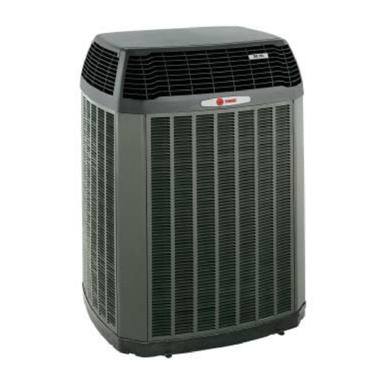
Trane XL19i heat pumps and cooling units
Advertisement
Table of Contents

Related Manuals for Trane XL19i-APG02-EN


Summary of Contents for Trane XL19i-APG02-EN
- Page 1 Application Guide XL19i-APG02-EN Low Outdoor Operating Temperature Unit Mounting Minimum Clearances Refrigerant Piping Limitations Trane XL19i heat pumps and cooling units...
- Page 2 The purpose of this bulletin is to provide cumulative application criteria as related to the Trane XL19i cooling units and heat pumps. This bulletin discusses: Off Season Cooling Operation II. Unit Mounting III. Minimum Operating Clearances IV. Refrigerant Piping Limitations...
- Page 3 Section I - Off Season Cooling Operation The Trane XL19i may be operated in the cooling mode to 45 F as shipped from the factory. These units shall only be matched with variable speed air handling units and variable speed furnace / coil combinations.
- Page 4 Typical wiring when using the evaporator defrost control (EDC) for operation as specified on page 3. Cooling Split System and AY28X079 Evaporator Defrost Control Thermostat TWE-E 2 T T Z 9 Y low Green (G) White (W1) White (W2) White (W3) Blue (B) Heat Pump Split System and AY28X084 Evaporator Defrost Control Thermostat...
- Page 5 This section describes appropriate methods for mounting and securing the XL19i. However, if these units are to be mounted in a region where high winds are an issue, please refer to the Trane BAYECMT001 extreme conditions mounting kit. If seizmic restraint is required, please refer local code authority. This application may require a local P.E.’s approval and stamp.
- Page 6 2” from the basepan perimeter support center of unit If supporting the base pan from the perimeter, the support must extend under the base pan at least 2”. Trane recom- mends supporting the middle of the base pan with a cross member.
- Page 7 Section III - Minimum Operating Clearances This section discusses applying a condensing unit / heat pump in installations where there are space constraints. These concerns must be addressed: 1. System Operation - Adequate airflow must be provided to the condensing unit / heat pump in order to enable appropriate heat transfer.
- Page 8 Consult with local building department to assure the installation will comply with local code before installing the equipment. Illustrations provided to designate required clearances. Trane recommendeds mounting the unit on a pad that is independent of the structure. Reference section III.A.1.F on pg 8 of this document.
-
Page 9: Front View
2’ feet maximum 3’ minimum overhang from from top of side of unit to deck. unit to deck Outdoor Unit 3’ Minimum clearance from 2 sides of unit to walls Front View 3’ minimum from 2’ maximum side of unit to deck overhang wall of home to side of unit... - Page 10 TOP VIEW ISOMETRIC VIEW Illustrations provided to designate required clearances. Trane recommendeds mounting the unit on a pad that is independent of the structure. Reference section III.A.1.F on Pg 8 of this document. Pg. 10...
- Page 11 2. Single XL19i condensing unit / heat pump in a corner with unrestricted top clearance A) For locations where the design ambient temperature is below 105F: 1) 1.5 feet clearance from both walls. 2) Other two sides left unrestricted B) For locations where the design ambient temperature exceeds 105F: 1) 2.0 feet clearance from both walls.
- Page 12 4. Single XL19i condensing unit / heat pump in a fenced corner with unrestricted top clearance A) For locations where the design ambient temperature is below 105F: 1) 1.5 feet clearance from both walls. 2) 2.0 feet fence clearance - openings shall be provided to allow free air passage to unit. ( Free air passage shall be sized @ 300 FPM Velocity) 3) Service access shall be 3.0 feet minimum B) For locations where the design ambient temperature exceeds 105F:...
- Page 13 5. Installation of two or more XL19i units where two adjacent walls form a fenced corner A) For locations where the design ambient temperature is below 105F: 1) Corner unit shall have1.5 feet clearance from one wall and 2.0 feet clearance from the other wall. 2) 3.0 feet clearance in between units.
- Page 14 D) Fence construction. 1) Height shall not exceed the top of the unit. 2) Free air passages shall be size at no greater than 300 FPM velocity. 3) Free air passages shall be cut at the lower portion of the fence. 4) Fence may also be undercut to allow free air passage provided grass, vegetation, or debris will not obstruct the free air passage.
- Page 15 Table 110.26 as well as the figures beside the table describe the minimum clearance for proper service and access to electrical equipment. Trane residential and light commercial condensing units ranging from 1 to 6 ton require access to the side service panel as indicated on the previous pages to gain access to the electrical controls.
- Page 16 f r i i l o s t i s t i *Table produced Jan. 2003. For the most current information, please refer to specific equipment Product Data. Required Opening = CFM / 300 FPM Example: Given: Qty of 2 units in an area surrounded by a fence on two sides and solid walls on the other two sides. Units are 2TTZ9030A100A’s - Required: Determine free air opening space required in fence -...
- Page 17 XL19i Unit Dimensions " 8 " 4 " 4 " 8 " 4 " 4 " 8 " 4 " 4 " 8 " 4 " 4 " 8 " 4 " 4 " 8 " 4 " 4 " 8 "...
- Page 18 Section IV - Refrigerant Piping A. Purpose 1. Liquid line - The purpose of the liquid refrigerant line is to convey refrigerant, in the liquid state, from the outdoor unit to the indoor unit in the cooling mode and from the indoor unit to the outdoor unit in the heating mode.
- Page 19 NOTES Pg. 19...
- Page 20 Literature Order Number Trane File Number XL19i-APG02-EN 03/04 6200 Troup Highway Supersedes XL19i-APG01-EN 01/03 Tyler, TX 75707 http://www.trane.com Stocking Location Since Trane has a policy of continuous product improvement, it reserves the right to change design and specifications without notice...
Need help?
Do you have a question about the XL19i-APG02-EN and is the answer not in the manual?
Questions and answers