
Summary of Contents for Pfeiffer DCU 001
-
Page 1: Manufacturer's Declaration
Operating Instructions DCU 001 DCU 100 DCU 150 DCU 200 DCU 300 DCU 600 Display And Operating Unit... -
Page 2: Table Of Contents
Index Page Safety Instructions ....................3 Understanding The Control And Operating Unit DCU ........4 2.1. For Your Orientation ......................... 4 2.2. Product Description......................... 4 Scope of Delivery ..........................4 Mechanical Design.......................... 4 Connection Options.......................... 5 Proper Use............................5 Improper Use ............................ 5 2.3. -
Page 3: Safety Instructions
1. Safety Instructions ☞ Read and follow all instructions in this manual. ☞ Inform yourself regarding – Dangers which can arise from the unit; – Dangers which can arise from the system; ☞ Follow the safety and accident prevention instructions. ☞... -
Page 4: Understanding The Control And Operating Unit Dcu
– Electronic drive unit for turbopump (X2) – Pressure gauge (X3). – Serial interface RS 485. The units DCU 001, DCU 100 - DCU 600 have been tested and passed by the authorities in accordance with EN 61010/VDE 0411 “Safety Equipment For Electrical Units”. -
Page 5: Proper Use
Proper Use – The display and operating unit DCU may only be used to control PFEIFFER Electronic Drive Units and their peripheral units. – Instructions concerning installation, start-up, operating and maintenance must be observed. Improper Use Improper is: – Uses not covered above, especially: –... -
Page 6: Rear Panel
Mains connection 90-265 V~ unit Output for voltage supply, electronic drive unit Pressure gauge connection 10AF RS 485 Communication with electronic drive unit 10AF Pressure gauge connection DCU 001 without mains power RS 485 Communication with electronic drive unit unit... -
Page 7: Installation
A A i i r r p p r r e e s s s s u u r r e e : : 86 kPa - 106 kPa 3.2. Rack Fitting The units DCU 001, DCU 100 - DCU 600 are designed to be fitted into a 19”/3HE rack with guide rails. ➡... -
Page 8: Making The Connections
Make the connection RS 485/DCU-RS 485/Electronic Drive Unit via the delivered 8 pole cable. The DCU 001 is re-supplied with its operating voltage via the Serial Interface RS 485 cable from the Electronic Drive Unit. As soon as this unit is switched on, the DCU is supplied with voltage. -
Page 9: General
The value of the parameter is always readable, in some cases also modifiable via the keyboard. 4.3. Switching On The Control Unit ➡ Make the connection to the Serial Interface RS 485. DCU 001: ➡ Switch on the external supply of the Electronic Drive Unit (for example TPS 100-600). DCU 100/150/200/300/600: ➡... -
Page 10: Functions Of The Keys
4.4. Functions Of The Keys The four keys on the front panel have the following functions: Application/Example Explanation R R e e s s e e t t (error acknowledgement). Acknowledges errors (red LED illuminates) 309: Act rotspd S S c c r r o o l l l l b b a a c c k k p p a a r r a a m m e e t t e e r r s s 310: TMP I-Mot Scrolls back a parameter –––>... -
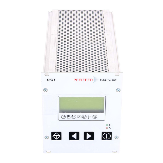
Page 11: Lc-Display
4.5. LC-Display Line 1 721: Vent time 120 s Line 2 Line 3 Line 4 Symbols The functions are displayed via a four line LC display. A special function is assigned to each line – L L i i n n e e 1 1 : : Number and name of the selected parameter (for example 721: >>Vent time<<). –... -
Page 12: Symbol Definitions
4.6. Symbol Definitions Symbol Arrow Explanation Pump – accelerates Pre-selection – No pre-selection heating Pre-selection heating, but switchpoint not attained Heating ON, switchpoint attained Stand-by – Unit under – remote control Switchpoint – attained Excess- – No excess temperatures temperature Excess temperature pump Excess temperature pump elektronik Excess temperature pump and... -
Page 13: Led Display
P P o o s s s s i i b b l l e e a a c c t t i i o o n n • Wrong pump identification resistance • Mains OFF-ON ** Error E021 ** • Inform PFEIFFER-Service • Hardware error: external RAM defective • Inform PFEIFFER-Service ** Error E040 ** •... -
Page 14: What To Do In Case Of Breakdowns
In the event that repairs are necessary a number of options are available to you to ensure any system down time is kept to a minimum: – Have the unit repaired on the spot by PFEIFFER Service Engineers; – Return the unit to the manufacturer for repairs;... -
Page 15: Data List
Air pressure: 86kPa - 106 kPa Protection type: IP 20 Weight: 1) only supplied by PFEIFFER Electronic Drive Unit 2) at 90-132 V AC / 185-265 V AC 3) non condensing 8.2. Dimesions DCU 001/100-600 D D C C U U 0 0 0 0 1 1 D D C C U U 1 1 0 0 0 0 ..3 3 0 0 0 0... -
Page 16: Supplementary Informations
(please see the table). If, despite every effort by us, information on your products is missing please get in touch with your local Pfeiffer representatives or call us on the hotline shown on the back cover page. All operating instructions are also available as PDF files at www.pfeiffer-vacuum.net. - Page 17 Notizen / Notes...
- Page 18 C C o o m m p p a a t t i i b b i i l l i i t t y y D D i i r r e e c c t t i i v v e e 8 8 9 9 / / 3 3 3 3 6 6 / / E E E E C C and E E U U L L o o w w V V o o l l t t a a g g e e D D i i r r e e c c t t i i v v e e 7 7 3 3 / / 2 2 3 3 / / E E E E C C . Produkt/ Product : DCU 001, DCU 100, DCU 200, DCU 300, DCU 600 Angewendete Richtlinien, harmonisierte Normen und angewendete, nationale Normen:...
- Page 20 Dry Vacuum Pumps Leak Test Units Valves Flanges, Feedthroughs Vacuum Measurement Gas Analysis System Technology Service Pfeiffer Vacuum Technology AG · Headquarters/Germany Tel. +49-(0) 64 41-8 02-0 · Fax +49-(0) 64 41-8 02-2 02 · info@pfeiffer-vacuum.de www.pfeiffer-vacuum.net 2 2 0 0...
Need help?
Do you have a question about the DCU 001 and is the answer not in the manual?
Questions and answers