
Related Manuals for Acer ASPIRE ASPIRE X1700


Summary of Contents for Acer ASPIRE ASPIRE X1700
- Page 1 Acer Aspire X1700 and Veriton X270 Service Guide Service guide files and updates are available on the ACER/CSD web; for more information, please refer to http://csd.acer.com.tw PRINTED IN TAIWAN...
-
Page 2: Revision History
Revision History Please refer to the table below for the updates made on this service guide. Date Chapter Updates... - Page 3 Copyright Copyright © 2008 by Acer Incorporated. All rights reserved. No part of this publication may be reproduced, transmitted, transcribed, stored in a retrieval system, or translated into any language or computer language, in any form or by any means, electronic, mechanical, magnetic, optical, chemical, manual or otherwise, without...
- Page 4 Any Acer Incorporated software described in this manual is sold or licensed "as is". Should the programs prove defective following their purchase, the buyer (and not Acer Incorporated, its distributor, or its dealer) assumes the entire cost of all necessary servicing, repair, and any incidental or consequential damages resulting from any defect in the software.
- Page 5 Conventions The following conventions are used in this manual: SCREEN MESSAGES NOTE WARNING CAUTION IMPORTANT Denotes actual messages that appear on screen. Gives additional information related to the current topic. Alerts you to any physical risk or system damage that might result from doing or not doing specific actions.
- Page 6 Service Guide. For ACER-AUTHORIZED SERVICE PROVIDERS, your Acer office may have a DIFFERENT part number code to those given in the FRU list of this printed Service Guide. You MUST use the list provided by your regional Acer office to order FRU parts for repair and service of customer machines.
-
Page 7: Table Of Contents
Table of Contents System Tour Features System Components Front Panel Rear Panel Internal Components System LED Indicators System Utilities CMOS Setup Utility Entering CMOS setup Navigating Through the Setup Utility Setup Utility Menus System Disassembly Pre-disassembly Procedure Main Unit Disassembly X1700 model X270 model Screw List... - Page 8 FRU (Field Replaceable Unit) List Exploded Diagram X1700 X270 X1700 FRU List (81.3V401.007G) X270 FRU List (91.3V401.006G) Technical Specifications viii...
-
Page 9: System Tour
System Tour Features Below is a brief summary of the Aspire X1700 and Veriton X270 computer’s many feature: NOTE: The features listed in this section is for your reference only. The exact configuration of the system depends on the model purchased. Processor Intel Pentium Core 2 Quad Q6600/Q6700/Q8200/Q9300/Q9400/Q9450/Q9550/Q9650 processor ... -
Page 10: Operating System And Software
Operating system options: Genuine Windows Vista Genuine Windows Vista Home Premium (32/64-bit) Applications Acer Empowering Technology (Acer eRecovery Management) Acer Arcade Live McAfee Internet Security Suite 2008 Trial version Adobe Reader eSobi ... -
Page 11: System Components
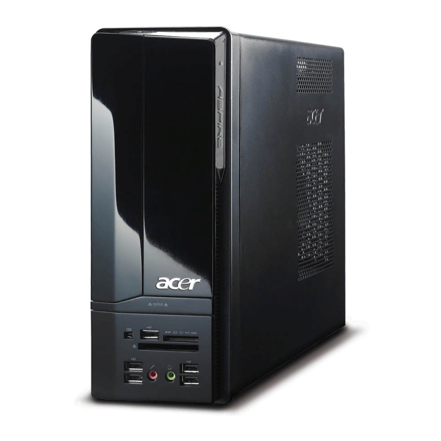
System Components This section includes a virtual tour of the X1700 and Veriton X270 systems’ interior and exterior components. Front Panel X1700 model Icon Chapter 1 Component X1700 model: HDD activity indicator X270 model: Optical drive X1700 model: Optical drive bay door X270 model: Optical drive activity indicator Drive bay door eject button Press to open drive bay door and access the optical drive. -
Page 12: Rear Panel
Rear Panel X1700 model Icon Component Expansion slot (Photo shows graphics card and TV tuner card) Line-out jack Microphone/speaker-out/line-in jack S/PDIF port USB 2.0 ports eSATA port VGA monitor port HDMI port PS2 keyboard port Voltage selector switch Power connector PS2 mouse port Serial port Gigabit LAN port (10/100/1000 Mbps) -
Page 13: Internal Components
Internal Components X1700 model Component HDD drive Optical drive X1700 model: Expansion cards X270 model: N/A Mainboard Heat sink fan assembly Power supply Chapter 1 X270 model... -
Page 14: System Led Indicators
System LED Indicators This section describes the different system LED indicators. LED indicator Color Power Green Green — HDD activity Green Green Green/ Amber Amber LAN activity Green (X270 — model) Green LAN port Amber network speed Green LED (left) —... -
Page 15: System Utilities
System Utilities CMOS Setup Utility CMOS setup is a hardware configuration program built into the system ROM, called the complementary metal- oxide semiconductor (CMOS) Setup Utility. Since most systems are already properly configured and optimized, there is no need to run this utility. You will need to run this utility under the following conditions. When changing the system configuration settings ... -
Page 16: Entering Cmos Setup
Entering CMOS setup Turn on the computer and the monitor. If the server is already turned on, close all open applications, then restart the server. During POST, press Delete. If you fail to press Delete before POST is completed, you will need to restart the server. The Setup Main menu will be displayed showing the Setup’s menu bar. -
Page 17: Setup Utility Menus
Setup Utility Menus The Setup Main menu includes the following main setup categories. Product Information Standard CMOS Features Advanced BIOS Features Advanced Chipset Features Integrated Peripherals Power Management Setup PC Health Status Frequency/Voltage Control ... -
Page 18: Product Information
Product Information The Product Information menu displays basic information about the system. These entries are for your reference only and are not user-configurable. Parameter Description Processor Type Type of CPU installed on the system. Processor Speed Speed of the CPU installed on the system. System Memory Total size of system memory installed on the system. -
Page 19: Standard Cmos Features
Standard CMOS Features Parameter Description System Date Set the date following the weekday-month-day-year format. System Time Set the system time following the hour-minute-second format. SATA Port 1/2/3 Press Enter to view detailed device information connected to the SATA connectors. Halt On Determines whether the system will stop for an error during the POST. -
Page 20: Advanced Bios Features
Advanced BIOS Features Parameter Description Reset Configuration Data Allows you to manually force BIOS to clear the previously saved Extended System Configuration Data (ESCD) data and reconfigure the settings. When set to no, it lets the BIOS configure all the devices in the system. When set to yes, it lets the OS configure Plug and Play (PnP) devices not required for boot if the system has a PnP OS. -
Page 21: Advanced Chipset Features
Advanced Chipset Features Parameter Description Intel EIST When enabled, this feature allows the OS to reduce power consumption. When disabled, the system operates at maximum CPU speed. Intel XD Bit When enabled, the processor disables code execution when a worm attempts to insert a code in the buffer preventing damage and worm propagation. -
Page 22: Integrated Peripherals
Integrated Peripherals Parameter Description Onboard SATA Controller Enables or disables the onboard SATA controller. Onboard SATA Mode Select an operating mode for the onboard SATA. Legacy USB Support Enables or disables support for legacy USB devices. Onboard Graphics Enables or disables the onboard graphics controller. Controller Onboard Audio Controller Enables or disables the onboard audio controller. -
Page 23: Power Management Setup
Power Management Setup Parameter Description ACPI Aware O/S Enables or disables the Advanced Configuration and Power Management (ACPI) function. ACPI Suspend Mode Select an ACPI state. Power On by PCIE Devices Enables or disables to wake up the system from a power saving mode through an event on PCI Express device. -
Page 24: Pc Health Status
PC Health Status Parameter Description Smart FAN Enables or disables the smart system fan control function. Option Enabled Disabled Chapter 2... -
Page 25: Frequency/Voltage Control
Frequency/Voltage Control Parameter Description Spread Spectrum Enables or disables the reduction of the mainboard’s EMI. Note: Remember to disable the Spread Spectrum feature if you are overclocking. A slight jitter can introduce a temporary boost in clock speed causing the overclocked processor to lock up. Chapter 2 Option Enabled... -
Page 26: Bios Security Features
BIOS Security Features Parameter Description Supervisor Password Indicates the status of the supervisor password. User Password Indicates the status of the user password. Change Supervisor Supervisor password prevents unauthorized access to the BIOS Setup Utility. Password Press Enter to change the Supervisor password. Setting a supervisor password Use the up/down arrow keys to select Change Supervisor Password menu then press Enter. -
Page 27: Load Default Settings
Load Default Settings The Load Default Settings menu allows you to load the default settings for all BIOS setup parameters. Setup defaults are quite demanding in terms of resources consumption. If you are using low-speed memory chips or other kinds of low-performance components and you choose to load these settings, the system might not function properly. -
Page 28: Save And Exit Setup
Save & Exit Setup The Save & Exit Setup menu allows you to save changes made and close the Setup Utility. Chapter 2... -
Page 29: Exit Without Saving
Exit Without Saving The Exit Without Saving menu allows you to discard changes made and close the Setup Utility. Chapter 2... - Page 30 Chapter 2...
-
Page 31: System Disassembly
System Disassembly This chapter contains step-by-step procedures on how to disassemble the Aspire X1700 or Veriton X270 desktop computer for maintenance and troubleshooting. Disassembly Requirements To disassemble the computer, you need the following tools: Wrist grounding strap and conductive mat for preventing electrostatic discharge ... -
Page 32: Pre-Disassembly Procedure
Pre-disassembly Procedure Before proceeding with the disassembly procedure, perform the steps listed below: Turn off the system and all the peripherals connected to it. Unplug the power cord from the power outlets. Unplug the power cord from the system. Unplug all peripheral cables from the system. Place the system unit on a flat, stable surface. -
Page 33: Main Unit Disassembly
Main Unit Disassembly X1700 model OPTICAL DISK DRIVE HDD-ODD BRACKET POWER SUPPLY MEMORY MODULES CARD READER BOARD POWER SWITCH AND LED CABLE BRACKET Chapter 3 MAIN UNIT DISASSEMBLY MAIN UNIT SIDE PANEL FRONT BEZEL HEAT SINK FAN ASSEMBLY Ax3, Cx1 VGA CARD TV TUNER CARD FRONT I/O BOARD... -
Page 34: X270 Model
X270 model HEAT SINK FAN OPTICAL DISK DRIVE HDD-ODD BRACKET POWER SUPPLY MEMORY MODULES CARD READER BOARD POWER SWITCH AND LED CABLE BRACKET LAN ACTIVITY AND HDD LED CABLE BRACKET MAIN UNIT DISASSEMBLY MAIN UNIT SIDE PANEL FRONT BEZEL ASSEMBLY Ax3, Cx1 FRONT I/O BOARD FRONT I/O AND... -
Page 35: Screw List
Screw List Chapter 3 Screw #6-32 L5 BZN M3xL5 BZN #6-32 L6 NI #6-32*3/16 NI #6-32 5MM NI Part No. 86.00J07.B60 86.1A324.5R0 86.00J44.C60 86.5A5B6.012 86.9A5G6.162... -
Page 36: Removing The Side Panel
Removing the Side Panel Perform the pre-disassembly procedure described on page 24. Remove the two screws (A) located on the side panel. X1700 model Screw (Quantity) #6-32 L5 BZN (2) Slide the side panel toward the back of the chassis until the tabs on the cover disengage with the slots on the chassis. -
Page 37: Removing The Front Bezel
Removing the Front Bezel Remove the side panel. Refer to the previous section for instructions. Release the front bezel retention tabs from the chassis interior. X1700 model Pull the bezel away from the chassis. X1700 model Chapter 3 X270 model X270 model... -
Page 38: Removing The Heat Sink Fan Assembly
Removing the Heat Sink Fan Assembly WARNING:The heat sink becomes very hot when the system is on. NEVER touch the heat sink with any metal or with your hands. See “Removing the Side Panel” on page 28. See “Removing the Front Bezel” on page 29. Use a long-nosed screwdriver to loosen the four screws on the heat sink, in the order as shown below. - Page 39 Lay down the heat sink fan assembly, in an upright position, on top of the optical drive, as shown below, then disconnect the fan cable from the mainboard. X1700 model Remove the heat sink fan assembly from the chassis then lay it down in an upright position—with the thermal patch facing upward.
-
Page 40: Removing The Processor
Removing the Processor IMPORTANT:Before removing a processor from the mainboard, make sure to create a backup file of all important data. WARNING:The processor becomes very hot when the system is on. Allow it to cool off first before handling. See “Removing the Side Panel” on page 28. See “Removing the Front Bezel”... - Page 41 Pull out the processor from the socket. IMPORTANT:If you are going to install a new processor, note the arrow on the corner to make sure the processor is properly oriented over the socket. Chapter 3...
-
Page 42: Removing The Optical Drive
Removing the Optical Drive This section includes instructions on how to remove the X1700 and X270 computers’ optical drive. To remove the X1700 computer’s optical drive: See “Removing the Side Panel” on page 28. See “Removing the Front Bezel” on page 29. See “Removing the Heat Sink Fan Assembly”... - Page 43 Pull the drive out of the drive bay. To remove the X270 computer’s optical drive: See “Removing the Side Panel” on page 28. See “Removing the Front Bezel” on page 29. See “Removing the Heat Sink Fan Assembly” on page 30. See “Removing the Processor”...
- Page 44 Release the drive bay retention release lever (1) and pull the lever to the fully open position (2). Pull the drive out of the drive bay. Chapter 3...
-
Page 45: Removing The Hard Disk Drive
Removing the Hard Disk Drive See “Removing the Side Panel” on page 28. See “Removing the Front Bezel” on page 29. See “Removing the Heat Sink Fan Assembly” on page 30. See “Removing the Processor” on page 32. See “Removing the Optical Drive” on page 34. Remove the HDD-ODD bracket. - Page 46 Disconnect the data and power cables from the rear of the hard drive. X1700 model Disconnect the other end of the data cable from the mainboard. Place the bracket on a clean, static-free work surface. X270 model Chapter 3...
- Page 47 10. Remove the HDD module. Remove the four screws (D) that secure the HDD module to the HDD bracket. X1700 model Screw (Quantity) #6-32*3/16 NI (4) Slide the HDD out of the bracket. X1700 model Chapter 3 Color Torque Silver 5.5 to 6.5 kgf-cm X270 model Part No.
-
Page 48: Removing The Power Supply
Removing the Power Supply See “Removing the Side Panel” on page 28. See “Removing the Front Bezel” on page 29. See “Removing the Heat Sink Fan Assembly” on page 30. See “Removing the Processor” on page 32. See “Removing the Optical Drive” on page 34. See “Removing the Hard Disk Drive”... - Page 49 Remove the three screws (A) that secure the power supply to the rear panel. Screw (Quantity) Color Torque Part No. #6-32 L5 BZN (3) Black 5.5 to 6.5 kgf-cm 86.00J07.B60 10. Lift the power supply module out of the chassis. X1700 model X270 model Chapter 3...
-
Page 50: Removing The Memory Modules
Removing the Memory Modules IMPORTANT:Before removing any DIMM from the memory board, make sure to create a backup file of all important data. See “Removing the Side Panel” on page 28. See “Removing the Front Bezel” on page 29. See “Removing the Heat Sink Fan Assembly” on page 30. See “Removing the Processor”... -
Page 51: Removing The Vga Card (X1700 Model)
Removing the VGA Card (X1700 model) See “Removing the Side Panel” on page 28. See “Removing the Front Bezel” on page 29. See “Removing the Heat Sink Fan Assembly” on page 30. See “Removing the Processor” on page 32. See “Removing the Optical Drive” on page 34. See “Removing the Hard Disk Drive”... -
Page 52: Removing The Tv Tuner Card (X1700 Model)
Removing the TV Tuner Card (X1700 model) See “Removing the Side Panel” on page 28. See “Removing the Front Bezel” on page 29. See “Removing the Heat Sink Fan Assembly” on page 30. See “Removing the Processor” on page 32. See “Removing the Optical Drive”... -
Page 53: Removing The Front I/O And Card Reader Boards
Removing the Front I/O and Card Reader Boards See “Removing the Side Panel” on page 28. See “Removing the Front Bezel” on page 29. See “Removing the Heat Sink Fan Assembly” on page 30. See “Removing the Processor” on page 32. See “Removing the Optical Drive”... - Page 54 10. Disconnect the other end of the USB, 1394, and audio cables from the mainboard. 11. Remove the front I/O and card reader board bracket. Remove the two screws (D) that secure the bracket to the chassis. X1700 model X270 model Screw (Quantity) Color Torque...
- Page 55 Push the bracket into the chassis then remove the bracket. X1700 model 12. Remove the card reader board. Remove the two screws (C) that secure the card reader board to the bracket. Screw (Quantity) #6-32 L6 BZN (2) Pull the card reader board out of the bracket. Chapter 3 Color Torque...
- Page 56 13. Remove the front I/O board. Remove the two screws (C) that secure the I/O board to the bracket. Screw (Quantity) #6-32 L6 BZN (2) Pull the I/O board out of the bracket. Color Torque Silver 3.5 to 4.5 kgf-cm Part No.
-
Page 57: Removing The Mainboard
Removing the Mainboard See “Removing the Side Panel” on page 28. See “Removing the Front Bezel” on page 29. See “Removing the Heat Sink Fan Assembly” on page 30. See “Removing the Processor” on page 32. See “Removing the Optical Drive” on page 34. See “Removing the Hard Disk Drive”... - Page 58 13. Remove the six screws (C) that secure the mainboard to the chassis. X1700 model Screw (Quantity) #6-32 L5 BZN (6) 14. Lift the board from the chassis. X1700 model Color Torque Silver 5.7 to 6.3 kgf-cm X270 model Part No. 86.00J44.C60 X270 model Chapter 3...
-
Page 59: Removing The Power Switch And Led Cables
Removing the Power Switch and LED Cables See “Removing the Side Panel” on page 28. See “Removing the Front Bezel” on page 29. See “Removing the Heat Sink Fan Assembly” on page 30. See “Removing the Processor” on page 32. See “Removing the Optical Drive”... - Page 60 13. Pull the LED bracket up and lift up from the chassis. 14. Release the two locking tabs (1) and gently pull the power LED cable out (2). Chapter 3...
- Page 61 15. Remove the power switch cable. Release the two locking tabs (1), pull power switch cable bracket out of the LED bracket (2). Grasp the power switch cable bracket and pull the power switch cable out of the bracket. 16. Release the two locking tabs (1) and gently pull the power LED cable out (2). Chapter 3...
-
Page 62: Removing The Lan Activity And Hdd Led Cables (X270 Model)
Removing the LAN Activity and HDD LED Cables (X270 model) See “Removing the Side Panel” on page 28. See “Removing the Front Bezel” on page 29. See “Removing the Heat Sink Fan Assembly” on page 30. See “Removing the Processor” on page 32. See “Removing the Optical Drive”... -
Page 63: System Troubleshooting
This chapter provides instructions on how to troubleshoot system hardware problems. Hardware Diagnostic Procedure IMPORTANT:The diagnostic tests described in this chapter are only intended to test Acer products. Non-Acer products, prototype cards, or modified options can give false errors and invalid system responses. -
Page 64: System Check Procedures
Verify that components are properly seated. Verify that all cable connectors inside the system are firmly and correctly attached to their appropriate connectors. Verify that all components are Acer-qualified and supported. 10. Replace the system covers. 11. Power on the system. -
Page 65: Beep Codes
Beep Codes Beep codes are used by the BIOS to indicate a serious or fatal error to the end user. Beep codes are used when an error occurs before the system video has been initialized. Beep codes will be generated by the system board speaker, commonly referred to as the PC speaker. -
Page 66: Online Support Information
This section describes online technical support services available to help you repair the desktop computer. If you are a distributor, dealer, ASP or TPM, please refer your technical queries to your local Acer branch office. Acer Branch Offices and Regional Business Units may access our website at http://global.acer.com/ support/index. -
Page 67: System Block Diagram And Board Layout
System Block Diagram and Board Layout System Block Diagram VREG CONN HDMI HDMI CONN DVI CONN PCIE16X SLOT PCI-E 1x Slot 1 PCI Slot 1,2 1394 Conn. 1394 VT6308P 8M FLASH ROM ALC 888/888S AUDIO CODEC CONTOLLER RJ45 RTL8111B&8101E&8111C Chapter 5 BLOCK DIAGRAM LGA775 (VRM11) -
Page 68: Board Layout
Board Layout Mainboard Chapter 5... - Page 69 Code Description PWR2 24-pin ATX power connector CLR_CMOS1 Clear CMOS jumper F_USB2 Front USB connector PANEL1 LED cable connector F_USB3 Front USB connector SATA1 and 2 SATA data cable connectors F_USB1 Front USB connector PCIE16x PCI Express x16 slot 13941 1394 connector F_AUDIO1 Front audio connector...
-
Page 70: System Jumpers
System Jumpers Name General Purpose Input/Output Clear CMOS Location Default GPIO32 GPIO33 CLR_CMOS1 Settings Short Open Normal (default) Clear CMOS Chapter 5... -
Page 71: Fru (Field Replaceable Unit) List
To scrap or to return the defective parts, follow the local government ordinance or regulations on how to dispose it properly, or follow the rules set by your regional Acer office on how to return it. This document will be updated as more information about the FRU list becomes available. -
Page 72: Exploded Diagram
33.3V002.001 FRONT IO BKT 60.3V808.001 ASSY FRONT BEZEL 42.3V811.001 BEZEL PROTECTFILM 42.3V809.001 ODD KNOB PROTECTFILM 42.3V805.001 ODD DOOR 34.3V005.001 acer LOGO 42.3V806.001 FRONT BEZEL COVER 42.3V808.001 BEZEL COVER PROTECTFILM 42.3V810.001 ODD DOOR PROTECTFILM 42.3V814.001 DOOR ARM 34.3V004.001 ODD DOOR SPRING 42.3V807.001... -
Page 73: X270
SCREW #6-32 L5 PAN NI 60.3V411.001 ASSY BKT-UCASE 34.3V002.001 PCI SHIELDING 34.3V001.001 REAR IO SHIELDING 60.3V404.001 ASSY LCASE-ASM RUBBER 80X10X5.5 47.3V002.001 33.3V002.001 FRONT IO BKT 42.3V404.001 LENS 41.3V401.201 FRONT BEZEL 42.3V403.001 BELT 31.3V401.001 ACER LOGO 42.3V402.001 POWER BUTTON 60.3V408.001 ASSY ODD-HDD-ASM... -
Page 74: X1700 Fru List (81.3V401.007G)
EDITION RC PHILLIPS VISTA MCE-SC EDITION RC PHILIPS VISTA EMEA RT.11300 DA078L/BOXER FRONT I/O BD DA078L/BOXER CARD READER BOXER61 CARD READER WO 1394 -1 MODEM 56K ATX LSI UNIVERSAL Acer Description Part Number RV.11000.003 RV.11000.004 RV.11000.007 RV.11000.010 RT.11300.001 RT.11300.002 RT.11300.003 RT.11300.004... - Page 75 POWER CORD 1800MM 250V EURO C.A. LED-SWITCH BOXER VSO ASSY MAIN-CHASSIS BOXER2 ASSY LCASE-ASM BOXER2 ASSY BRKT-ODD-HDD BOXER2 ASSY BRKT-UCASE BOXER PUG ASSY FRONT-BEZEL-ASM BOXER2 BRKT L/P DUMMY LY Acer Description Part Number TU.10500.010 TU.10500.011 NI.10200.009 NI.10200.002 VG.PC93G.EA2 VG.APC34.5A2 50.SAR01.002 50.SBF01.001...
- Page 76 IC CPU KENTSFIELD Q6700 2.66G IC CPU YORKFIELD Q8200 2.33G IC CPU YORKFIELD Q9300 2.5G IC CPU YORKFIELD Q9400 2.66G IC CPU YORKFIELD Q9450 2.66G IC CPU YORKFIELD Q9550 2.83G IC CPU YORKFIELD Q9650 3.0G Acer Description Part Number 60.SBF01.005 KC.D0001.450 KC.12001.CDE KC.22001.DEM KC.22201.DEM...
- Page 77 HDD 320GB HGST HDP725032GLA380 HDD SEAGATE 320GB ST3320813AS HDD 500GB HGST HDP725050GLA380 HDD 500GB WD5000AAJS-22A8B0 HDD 500GB SEAGAT ST3500820AS HDD 640GB WD WD6400AAKS- 22A7B0 ASSY COOLER LGA775 ATX Acer Description Part Number KU.0160D.043 KU.0160E.015 KU.0160F.005 KV.01609.003 KV.0160D.014 KH.16008.023 KH.16001.031 KH.16007.017 KH.32008.014 KH.32007.003...
- Page 78 KB PS2 KB-0759 BRAZILIAN PORTU KB PS2 KB-0759 JAPANESE BLACK KB PS2 KB-0759 GERMAN BLACK KB PS2 KB-0759 ITALIAN BLACK 1 KB PS2 KB-0759 SWEDISH BLACK KB PS2 KB-0759 UK BLACK 105KS Acer Description Part Number KB.PS203.109 KB.PS203.121 KB.PS203.096 KB.PS203.097 KB.PS203.098 KB.PS203.099...
- Page 79 KB PS2 KB-0759 CZECH BLACK KB PS2 KB-0759 ROMANIAN BLACK KB PS2 KB-0759 TURKISH BLACK KB PS2 KB-0759 SPANISH LATIN KB PS2 KB-0759 TURKISH-Q BLACK KEYBOARD CHICONY KU-0760 USB S Acer Description Part Number KB.PS203.112 KB.PS203.113 KB.PS203.114 KB.PS203.115 KB.PS203.116 KB.PS203.117 KB.PS203.118...
- Page 80 KB USB KU-0760 ITALIAN BLACK 1 KB USB KU-0760 FRENCH BLACK KB USB KU-0760 SWEDISH BLACK KB USB KU-0760 UK BLACK 105KS KB USB KU-0760 DUTCH BLACK KB USB KU-0760 SWISS/G BLACK KB USB KU-0760 BELGIUM BLACK Acer Description Part Number KB.USB03.063 KB.USB03.064 KB.USB03.065 KB.USB03.066 KB.USB03.067...
- Page 81 KB USB KU-0760 ROMANIAN BLACK KB USB KU-0760 TURKISH BLACK KB USB KU-0760 SPANISH LATIN B KB USB KU-0760 SPANISH LATIN B KB USB KU-0760 TURKISH-Q BLACK KB WL KG-07663US2552V US 104K Acer Description Part Number KB.USB03.081 KB.USB03.082 KB.USB03.083 KB.USB03.084 KB.USB03.085 KB.USB03.086...
- Page 82 MOUSE USB OPT SM-9625 LITEON MOUSE WL MG-0766T-657 CHICONY SPS 220W PFC 230V LITEON PE- SPS 220W PFC 230V DPS-220UB- SPS 220W 115VAC/230V NPFC DPS- SPS 220W NPFC 115V/230V LITEON Acer Description Part Number MB.SB801.002 KN.1GB0H.009 KN.1GB03.024 KN.1GB0F.002 KN.1GB01.018 KN.2GB03.009 KN.2GB01.013...
- Page 83 SCRW PAN #6-32 L6 NI BOXER SCRW PAN M3 L5 BZN SCREW FLAT #6-32*3/16 NI SCRW MB FLAT #6-32 5MM NI Speaker SPEAKER CHIAMAW 9M-20A200- 000 ACER LOGO LF 0810 SPEAKER USB2.0 DXP 1007011- SPEAKER JAZZ USB2.0 USB MS1238UA Chapter 6 Part Name...
-
Page 84: X270 Fru List (91.3V401.006G)
RC PHILIPS VISTA EMEA RT.11300 PHILIPS VISTA MCE TRANSCEIVER RC receiver+IR blaster RXX6000 PHILIPS VISTA MCE RECEIVER RECEIVER RF DANGLE RG-0618U- DA078L/BOXER FRONT I/O BD DA078L/BOXER CARD READER MODEM 56K ATX LSI UNIVERSAL Acer Description Part Number RT.11300.001 RT.11300.002 RT.11300.003 RT.11300.004 RT.11300.005 RT.11300.006 RT.11300.007... - Page 85 C.A. SATA HDD BOXER VSO C.A. HDD-SATA BOXER95 C.A. SATA ODD PUG BRKT F-IO PUG BRKT L/P DUMMY LY ASSY MAIN-CHASSIS PUG C.A. LED SWITCH PUG ASSY BRKT-UCASE BOXER PUG ASSY LCASE-ASM BOXER2 Acer Description Part Number NI.10200.002 NI.10200.009 TU.10500.010 TU.10500.011 VG.APC34.5A2 VG.PC93G.A04 VG.PC93G.EA2...
- Page 86 IC CPU YORKFIELD Q8200 2.33G IC CPU WOLFDALE E8400 3.0G IC CPU YORKFIELD Q9300 2.5G IC CPU YORKFIELD Q9400 2.66G IC CPU YORKFIELD Q9450 2.66G IC CPU YORKFIELD Q9550 2.83G IC CPU YORKFIELD Q9650 3.0G Acer Description Part Number 60.3V408.001 41.3V401.201 KC.22201.DEM KC.12001.CDE KC.21801.DEM...
- Page 87 ST3320813AS HDD 500GB HGST HDP725050GLA380 HDD 500GB WD5000AAJS-22A8B0 HDD 500GB SEAGAT ST3500820AS HDD 640GB WD WD6400AAKS- 22A7B0 ASSY COOLER LGA775 ATX FAN COOLER LGA775 TMDC6 NEW SP Acer Description Part Number KC.D0001.450 KU.0160D.043 KU.0160E.015 KU.0160F.005 KV.01609.003 KV.0160D.014 KH.16008.023 KH.16001.031 KH.16007.017 KH.32008.014...
- Page 88 KB PS2 KB-0759 JAPANESE BLACK KB PS2 KB-0759 GERMAN BLACK KB PS2 KB-0759 ITALIAN BLACK 1 KB PS2 KB-0759 SWEDISH BLACK KB PS2 KB-0759 UK BLACK 105KS KB PS2 KB-0759 DUTCH BLACK Acer Description Part Number KB.USB03.062 KB.PS203.096 KB.PS203.097 KB.PS203.098 KB.PS203.099...
- Page 89 KB PS2 KB-0759 CZECH BLACK KB PS2 KB-0759 ROMANIAN BLACK KB PS2 KB-0759 TURKISH BLACK KB PS2 KB-0759 SPANISH LATIN KB PS2 KB-0759 TURKISH-Q BLACK KB WL KG-07663US2552V US 104K Acer Description Part Number KB.PS203.113 KB.PS203.114 KB.PS203.115 KB.PS203.116 KB.PS203.117 KB.PS203.118 KB.PS203.119...
- Page 90 KB USB KU-0760 ITALIAN BLACK 1 KB USB KU-0760 FRENCH BLACK KB USB KU-0760 SWEDISH BLACK KB USB KU-0760 UK BLACK 105KS KB USB KU-0760 DUTCH BLACK KB USB KU-0760 SWISS/G BLACK KB USB KU-0760 BELGIUM BLACK Acer Description Part Number KB.USB03.063 KB.USB03.064 KB.USB03.065 KB.USB03.066 KB.USB03.067...
- Page 91 KB USB KU-0760 ROMANIAN BLACK KB USB KU-0760 TURKISH BLACK KB USB KU-0760 SPANISH LATIN B KB USB KU-0760 SPANISH LATIN B KB USB KU-0760 TURKISH-Q BLACK ENMCP73PV NVIDIA MCP73PV W/ Acer Description Part Number KB.USB03.081 KB.USB03.082 KB.USB03.083 KB.USB03.084 KB.USB03.085 KB.USB03.086...
- Page 92 LITEON SCRW I NO6-32 L5 BZN SCRW PAN #6-32 L6 NI BOXER SCRW #6-32 L5 PAN NI SCRW PAN M3 L5 BZN SCREW FLAT #6-32*3/16 NI SCRW MB FLAT #6-32 5MM NI Acer Description Part Number KN.1GB0H.009 KN.1GB03.024 KN.1GB0F.002 KN.1GB01.018 KN.2GB03.009...
- Page 93 Component Speaker SPEAKER CHIAMAW 9M-20A200- 000 ACER LOGO LF 0810 SPEAKER USB2.0 DXP 1007011- SPEAKER JAZZ USB2.0 USB MS1238UA Part Name SPEAKER ACER LOGO/LF0810 USB/0810 AC.203USB.0G ACER SPEAKER JS USB2.0 USB MS1238UA Acer Description Part Number SP.10600.011 SP.10600.010 SP.10600.013 Chapter 6...
-
Page 94: Technical Specifications
Technical Specifications This section provides technical specifications for the X1700 and X270 system. Processor Intel Core 2 Quad Item Specification Model Number Q6600 Core (nm) L2 Cache Size (MB) Clock Speed (GHz) Front Side Bus (MHz) 1066 Frequency (MHz) 2400 Socket Clock Multiplier Voltage (V) - Page 95 Intel Pentium Dual-Core Item Specification Model Number E2180 Architecture (nm) L2 Cache Size (MB) Clock Speed (GHz) Front Side Bus (MHz) 800 Frequency (MHz) 2000 Socket LGA 775 Clock Multiplier Voltage (V) 1.162-1.312 Thermal Design Power (W) Intel Celeron Dual-Core Item Specification Type...
-
Page 96: System Board Major Chips
System Board Major Chips Item Specification System core logic NVIDIA NForce MCP73PV 1048 BGA Memory controller NVIDIA NForce MCP73PV 1048 BGA Storage controller NVIDIA NForce MCP73PV 1048 BGA Video controller NVIDIA NForce MCP73PV 1048 BGA PCI controller NVIDIA NForce MCP73PV 1048 BGA LAN controller NVIDIA NForce MCP73PV 1048 BGA + Realtek RTL8211C Audio controller... -
Page 97: Hard Disk Drive
Hard Disk Drive Item Specification Storage controller NVIDIA NForce MCP73PV 1048 BGA Vendor Model no. WD1600AAJS-22WAA0 WD3200AAJS-22B4A0 WD5000AAJS-22A8B0 WD6400AAKS-22A7B0 Interface SATA Size 3.5-inch Transfer rate (Gb/s) Spindle speed (RPM) 7200 Capacity (GB) 160, 320, 500, 640 Cache (MB) 160/320/500 GB: 8 640 GB: 16 PCI Interface Item... -
Page 98: Optical Drive
Optical Drive Super Multi Item Vendor Model name Drive type Write Speed Read Speed Data Transfer Rate Access Time Buffer Size Interface Type DVD-ROM Item Vendor Model name Drive type Write Speed Read Speed Data Transfer Rate Access Time Buffer Size Interface Type Specification HLDS... - Page 99 Appendix A...
Need help?
Do you have a question about the ASPIRE ASPIRE X1700 and is the answer not in the manual?
Questions and answers
How do you? Hook it up to the TV and have it hooked up right?But I can't make it play.What channel do I need it on