Table of Contents
Advertisement
Electronic
Instruction manual
Theodolites
2 sec. Angle Accuracy
ETH-302
Detachable Tribrach
5 sec. Angle Accuracy
ETH-305
Detachable Tribrach
ETH-310
10 sec. Angle Accuracy
Detachable Tribrach
20 sec. Angle Accuracy
ETH-320
Detachable Tribrach
2-5-2 Higashi-Oizumi / Nerima-ku, Tokyo 178-0063, Japan
PENTAX Industrial Instruments Co., Ltd.
Tel. +81-3-5905-1222 / Fax +81-3-5905-1225
E-mail:
international@piic.pentax.co.jp
Total Construction Solutions
Advertisement
Table of Contents

Related Manuals for Pentax ETH-302


Summary of Contents for Pentax ETH-302
- Page 1 5 sec. Angle Accuracy ETH-305 Detachable Tribrach ETH-310 10 sec. Angle Accuracy Detachable Tribrach 20 sec. Angle Accuracy ETH-320 Detachable Tribrach 2-5-2 Higashi-Oizumi / Nerima-ku, Tokyo 178-0063, Japan Total Construction Solutions PENTAX Industrial Instruments Co., Ltd. Tel. +81-3-5905-1222 / Fax +81-3-5905-1225 E-mail: international@piic.pentax.co.jp...
-
Page 3: Safety Precautions
Safety Precautions The following items are intended to prevent possible injury to the user or other people and/or damage to the instrument before it occurs. These safety precautions are important to the safe operation of this product and should be observed at all times. •... - Page 4 CAUTION • Secure the handle of main unit with the handle locking screws. Failure to properly secure the handle could result in the main unit detaching from the handle while being carried, causing injury. • Do not use the carrying case as a footstool as it is slippery and unstable and may cause you to fall, resulting in possible injury.
-
Page 5: Table Of Contents
CONTENTS • 1. General Precautions Standard equipment Names of Parts Preparation of power • 2. Key Operations and Display Display Keyboard Function of each key 2.3.1 Power on-off key 2.3.2 V/% key 2.3.3 Hold key 2.3.4 0 set key 2.3.5 R/L key 2.3.6 Illumination key Other functions 2.4.1 Remaining battery indicator... - Page 6 CONTENTS • 5. Measurement Horizontal angle measurement (right) Horizontal angle measurement (left) Vertical angle measurement • 6. Inspection and Adjustment Instructions on inspection and adjustment Perpendicularity of plate vial to vertical axis Perpendicularity of circular vial to vertical axis Inclination of reticule graduations Perpendicularity of line of sight to horizontal axis Difference of the vertical angle Optical plummet...
-
Page 7: General
1. General 1.1 Precautions Storing and environmental conditions • Do not use the instrument until it has adjusted to the ambient temperature. • Avoid using at a high or low temperature. The instrument may not work normally at temperatures exceeding –10 or +50˚C. •... - Page 8 Transportation • Do not subject to impact or vibration during transportation. • When transporting, handle the same as ”fragile” and pack the shipping case with cushioning materials. Inspection, Adjustment and Repair, Overhaul • When not in use for extended periods of having been subjected to impact or vibration, be sure to check the instrument adjustments before using.
-
Page 9: Standard Equipment
Others • When cleaning the case or the instrument, do not use any organic solvent. The surface of plastic parts may dissolve and deformation and discoloration can occur. Wipe off the dirt with a wet cloth of dilute household detergent •... - Page 10 Unpacking and Storing Unpacking • Gently set down the carrying case so that its cover is upward. • Unlatch and open the case while pushing the latch lock. • Take the instrument out of the case. Storing • Set the telescope almost horizontal, and lightly tighten the telescope clamp screw.
-
Page 11: Names Of Parts
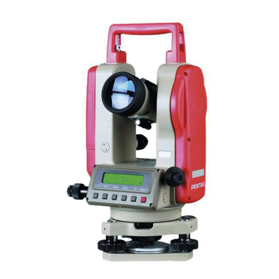
1.3 Names of Parts Handle Screw for handle Collimator Objective lens Instrument height mark (215mm) Optical plummet Leveling screw Bottom plate Tribrach locking lever... - Page 12 Eyepiece cap Eyepiece lens Focusing knob Plate vial LCD panel Keyboard Battery box Telescope tangent screw Telescope clamp screw Horizontal clamp screw Horizontal tangent screw Circular vial...
-
Page 13: Preparation Of Power
• Press the battery box to the leg by inserting the guide pin to the guide groove. • Confirm the correct work by pressing the power switch. This instrument can operate using 1.2V AA rechargeable batteries. • The four (4) batteries, in a battery box, should be of the same type. -
Page 14: Key Operations And Display
2. Key Operations and Display 2.1 Display Vertical angle V=Zenith 0°, V%=Slope(VH=Horizontal 0°, Vc=Compass) Horizontal angle Battery indicator: (HR=right rotation horizontal angle, HL=left rotation horizontal angle) 2.2 Keyboard [V/%] key (Switches the display of vertical angle) [R/L] key (Set the horizontal angle right and left rotation alternately) [HOLD] key (Pressing twice holds the horizontal... -
Page 15: Function Of Each Key
2.3 Function of each key 2.3.1 Power [ON/OFF] key <Power ON and set the vertical angle 0 point> Pressing the ON/OFF key turns on the power supply and the message ”0 SET” is displayed. After the ”0 SET” of vertical angle is performed, the Horizontal and Vertical angle are displayed and the instrument enters into the angle measurement mode. -
Page 16: V/% Key
2.3.2 [V/%] key Pressing the V/% key will change the Vertical angle display to V%(slope). (At the shipping, it is set at Zenith 0°) By special key operation, horizontal 0° (VH) and Compass (Vc) can be set. (Factory default is Zenith 0°) (Refer to 3.1 Setting of vertical angle.) - Page 17 The error ”OVER RANGE” is displayed when the telescope exceeds 45°(100%) in the V% display mode.
-
Page 18: Hold Key
2.3.3 [HOLD] key Press the [HOLD] key twice in succession to hold the displayed horizontal angle and retain it. (Press once, the key buzzer will sound, then press again during the sound.) Press the key once more to release. To prevent operation error, the buzzer sounds for three seconds when the [HOLD] key is pressed. -
Page 19: Set Key
2.3.4 [0SET] key Press the [0SET] key twice in succession to reset the displayed horizontal angle 0°,00’ , 00” . (Press once, the key buzzer will sound, then press again during the sound.) Press the key once more to release. To prevent operation error, the buzzer sounds for three seconds when the [OSET] key is pressed. -
Page 20: R/L Key
2.3.5 [R/L] key Press the [R/L] key to change from clockwise to counterclockwise rotation. A clockwise or counterclockwise reading is alternately displayed each time the key is pressed. Clockwise horizontal angle Counterclockwise horizontal angle Count horizontal angle in a left If the power turns off during the counterclockwise mode, the display returns to a clockwise horizontal angle display when power is turned on. -
Page 21: Other Functions
2.4 Other Functions 2.4.1 Remaining battery indicator The status of the remaining battery capacity is displayed with ” ” symbolizing the battery capacity. Battery full - operating possible Operation possible Operation still possible Get the battery ready for a stand by Replace batteries Automatic Power-off function If there is no key operation for about 30 minutes, the power supply is... -
Page 22: Special Key Operations
3. Special key operations Special key operation enables selection of angle unit and other such items. Press [HOLD] key and [0SET] key at the same time Press [ON/OFF] key Release [ON/OFF] key (No display or buzzer) Release [HOLD] key and [0SET] key, Following display appears:... - Page 23 Flow of setting display Setting of vertical angle Press [R/L] key Setting of 90°buzzer Press [R/L] key Setting of correction of vertical angle Press [R/L] key Setting of angle display Press [R/L] key Setting of automatic power off function Press [R/L] key Setting of Angle unit Previous items can be displayed by pressing the [HOLD] key.
-
Page 24: Setting Of Vertical Angle
3.1 Setting of Vertical Angle Vertical angle setting display by special key operation Zenith 0° (V) Setting is switched by pressing [0SET] key Horizontal angle 0°(VH) Compass (Vc) Store with [V/%] key when the setting is decided. -
Page 25: Setting Of 90°Buzzer
3.2 Setting of 90°buzzer 90°buzzer setting display by special key operation No 90°buzzer Setting is switched by pressing [0SET] key With 90°buzzer Store with [V/%] key when the setting decided. 3.3 Setting of correction of vertical angle Correction of vertical angle setting display by special key operation Setting is switched by pressing [0SET] key Store with [V/%] key when the setting decided. -
Page 26: Setting Of Angle Measurement
3.4 Setting of angle measurement Angle setting display by special key operation For models ETH-302/305 Setting is switched by pressing [0SET] key Store with [V/%] key when the setting decided. For models ETH-310 Setting is switched by pressing [0SET] key Store with [V/%] key when the setting decided. -
Page 27: Setting Of Automatic Power-Off Function
3.5 Setting of automatic power off function Automatic power off function setting display by special key operation Automatic power off active Setting is switched by pressing [0SET] key Automatic power off inactive Store with [V/%] key when the setting decided. 3.6 Setting of Angle unit Setting is switched by pressing [0SET] key You can Select DEG or DEC or GRD or MIL as the unit for angle. -
Page 28: Preparation For Surveying
4. Preparation for Surveying 4.1 Setting up the instrument Adjust the tripod legs so that a height suitable for surveying is obtained when the instrument is set on the tripod. A Set the tripod and fix the metal shoe firmly into the ground so that the tripod head is as level as possible and centered above the station point. -
Page 29: Leveling With The Circular Vial
4.2 Leveling with the Circular level After [4.1 Setting up the instrument] is completed, instrument must be leveled using the circular vial. By rotating any two leveling screws, position the bubble in the center of the vial (See A.) (To adjust the screws at the same time, turn them in opposite directions.) Adjust the remaining leveling screw, and position the bubble in the center of the circle (See B) -
Page 30: Leveling With The Plate Vial
4.3 Leveling with the Plate level After [4.2 Leveling with the circular vial] is completed, instrument must be leveled with plate vial. Place the plate vial in parallel with a line joining any two of the leveling screws. By rotating two leveling screws in the opposite direction of each other, position the bubble in the center of the vial (See A) Rotate the plate vial through 90°, position the bubble in the center of the vial by operating the remaining one leveling screw (See B) -
Page 31: Centering With The Optical Plummet
4.4 Centering with the optical plummet After [4.3 Leveling with the plate vials] is completed, the instrument must be centered above the station point. Focus the optical plummet reticule by rotating the optical plummet eyepiece knob. Focus the station point by rotating the optical plummet focusing knob. Loosen the tripod center screw. -
Page 32: Eyepiece Adjustment
4.5 Eyepiece adjustment After [4.4 Centering with the optical plummet] completed, focus the telescope eyepiece on the telescope reticule. Remove the telescope lens cap. Point the telescope at a bright object. Rotate the eyepiece completely counterclockwise. Look through the eyepiece, and rotate the eyepiece clockwise until the reticule appears at its maximum sharpness. -
Page 33: Object Sighting
4.6 Object sighting After [4.5 Eyepiece adjustment] is completed, sight the object. Loosen the telescope clamp screw and horizontal clamp screw. Point the telescope at the object using the collimator sight. Tighten the telescope clamp screw and horizontal clamp screw. Focus on the object by rotating the focusing ring, while looking through the telescope. -
Page 34: Measurement
5. Measurement 5.1 Horizontal angle measurement (right) Level the instrument, and after power on set the vertical angle 0 point. Sight the first object using the horizontal clamp and tangent screw as well as the telescope clamp and tangent screw. Press [0SET] twice to set the horizontal angle to 0°,00’... -
Page 35: Horizontal Angle Measurement (Left)
Subsequent operation will be done as in [5.1 Horizontal angle measurement (right), but the order of collimation is reversed. To switch the mode back to ”right” , press the [R/L] key again. • If the power turns off during the counterclockwise mode, the display returns to a clockwise horizontal angle display when power is turned on. -
Page 36: Vertical Angle Measurement
5.3 Vertical angle measurement Level the instrument, turn the power on and set the vertical angle 0 point. Sight the object A using the horizontal clamp and tangent screws as well as the telescope clamp and tangent screws. Read the displayed value ( ). •... -
Page 37: Inspection And Adjustment
6. Inspection and Adjustment 6.1 Instructions on inspection and adjustment • Inspection and adjustment should be done after setting the instrument on a tripod or on an adjustment stand. • Inspection should be done sequentially from [6.2 Plate vial] to [6.5 Perpendicularity of line of sight to horizontal axis] •... - Page 38 Adjustment Center the plate vial bubble. Rotate the instrument 180°, move the bubble half way back to the center by operating a leveling screw which is located parallel with the plate vial. Rotate the vial adjusting screw with the adjusting pin and position the bubble in the center.
-
Page 39: Perpendicularity Of Circular Vial To Vertical Axis
6.3 Perpendicularity of circular vial to vertical axis Inspection Confirm if the bubble of the circular vial is in the center after the inspection and adjustment of [6.2 Plate vial]. No adjustment is necessary if the bubble of the circular vial is in the center but if not, the following adjustment is required. -
Page 40: Inclination Of Reticule Graduations
6.4 Inclination of reticule graduations Inspection Set an object point A on the line of sight through the telescope. Move point A to the edge of the field of view by adjusting the telescope tangent screw (point A’). No adjustment is necessary if point A moves along the vertical line of the reticule. -
Page 41: Perpendicularity Of Line Of Sight To Horizontal Axis
6.5 Perpendicularity of line of sight to horizontal axis Inspection Set an object (point A) at a distance of 30 to 50m away from the instrument and sight it through the telescope. Loosen the telescope clamp screw and reverse the telescope around the horizontal axis. -
Page 42: Difference Of The Vertical Angle
6.6 Difference of the vertical angle Inspection Set the vertical angle in Zenith 0° mode Sight an object (Point P) with the telescope and read the vertical angle (V correct). Reverse the telescope and rotate the alidade. Sight point P again in the reverse position and read the vertical angle (V reverse). -
Page 43: Optical Plummet
6.7 Optical plummet Inspection Place a piece of white paper, with a cross drawn on it, directly under the instrument. Look through the optical plummet, and move the paper so that the intersecting point of the cross comes to the center of the field of view. Adjust the leveling screws so that the center mark of the optical plummet coincides with the intersection point of the cross. -
Page 44: Optional Accessories
7. Optional Accessories 7.1 Diagonal Eyepiece (SB14) The Diagonal eyepiece can be attached to the telescope for convenience in observing the zenith or when in confined spaces. <Installation> Turn the telescope eyepiece ring counterclockwise to remove the eyepiece. Be sure to hold the eyepiece, securely, so that you do not drop it. Attach the diagonal eyepiece to the telescope by reversing the procedure. -
Page 45: Specifications
Resolving power Field of view Minimum focus distance Stadia ratio Stadia constant Angle Measurement Type Detection mode Minimum Display (Selectable) ETH-302 1”/5” ETH-305 1”/5” ETH-310 5”/10” ETH-320 10”/20” Accuracy (DIN18723, Standard deviation) ETH-302 2” ETH-305 5” ETH-310 10” ETH-320 20”... - Page 46 Vertical axis Single Sensitivity of vials Plate vial ETH-302 ETH-305 ETH-310 ETH-320 Circular vial Tribrach type Detachable Optical plummet Magnification Focusing range Power source Type Operation time (Alkaline) (NiMH2300mAh) 25 to 28 hrs. Water resistant IP x4 Ambient temperature - 10 °C to + 50 °C...
- Page 48 PENTAX Industr PENT X Industrial Instr ial Instrumen 2-5-2 Higashi-Oizumi Nerima-ku, Tokyo 178-0063, Japan PENTAX Industrial Instruments Co., Ltd. Tel.: +81-3-5905-1222 Fax: + 81-3-5905-1225 E-mail: international@piic.pentax.co.jp PENTAX Industrial Instruments C PENTAX Industrial Instrum PENTAX Industrial In PENTAX Industria PENTAX Indust...
Need help?
Do you have a question about the ETH-302 and is the answer not in the manual?
Questions and answers