GE Multilin MM300 Quick Start Manual
Motor management system
Hide thumbs
Also See for Multilin MM300:
- Manual (158 pages) ,
- Instruction manual (198 pages) ,
- Installation recommendations (21 pages)

Related Manuals for GE Multilin MM300


Summary of Contents for GE Multilin MM300
- Page 1 Grid Solutions MM300 Motor Management System Quick Start Guide MM300 Revision: 1.6x Manual P/N: 1601-9022-AC Manual Order Code: GEK-113336L E83849 LISTED IND.CONT. EQ. 52TL *1601-9022-AC*...
- Page 2 The contents of this manual are the property of GE Multilin Inc. This documentation is furnished on license and may not be reproduced in whole or in part without the permission of GE Multilin Inc. The content of this manual is for informational use only and is subject to change without notice.
- Page 3 Warranty For products shipped as of 1 October 2013, GE warrants most of its GE manufactured products for 10 years. For warranty details including any limitations and disclaimers, see our Terms and Conditions at https://www.gegridsolutions.com/multilin/warranty.htm...
-
Page 4: Table Of Contents
TABLE OF CONTENTS Table of Contents OVERVIEW Cautions and Warnings ........................3 Safety words and definitions........................3 General Safety Precautions - MM300.....................3 For Further Assistance.......................... 4 INSTALLATION Mechanical installation ........................1 Dimensions................................1 Product identification .............................2 Mounting ................................2 Electrical installation ..........................6 Module and terminal identification......................7 Full-voltage non-reversing starter ......................8 RS485 connections ............................9... - Page 5 TABLE OF CONTENTS ACTUAL VALUES Actual values overview .........................1 SETPOINTS Understanding setpoints........................1 Configuration setpoints ........................2 Motor setpoints..............................2 Current and voltage transformers......................6 PROTECTION ELEMENTS Thermal protection ..........................1 Overload curve..............................1 COMMUNICATIONS Communications interfaces .......................1 SPECIFICATIONS Protection specifications........................1 User interface specifications......................3 Metering and monitoring specifications..................3 Control specifications ..........................4 Inputs specifications ..........................4...
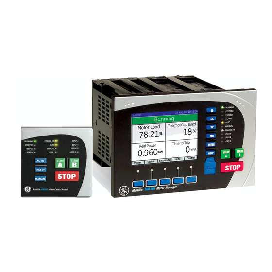
- Page 6 Grid Solutions MM300 Motor Management System Chapter 1: Overview Overview The MM300 is a modular motor protection and control system designed specifically for low-voltage motor applications. The MM300 provides the following key benefits. • Flexible protection, control, and communication options to suit any low-voltage motor application.
- Page 7 CHAPTER 1: OVERVIEW Power Fuse Control PT Control fuse Six inputs and two outputs (standard) Direct voltage inputs Optional (690 V AC maximum) three-phase voltage card METERING Contactor V, A, W, var, VA, PF, Hz Phase CT 3 50G 51G Ambient air Ground CT 1 Stator RTDs...
-
Page 8: Cautions And Warnings
CHAPTER 1: OVERVIEW CAUTIONS AND WARNINGS Cautions and Warnings Before attempting to install or use the device, review all safety indicators in this document to help prevent injury, equipment damage, or downtime. Safety words and definitions The following symbols used in this document indicate the following conditions Indicates a hazardous situation which, if not avoided, will result in death or serious DANGER: injury. -
Page 9: For Further Assistance
Before working on CTs, they must be short-circuited. For Further Assistance For product support, contact the information and call center as follows: GE Grid Solutions 650 Markland Street Markham, Ontario Canada L6C 0M1... -
Page 10: Mechanical Installation
Grid Solutions MM300 Motor Management System Chapter 2: Installation Installation Mechanical installation This section describes the mechanical installation of the MM300 system, including dimensions for mounting and information on module withdrawal and insertion. Dimensions The MM300 is packaged in a modular arrangement. The dimensions of the MM300 are shown below. -
Page 11: Product Identification
MECHANICAL INSTALLATION CHAPTER 2: INSTALLATION Figure 2-1: MM300 dimensions PANEL 6.071” (154,15 mm) 3.746” 4.059” (95,15 mm) (103,09 mm) 0.565” 5.228” (14,35 mm) (132,78 mm) 5.550” (140,97 mm) 853724A1.CDR Product identification The product identification label is located on the side panel of the MM300. This label indicates the product model, serial number, firmware revision, and date of manufacture. - Page 12 CHAPTER 2: INSTALLATION MECHANICAL INSTALLATION Figure 2-3: Base Unit standard panel mounting and cutout dimensions #4 - 40x3/8in SELF-TAP PAN HD PHILIPS QTY: 6 (SUPPLIED); GE PART NO. 1402-0017 TIGHTENING TORQUE: 8 lb-in INSTALL RELAY REAR OF PANEL FROM FRONT...
- Page 13 MECHANICAL INSTALLATION CHAPTER 2: INSTALLATION Figure 2-4: Basic Control Panel mounting and cutout dimensions #4-40X3/8in SELF TAP PAN HD PHILIPS QTY: 8; (SUPPLIED); GE PART# 1402-0017 TIGHTENING TORQUE: 7 lb-in 2.635" 66,93mm 2.515" 63,88mm 1.500" 38,10mm 2.515" 1.500" 2.635" 63,88mm...
- Page 14 [17.06 mm] [58.04 mm] EXPANSION UNIT OUTLINE #6-32 THREADED HOLE 1.500” QTY: 2 [38.10 mm] 853755A1.cdr #6-32X1/2 FT FLAT HEAD PHIL ZINC QTY: 2; (SUPPLIED); GE PART # 1406-0117 TIGHTENING TORQUE: 10 lb. in. MM300 MOTOR MANAGEMENT SYSTEM – QUICKSTART GUIDE...
-
Page 15: Electrical Installation
ELECTRICAL INSTALLATION CHAPTER 2: INSTALLATION Electrical installation This section describes the electrical installation of the MM300 system. An overview of the MM300 terminal connections is shown below. MM300 is not to be used in any way other than described in this manual. CAUTION: Figure 2-8: MM300 terminal connection overview Three-phase and... -
Page 16: Module And Terminal Identification
CHAPTER 2: INSTALLATION ELECTRICAL INSTALLATION It is recommended that you install a circuit disconnection system for control power, near NOTE: the device, which should be easily accessible after installation of the unit. This is in case an emergency power shut-down of the unit is required. Figure 2-9: Example of module arrangement Slot position 60-300 VAC... -
Page 17: Full-Voltage Non-Reversing Starter
ELECTRICAL INSTALLATION CHAPTER 2: INSTALLATION Full-voltage non-reversing starter Figure 2-10: Full-voltage non-reversing starter wiring - IO_C GE Multilin Contactor Reset Field Start MM300 Field Stop Low Voltage Motor Manager Core Balance CT MOTOR RS485 Serial Link Ground at one point 853704A3.cdr... -
Page 18: Rs485 Connections
CHAPTER 2: INSTALLATION ELECTRICAL INSTALLATION The above drawing applies only to a high-voltage power supply. If a low-voltage (DC) NOTE: power supply is used, an appropriate DC voltage source must be used for this power supply. The full-voltage non-reversing starter type is a full voltage or across-the-line non-reversing starter. -
Page 19: Phase Current Inputs (Io_A Module)
ELECTRICAL INSTALLATION CHAPTER 2: INSTALLATION To ensure that all devices in a daisy-chain are at the same potential, it is imperative CAUTION: that the common terminals of each RS485 port are tied together and grounded only once, at the master or at the MM300. Failure to do so may result in intermittent or failed communications. - Page 20 CHAPTER 2: INSTALLATION ELECTRICAL INSTALLATION Core Balance (Zero Sequence) Power flow Contactor To switchgear ground bus – Control power Phase current inputs MM300 Motor Management System 853744A2.CDR The MM300 has three channels for phase current inputs, each with an isolating transformer.
-
Page 21: Phase Voltage Inputs (Io_B Module)
ELECTRICAL INSTALLATION CHAPTER 2: INSTALLATION Change CT wiring only if the system is de-energized! NOTE: Figure 2-14: Two CT connection vector diagram 60° 1.73 60° 60° 853715A1.CDR To illustrate the point further, the following diagram shows how the current in phases A and C sum up to create phase "B". - Page 22 CHAPTER 2: INSTALLATION ELECTRICAL INSTALLATION Figure 2-16: Wye voltage connection Contactor To switchgear ground bus – Control power Phase voltage inputs MM300 Motor Management System 853735A2.CDR Figure 2-17: Delta voltage connection Contactor To switchgear ground bus – Control power Phase voltage inputs MM300 Motor Management System 853736A2.CDR...
-
Page 23: Type Io_C Module Connections
ELECTRICAL INSTALLATION CHAPTER 2: INSTALLATION Type IO_C module connections Figure 2-18: Typical wiring for type IO_C module MM300 Motor Management System SURGE VT INPUT Control power – COMMON CONTACT INPUT 6 + CONTACT INPUT 5 + CONTACT INPUT 4 + Six contact (digital) inputs CONTACT INPUT 3 +... -
Page 24: Type Io_D Module Connections
CHAPTER 2: INSTALLATION ELECTRICAL INSTALLATION Type IO_D module connections The IO_D module contains four form-C contact output relays. In general, contact outputs can be programmed to follow any one of the digital signals developed by the MM300, such as alarms and status signals. Figure 2-19: Typical wiring for type IO_D contact output module MM300 Motor Management System... -
Page 25: Type Io_E Module Connections
ELECTRICAL INSTALLATION CHAPTER 2: INSTALLATION Type IO_E module connections Figure 2-20: Typical wiring for type IO_E module MM300 Motor Mana ement System SURGE VT INPUT Control power – – DC supply COMMON CONTACT INPUT 6 + CONTACT INPUT 5 + CONTACT INPUT 4 + Six contact (digital) inputs... -
Page 26: Maintenance
CHAPTER 2: INSTALLATION MAINTENANCE The MM300 monitors up to six RTD inputs for stator, bearing, ambient, or other temperature monitoring types. The type of each RTD is 100 ohm platinum (DIN 43760). RTDs must be three-wire type. The RTD circuitry compensates for lead resistance, provided that each of the three leads is the same length. -
Page 27: Out-Of-Service Maintenance
INTERFACING WITH THE MM300 CHAPTER 2: INSTALLATION Visual verification of active alarms, relay display messages, and LED indications. Visual inspection for any damage, corrosion, dust, or loose wires. Event recorder file download with further events analysis. Out-of-service maintenance Check wiring connections for firmness. Analog values (currents, voltages, RTDs, analog inputs) injection test and metering accuracy verification. - Page 28 CHAPTER 2: INSTALLATION INTERFACING WITH THE MM300 Figure 2-22: MM300 display page hierarchy Summary Values Motor Amps CT-VT Volts Inputs Trips Power Outputs Alarms Sensor Comms Control Message Reset Status System Virtual Inputs Events Outputs Counters System Summary Flex V Inputs Config Setpoints V Outputs...
-
Page 29: Introduction To The Graphical Control Panel
INTERFACING WITH THE MM300 CHAPTER 2: INSTALLATION Introduction to the graphical control panel The central feature of the graphical control panel is a 3.5-inch 320 by 240 pixel backlit color LCD screen. The panel also contains keys (pushbuttons) that control the display and perform commands. - Page 30 CHAPTER 2: INSTALLATION INTERFACING WITH THE MM300 • Navigation: soft-keys can be used to traverse across and down the hierarchy of pages. • Functional: soft-keys can be used to perform page-specific functions. • Acknowledgement: soft keys can be used to acknowledge popup windows. Soft-keys labels change to show relevant selections for the displayed screen.
- Page 31 INTERFACING WITH THE MM300 CHAPTER 2: INSTALLATION The UP and DOWN keys function in different ways depending on their context. • Where a scroll bar is displayed, the UP and DOWN keys scroll the page up and down. • Where there is no scroll bar or it is greyed-out, the first press of the UP and DOWN keys selects the first field.
- Page 32 CHAPTER 2: INSTALLATION INTERFACING WITH THE MM300 Figure 2-27: Typical MM300 help window Pressing an invalid key displays a message explaining the problem and recommending a solution. Where the keypress is invalid because a security passcode is required, the dialog window will be a passcode entry window.
-
Page 33: Basic Control Panel
INTERFACING WITH THE MM300 CHAPTER 2: INSTALLATION When the relay is first powered up, the status page lists why the relay is not available for service. This is not an exhaustive list of setpoints to be configured, but is a list of key items such as FLA, CT Type, starter type and control Source, that must be configured before the unit will be available for use. -
Page 34: Enervista Mm300 Setup Software
The following requirements must be met for the EnerVista MM300 Setup software. • Windows 7 or Windows 8.1 is installed and running properly. The EnerVista MM300 Setup software can be installed from either the GE EnerVista CD or the GE Multilin website at www.gegridsolutions.com/Multilin. Troubleshooting the USB driver... - Page 35 ENERVISTA MM300 SETUP SOFTWARE CHAPTER 2: INSTALLATION Check the Setup Software for the availability of the USB Device on the Device setup Window. It will automatically reappear on the ‘USB Device’ list as ‘MM300 USB Serial Emulation (COM #)’ as shown in the image below. If the USB Device is not recognized automatically in the Setup Software, repeat the same procedure 2 or 3 times until the PC Program recognizes the USB device (and ‘MM300 USB Serial Emulation (COM #)’...
- Page 36 CHAPTER 2: INSTALLATION ENERVISTA MM300 SETUP SOFTWARE If problem still persists, uninstall the USB driver from Computer’s ‘Device Manager’ under tree-branch modems from the Installation folder. To uninstall it, right click on MM300 USB Serial Emulation and select Uninstall. After the uninstall, remove the USB cable from the Device’s native USB port, wait for at least 10 Seconds and reconnect it.
-
Page 37: Installing The Enervista Mm300 Setup Software
Installing the EnerVista MM300 Setup software After ensuring the minimum requirements indicated earlier, use the following procedure to install the EnerVista MM300 Setup software from the enclosed GE EnerVista CD. Insert the GE EnerVista CD into your CD-ROM drive. Click the Install Now button and follow the installation instructions to install the no- charge EnerVista software on the local PC. - Page 38 CHAPTER 2: INSTALLATION ENERVISTA MM300 SETUP SOFTWARE Click the IED Setup section of the Launch Pad toolbar. In the EnerVista Launchpad window, click the Add Product button and select the MM300 Motor Management System as shown below. Select the Web option to ensure the most recent software release, or select CD if you do not have a web connection, then click the Add Now button to list software items for the MM300.
- Page 39 ENERVISTA MM300 SETUP SOFTWARE CHAPTER 2: INSTALLATION Press the Continue Anyway button, then click Finish to end the installation. The MM300 device will be added to the list of installed IEDs in the EnerVista Launchpad window, as shown below. If you are going to communicate from your computer to the MM300 Relay using the USB port: 10.
- Page 40 CHAPTER 2: INSTALLATION ENERVISTA MM300 SETUP SOFTWARE 11. Select Install... Automatically 12. Select No, not this time. The above Hardware Installation warning screen (see #8 above) will reappear. Press the Continue Anyway button. 13. In EnerVista > Device Setup: MM300 MOTOR MANAGEMENT SYSTEM – QUICKSTART GUIDE...
-
Page 41: Upgrading The Software
This example demonstrates a Serial connection. Install and start the latest version of the EnerVista MM300/MM200 Setup software (available from the GE Multilin web site). See the previous section for the installation procedure. Click on the Device Setup button to open the Device Setup window and click the Add Site button to define a new site. -
Page 42: Using The Quick Connect Feature
CHAPTER 2: INSTALLATION CONNECTING ENERVISTA MM300 SETUP TO THE RELAY Click the Read Order Code button to connect to the MM300 device and upload the order code. Click OK when the relay order code has been received. The new device will be added to the Site List window (or Online window) located in the top left corner of the main EnerVista MM300/MM200 Setup window. -
Page 43: Connecting To The Relay
CONNECTING ENERVISTA MM300 SETUP TO THE RELAY CHAPTER 2: INSTALLATION The MM300 Site Device has now been configured via the Quick Connect feature for either USB or Serial communications. Proceed to Connecting to the Relay below, to begin communications. Connecting to the relay Now that the communications parameters have been properly configured, the user can easily communicate with the relay. -
Page 44: Working With Setpoints And Setpoint Files
CHAPTER 2: INSTALLATION WORKING WITH SETPOINTS AND SETPOINT FILES The "item" settings can now be edited, printed, or changed. Other windows can be displayed and edited in a similar manner. These windows can be arranged, and resized at will. Working with setpoints and setpoint files Engaging a device The EnerVista MM300/MM200 Setup software may be used in on-line mode (relay connected) to directly communicate with a relay. -
Page 45: File Support
WORKING WITH SETPOINTS AND SETPOINT FILES CHAPTER 2: INSTALLATION For setpoints requiring non-numerical pre-set values (e.g. CT Primary below), clicking anywhere within the setpoint value box displays a drop-down selection menu arrow. Select the desired value from this list. For setpoints requiring an alphanumeric text string (e.g. "relay name"), the value may be entered directly within the setpoint value box. -
Page 46: Downloading And Saving Setpoints Files
CHAPTER 2: INSTALLATION WORKING WITH SETPOINTS AND SETPOINT FILES • In off-line mode (relay disconnected) to create or edit relay settings files for later download to communicating relays. • Directly modifying relay settings while connected to a communicating relay, then saving the settings when complete. -
Page 47: Loading Setpoints From A File
WORKING WITH SETPOINTS AND SETPOINT FILES CHAPTER 2: INSTALLATION In the files pane, right-click on Files and select the Add Existing Setting File item as shown: The Open dialog box will appear, prompting the user to select a previously saved setpoint file. -
Page 48: Uninstalling Files And Clearing Data
To upgrade the MM300 firmware, follow the procedures listed in this section. Upon successful completion of this procedure, the MM300 MM300 will have new firmware installed with the factory default setpoints.The latest firmware files are available from the GE Multilin website at http:// www.GEmultilin.com. - Page 49 This configuration (3) is shown below. Note 2: If the unit does not have Graphical Control Panel (GCP), you will have to use a RS232 to RJ45 custom cable (p/n 0804-0180), available at the GE Online Store (http:// www.gegridsolutions.com).
- Page 50 CHAPTER 2: INSTALLATION UPGRADING RELAY FIRMWARE Click Windows Start Button > Control Panel > System > Hardware tab. Then click Device Manager. Once your physical connections are complete and you have determined which COM PORT you will be using, start your MM300/MM200 EnerVista Setup Program.
- Page 51 UPGRADING RELAY FIRMWARE CHAPTER 2: INSTALLATION The EnerVista MM300/MM200 Setup software will notify the user when the MM300 MM300 has finished loading the file. Carefully read any displayed messages and click OK to return the main screen. Cycling power to the relay is recommended after a firmware upgrade.
-
Page 52: Actual Values
Grid Solutions MM300 Motor Management System Chapter 3: Actual values Actual values Actual values overview Measured values, maintenance and fault analysis information are accessed in the actual values screens. Actual values may be accessed via one of the following methods. •... - Page 53 ACTUAL VALUES OVERVIEW CHAPTER 3: ACTUAL VALUES MM300 MOTOR MANAGEMENT SYSTEM – QUICKSTART GUIDE...
-
Page 54: Understanding Setpoints
Grid Solutions MM300 Motor Management System Chapter 4: Setpoints Setpoints Understanding setpoints Any of the motor trip and alarm setpoints may be viewed or altered by pressing the Setpoints soft-key. Setpoints data is divided into four pages. • Configuration page: Information about the motor configuration as well as system setup, inputs, outputs, communications, CTs, and VTs. -
Page 55: Configuration Setpoints
CONFIGURATION SETPOINTS CHAPTER 4: SETPOINTS The pages containing setpoint fields, except for the inputs and outputs pages, are in a common format. This is a simple tabular format with two columns: setpoint name and units, and setpoint value. Setpoints for features that are not enabled are omitted from the page. - Page 56 CHAPTER 4: SETPOINTS CONFIGURATION SETPOINTS Figure 4-2: Motor data settings page Common motor Several motor setpoints are dependent on the chosen starter type. The setpoints shown setpoints below are common to all starter types. Motor Name Range: up to 20 alphanumeric characters Default: Motor Name This setpoint specifies a name for the motor.
- Page 57 CONFIGURATION SETPOINTS CHAPTER 4: SETPOINTS Figure 4-3: Typical starter timing (1 of 2) MM300 MOTOR MANAGEMENT SYSTEM – QUICKSTART GUIDE...
- Page 58 CHAPTER 4: SETPOINTS CONFIGURATION SETPOINTS Figure 4-4: Typical starter timing (2 of 2) The following sections provide additional information for each starter type. MM300 MOTOR MANAGEMENT SYSTEM – QUICKSTART GUIDE...
-
Page 59: Current And Voltage Transformers
CONFIGURATION SETPOINTS CHAPTER 4: SETPOINTS Current and voltage transformers Select the Home > Setpoints > Config > CT-VT page to edit the current and voltage transformer setpoints. Figure 4-5: Typical current and voltage transformer setpoints window The following setpoints are available to configure the current and voltage transformers. Phase CT Type (Mandatory Setpoint) Range: None, 1 A Secondary, 5 A Secondary, Direct Connect Default: Direct Connect... - Page 60 CHAPTER 4: SETPOINTS CONFIGURATION SETPOINTS Ground CT Type Range: None, Residual, CBCT 2000:1 Default: CBCT 2000:1 This setpoint specifies the type of ground CT. Select "Residual" if the fourth CT Input on the IO_A is connected to the residual of the Phase CT. Select 2000:1 if a zero sequence CT (CBCT) is connected to the ground input on the CPU card.
- Page 61 CONFIGURATION SETPOINTS CHAPTER 4: SETPOINTS MM300 MOTOR MANAGEMENT SYSTEM – QUICKSTART GUIDE...
-
Page 62: Protection Elements
Grid Solutions MM300 Motor Management System Chapter 5: Protection elements Protection elements Thermal protection The primary protective function of the MM300 is the thermal model. The MM300 integrates stator and rotor heating into a single model. The rate of motor heating is gauged by measuring the terminal currents. - Page 63 THERMAL PROTECTION CHAPTER 5: PROTECTION ELEMENTS reflects that overload heating largely swamps the cooling, and this heating is primarily due to resistive losses in the stator and the rotor windings (said losses being proportional to the square of the current). ´...
- Page 64 CHAPTER 5: PROTECTION ELEMENTS THERMAL PROTECTION Figure 5-1: Standard overload curves The trip times for the standard overload curves are tabulated below. Table 5-1: Standard overload curve trip times (in seconds) STANDARD CURVE MULTIPLIERS × 1 × 2 × 3 ×...
- Page 65 18.0 19.4 20.8 The following tables illustrate the relation between GE Multilin MM2 and MM3 curve numbers, NEMA curves, and the MM300 curve multipliers. Table 5-2: MM2 and MM3 curve numbers and MM300 curve multipliers MM2 and MM3 curve number...
-
Page 66: Communications Interfaces
External power must be present on the Fieldbus port at power-up, in order to correctly NOTE: initialize and operate. For full details, please refer to the MM300 Communications Guide, to be found on the GE NOTE: Multilin web site. MM300 MOTOR MANAGEMENT SYSTEM – QUICKSTART GUIDE... - Page 67 COMMUNICATIONS INTERFACES CHAPTER 6: COMMUNICATIONS MM300 MOTOR MANAGEMENT SYSTEM – QUICKSTART GUIDE...
-
Page 68: Specifications
Grid Solutions MM300 Motor Management System Chapter 7: Specifications Specifications Specifications are subject to change without notice. NOTE: Protection specifications ACCELERATION TIMER Pickup:..............I > I Dropout: ..............I < I or timer expired Time delay: ............0.5 to 250.0 seconds in steps of 0.1 Timing accuracy: .......... - Page 69 PROTECTION SPECIFICATIONS CHAPTER 7: SPECIFICATIONS FUSE FAILURE (RUNNING STATE ONLY) Timing:..............<500 ms Elements: ..............trip and alarm GROUND FAULT (CBCT OR RESIDUAL) Pickup level:............0.5 to 15.0 A in steps of 0.1 (CBCT); 10 to 100% of FLA in steps of 1% (residual) Trip time delay on start: ........
-
Page 70: User Interface Specifications
CHAPTER 7: SPECIFICATIONS USER INTERFACE SPECIFICATIONS UNDERPOWER Pickup level: ............1 to 100% of kW rating in steps of 1 Time delay: ............1 to 60 seconds in steps of 1 Timing accuracy: ..........±500 ms Elements: ..............trip and alarm VOLTAGE PHASE REVERSAL Configuration:............ -
Page 71: Control Specifications
CONTROL SPECIFICATIONS CHAPTER 7: SPECIFICATIONS Control specifications UNDERVOLTAGE RESTART Dropout/Pickup Level: ........60 to 100% NCV in steps of 1% Short Dip Time: ............ 100 to 500 ms or OFF in steps of 10 ms Medium Dip Time: ..........0.1 to 10.0 s in steps of 0.1 s Medium Dip Delay: .......... -
Page 72: Outputs Specifications
CHAPTER 7: SPECIFICATIONS OUTPUTS SPECIFICATIONS PHASE CURRENT INPUTS (INCLUDING RESIDUAL GROUND CURRENT) Range: ..............0.2 to 40 A (8 × CT), direct connection up to 5 A FLA Input type:.............. Combined 1 A / 5 A Frequency: ............. 50 or 60 Hz Accuracy:.............. -
Page 73: Power Supply Specifications
POWER SUPPLY SPECIFICATIONS CHAPTER 7: SPECIFICATIONS Power supply specifications POWER SUPPLY (HIGH PSU) Nominal:..............120 to 240 V AC 125 to 250 V DC Range:..............60 to 300 V AC (50 and 60 Hz) 84 to 250 V DC Ride-Through:............35 ms POWER SUPPLY (LOW PSU) Nominal:.............. -
Page 74: Testing And Certification
CHAPTER 7: SPECIFICATIONS TESTING AND CERTIFICATION Testing and certification TESTING AND CERTIFICATION Test Reference Standard Test Level Dielectric Voltage Withstand: EN60255-5 2.3KV (1 minute) Impulse Voltage Withstand: EN60255-5 Damped Oscillatory: IEC61000-4-18IEC60255-22-1 2.5KV CM, 1KV DM Electrostatic Discharge: EN61000-4-2/IEC60255-22-2 Level 4 RF Immunity: EN61000-4-3/IEC60255-22-3 Level 3... -
Page 75: Physical Specifications
PHYSICAL SPECIFICATIONS CHAPTER 7: SPECIFICATIONS Item Description Country of origin Spain or Canada; see label on the unit Date of manufacture See label on the MM300 unit Declaration of Conformity and/or Certificate of Available on request Conformity Physical specifications DIMENSIONS Size: ................ -
Page 76: Mm300 Order Codes
Grid Solutions MM300 Motor Management System Chapter 8: MM300 order codes MM300 order codes The information to specify an MM300 relay is provided in the following order code figure. Figure 8-1: MM300 order codes Base Expanded MM300 – * Interface MM300 MM300 Motor Management System Control No control panel... -
Page 77: Example Of An Mm300 Order Code
EXAMPLE OF AN MM300 ORDER CODE CHAPTER 8: MM300 ORDER CODES Example of an MM300 order code MM300-GEHS1CAXXXX: MM300 with graphical control panel and USB port, English language display, high voltage 84 to 250 V DC and 60 to 300 V AC power supply, RS485 Modbus RTU communications, starter control, event recorder, undervoltage autorestart, three-phase current, thermal overload, undercurrent, single phase underpower, two 10 A form-A contact output relays, and six digital inputs.