
Related Manuals for All-Power APG3102


Summary of Contents for All-Power APG3102
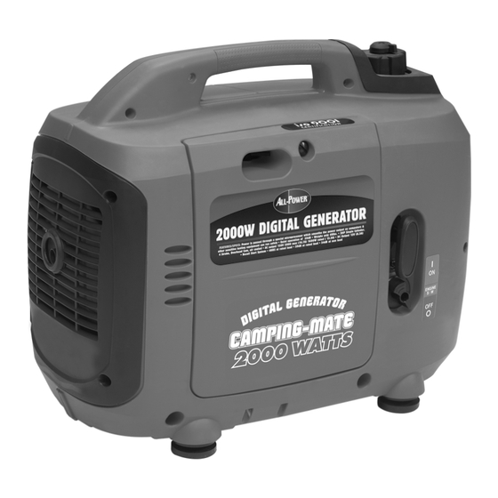
- Page 1 APG3102 Owner’s Manual 2000 WATT DIGITAL GENERATOR Distributed by: ALL-POWER AMERICA ©2005 ALL-POWER AMERICA 16273 E. Gale Ave City Of Industry, California 91745 www.allpoweramerica.com www.allpoweramerica.com...
-
Page 2: Table Of Contents
PREFACE CONTENTS Thank you for purchasing an ALL POWER AMERICA generator. 1. SAFETY INSTRUCTIONS This manual covers operation and maintenance of the 2000 watt digital generator. 2. SAFETY LABEL LOCATIONS All information in this publication is based on the latest product information available at the time of approval for printing. -
Page 3: Safety Instructions
SAFETY INSTRUCTIONS 1. SAFETY INSTRUCTIONS To ensure safe operation -- WARNING To ensure safe operation Gasoline is extremely flammable and explosive under certain conditions. Refuel in a well ventilated area with the engine stopped. WARNING Keep away from cigarette, smoke and sparks when refueling the This generator is designed to give safe and depend- generator, Always refuel in a well-ventilated location. -
Page 4: Safety Label Locations
2. SAFETY LABEL LOCATIONS These lables warn you potential hazards that can cause serious injury. Read the labels and safety notes and precautions described in manual carefully. If a label is lost or becomes unreadable, contact your ALL POWER AMERICA dealer for a replacement. -
Page 5: Component Identification
Control panel 3. COMPONENT IDENTIFICATION E type FUEL CAP VENT LEVER SMART-THROTTLE SWITCH CHOKE LEVER FUEL FILLER CAP OUTPUT INDICATOR LIGHT OVERLOAD INDICATOR LIGHT MAINTENANCE COVER CONTROL PANEL DC RECEPTACLE STARTER GRIP GROUND TERMINAL ENGINE SWITCH DC CIRCUIT PROTECTOR SPARK PLUG OIL ALERT INDICATOR LIGHT MAINTENANCE COVER... - Page 6 A type (120V) Aus type Smart throttle Engine speed is kept at idle automatically when the electrical appliance is disconnected and it returns to the proper speed to power of the electrical load when electrical appliance is connected. This position is recommended to minimize the fuel consumption while in operation.
-
Page 7: Pre-Operation Check
NOTE: The Oil Alert System will automatically stop the engine before the oil level falls 4. PRE-OPERATION CHECK below the safe limit. However, to avoid the inconvenience of an unexpected shutdown, it is still advisable to visually inspect the oil level regularly. WARNING UPPER LEVEL Be sure to check the generator on a level surface with the engine stopped. - Page 8 Fuel tank capacity: 3.7 liter 3. Check the air cleaner. Check the air cleaner element to be sure it is clean and in good condition. FUEL FILLER CAP Loosen the cover screw and remove the left side maintenance cover. Press the latch tab on the top of the air cleaner body, remove the air cleaner cover, check UPPER LIMIT MARK OPEN the element.
-
Page 9: Starting The Engine
3. Move the choke lever to the START position. 5. STARTING THE ENGINE NOTE: Do not use the choke when the engine is warm or the air temperature is high. Before starting the engine, disconnect any load from the AC receptacle. 1.Turn the fuel cap lever fully clockwise to the ON position. -
Page 10: High Altitude Operation
5.Move the choke lever to the RUN position after the engine warms up. High altitude operation At high altitude, the standard carburetor air-fuel mixture will be excessively rich. Performance will decrease, and fuel consumption will increase. High altitude performance can be improved by installing a smaller diameter main fuel jet in the carburetor and readjusting the pilot screws. -
Page 11: Generator Use
CAUTION 6. GENERATOR USE Do not exceed the rated power. The total wattage of all appliances connected must be considered. Be sure to ground the generator when the connected equipment is grounded. Do not exceed the current limit specified for any one receptacle. Do not connect the generator to a household circuit. - Page 12 AC applications Output and Overload Indicators 1. Start the engine and make sure the output indicator light (green) flash. 2.Confirm that the appliance to be used is switched off, and plug in the appliance. The output indicator light (green) will remain flash during normal operating conditions. If the generator is overloaded (in excess of 1.6KVA), or if there is a short in the OUTPUT INDICATOR LIGHT connected appliance, the output indicator light (green) will go OFF, the overload...
- Page 13 DC application WARNING The DC receptacle may be used for charging 12 volt automotive-type batteries only. The zero load voltage is 15V-30V. The battery gives off explosive gases; keep spark, flames and cigarettes away. NOTE Provide adequate ventilation when charging. The battery contains sulfuric acid (electrolyte).
-
Page 14: Stopping The Engine
Oil alert system 7. STOPPING THE ENGINE The oil alert system is designed to prevent engine damage caused by an insufficient amount of oil in the crankcase. Before the oil level in the crankcase falls below a safe limit, the oil alert system will automatically shut down the engine(the engine switch will To stop the engine in an emergency, turn the engine switch to the OFF position. -
Page 15: Maintenance
3. Allow the engine to cool well, and turn the fuel cap lever fully counterclockwise to the 8. MAINTENANCE OFF position. The purpose of the maintenance and adjustment schedule is to keep the generator in FUEL CAP LEVER the best operating condition. Inspect or service as scheduled in the table below. - Page 16 1. CHANGING OIL 2. AIR CLEANER SERVICE A dirty air cleaner will restrict air flow to the carburetor. To prevent carburetor malfunc- tion, service the air cleaner regularly. Service more frequently when operating the Drain the oil while the engine is still warm to assure rapid and complete draining. generator in extremely dirty areas.
- Page 17 3. SPARK PLUG SERVICE 5. Visually inspect the spark plug. Discard it if the insulator is cracked or chipped. RECOMMENTDED SPARK PLUG: A7RTC Clean the spark plug with a wire brush if it is to be reused. 6. Measure the plug gap with a feeler gauge. To ensure proper engine operation, the spark plug must be properly gapped and free of The gap should be 0.6~0.7mm (0.024-0.028in).
-
Page 18: Transporting/Storage
a. Drain all gasoline from the fuel tank into an approved gasoline container. 9. TRANSPORTING STORAGE b. Turn the engine switch ON, and loosen the carburetor drain screw and drain the gasoline from the carburetor into a suitable container. c. With the drain screw loosened remove the spark plug cap, and pull the starter grip 3 To prevent fuel spillage when transporting or during temporary storage, the generator to 4 times to drain the gasoline from the fuel pump. -
Page 19: Troubleshooting
Appliance does not operate: 10. TROUBLESHOOTING Is the output indicator light ON? When the engine will not start: Is there fuel in the tank? Refuel the fuel tank Is the overload in- Take the generator to an dicator light ON? authorized dealer. -
Page 20: Specifications
11. SPECIFICATIONS 12. ELECTRICAL WIRING DIAGRAM SPECIFICATIONS Blue Graz rectifier 2000 Digital Generator Model Brown Charging winding Rated frequency (Hz) Blue Rated voltage (V) 120/240 Black Rated current (A) 13.3/6.7 Yellow Yellow Rated speed (rpm) 5000 Main Blue Rated output (kVA) Green winding Pink... -
Page 21: Light Kit
13. LIGHT KIT MOUNTING INSTRUCTIONS FOR LIGHT KIT M5 45 M5 16 M5 45 Our Light kit is designed specifically for use on this Generator. Tools required: Phillips Screwdriver Fittings supplied: (1) Portable Digital Generator (2) Light Kit Assembly (3) Antiskid Round Nut (4) Antiskid Round Stud (5) Left Mount Plate of Light Kit (6) Right Mount Plate of Light Kit...
Need help?
Do you have a question about the APG3102 and is the answer not in the manual?
Questions and answers