Table of Contents
Advertisement
Advertisement
Table of Contents

Subscribe to Our Youtube Channel
Related Manuals for AC Tech MC1000 series


Summary of Contents for AC Tech MC1000 series
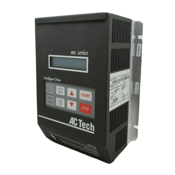
- Page 1 MC1000 Series Installation and Operation Manual...
-
Page 2: Table Of Contents
Manual Number: 1001.013.11 TABLE OF CONTENTS GENERAL....................... 1 PRODUCTS COVERED IN THIS MANUAL..........1 PRODUCT CHANGES..................1 WARRANTY....................1 RECEIVING..................... 1 CUSTOMER MODIFICATION............... 1 MC1000 SPECIFICATIONS......….....………...…..2 MC1000 MODEL DESIGNATION CODE.........…..…..3 MC1000 DIMENSIONS..............…..4 MC1000 RATINGS................…..8 THEORY......................12 DESCRIPTION OF AC MOTOR OPERATION.......... -
Page 3: General
AC Technology Corporation also holds no liability for losses of any kind which may result from this action. Instruction manuals with the most up-to-date information are available for download from the AC Tech website (www.actechdrives.com). -
Page 4: Mc1000 Specifications
MC1000 SPECIFICATIONS Storage Temperature -20° to 70° C Ambient Operating Temperature Chassis -10° to 55° C (With 2.5, 6, and 8 kHz carrier, Type 1 (IP 31) -10° to 50° C derate for higher carriers) Type 4 (IP 65) -10° to 40° C Type 12 (IP 54) -10°... -
Page 5: Mc1000 Model Designation Code
MC1000 MODEL DESIGNATION CODE The model number of an MC1000 Series drive gives a full description of the basic drive unit (see example below). EXAMPLE: M1450BP (MC1000, 480 Vac, 5 HP, Type 1 Enclosure, with a Remote Keypad Assembly) Series:... -
Page 6: Mc1000 Dimensions
MC1000 DIMENSIONS CHASSIS AND TYPE 1 ENCLOSED IF W < 7.86" Conduit Holes: T = 0.20" S Dia. U = 0.34" 0.88" Dia. V = 0.19" 1.00" S Dia. IF W = 10.26" T = 0.28" U = 0.34" Dia. Slot V = 0.24"... - Page 7 DIMENSIONS - CHASSIS AND TYPE 1 ENCLOSED (continued) INPU T VOLT AGE MODEL M1230S 7.50 6.12 5.12 3.77 3.30 1.37 5.50 0.88 240 / 200 M1230 7.50 6.12 5.12 3.77 3.30 1.37 5.50 0.88 480 / 400 M1430 7.50 6.12 5.12 3.77 3.30...
- Page 8 TYPE 4 AND 4X ENCLOSED IF W < 7.86" Conduit Holes: T = 0.20" S Dia. U = 0.34" 0.88" Dia. 1.00" V = 0.19" S Dia. IF W = 10.26" T = 0.28" Dia. Slot U = 0.44" V = 0.24" Mounting Tab Detail INPU T VOLT AGE...
- Page 9 DIMENSIONS - TYPE 4, 4X, AND 12 ENCLOSED (continued) IF W < 7.86" Conduit Holes: T = 0.20" S Dia. U = 0.34" 0.88" Dia. 1.00" V = 0.19" S Dia. IF W = 10.26" T = 0.28" Dia. Slot U = 0.44"...
-
Page 10: Mc1000 Ratings
MC1000 RATINGS The following tables indicate the input and output ratings of the MC1000 Series drive. NOTE: The output current ratings are based on operation at carrier frequencies of 8 kHz and below. At full ambient temperature, operation at carrier frequencies above 8 kHz require derating the drive by multiplying the output current rating by the following factors: 0.94 at 10 kHz, 0.89 at 12 kHz, and 0.83 at 14 kHz. - Page 11 M1200 SERIES RATINGS INPUT OUTPUT MODEL (240 Vac, 50 - 60 Hz) (0 - 230 Vac) NOMINAL NOMINAL MODEL CURRENT CURRENT NUMBER RATED INPUT (AMPS) POWER (AMPS) POWER PHASE (KVA) (KVA) (NOT E 1) (NOT E 2) (NOT E 2) M1205S M1205 M1210S...
- Page 12 M1400 SERIES RATINGS INPUT INPUT INPUT INPUT OUTPUT OUTPUT OUTPUT OUTPUT MODEL MODEL (480 Vac, 50 - 60 Hz) (480 Vac, 50 - 60 Hz) (0 - 460 Vac) (0 - 460 Vac) MODEL MODEL (480 Vac, 50 - 60 Hz) (480 Vac, 50 - 60 Hz) (0 - 460 Vac) (0 - 460 Vac)
- Page 13 M1500 SERIES RATINGS INPUT OUTPUT MODEL (590 Vac, 50 - 60 Hz) (0 - 575 Vac) NOMINAL NOMINAL MODEL CURRENT CURRENT NUMBER RATED INPUT (AMPS) POWER (AMPS) POWER PHASE (KVA) (KVA) (NOT E 1) (NOT E 2) (NOT E 2) M1510 M1520 M1530...
-
Page 14: Theory
THEORY DESCRIPTION OF AC MOTOR OPERATION Three phase AC motors are comprised of two major components, the stator and the rotor. The stator is a set of three electrical windings held stationary in the motor housing. The rotor is a metal cylinder, fixed to the motor drive shaft, which rotates within the stator. - Page 15 If the frequency applied to the motor is increased while the voltage remains constant, torque capability will decrease as speed increases. This will cause the horsepower capability of the motor to remain approximately constant. Motors run in this mode when operated above base speed, where drive output voltage is limited by the input line voltage.
-
Page 16: Drive Function Description
100% 100% % SPEED “Variable torque” refers to the fact that the torque required varies with the square of the speed. Also, the horsepower required varies with the cube of the speed, resulting in a large reduction in horsepower for even a small reduction in speed. It is easily seen that substantial energy savings can be achieved by reducing the speed of a fan or pump. - Page 17 6.2.1 DRIVE OPERATION Incoming AC line voltage is converted to a pulsating DC voltage by the input diode bridge. The DC voltage is supplied to the bus filter capacitors through a charge circuit which limits inrush current to the capacitors during power-up. The pulsating DC voltage is filtered by the bus capacitors which reduces the ripple level.
- Page 18 6.2.4 MC1000 ANALOG OUTPUT SIGNALS There are two terminals that can supply analog output signals proportional to output frequency or load. Terminal TB-10A can provide a 0-10 VDC or a 2-10 VDC signal proportional to output frequency, and TB-10B can provide the same signals proportional to load.
- Page 19 / FAULT INVERSE FAULT - The relay energizes when the drive “trips” into a fault condition, and remains energized until the fault condition is cleared. LOCK FAULT LOCKOUT - This relay is used when the drive is programmed to automatically restart after a fault. The relay energizes when input voltage is applied to the drive and remains energized until the drive has faulted and unsuccessfully attempted five restarts, or input voltage is removed.
-
Page 20: Installation
Contaminating the drive with metal chips can cause drive failure and will void the warranty. The MC1000 Series is UL approved for solid state motor overload protection. Therefore, a separate thermal overload relay is not required for single motor applications. - Page 21 INSTALLATION AFTER A LONG PERIOD OF STORAGE WARNING! Severe damage to the drive can result if it is operated after a long period of storage or inactivity without reforming the DC bus capacitors! If input power has not been applied to the drive for a period of time exceeding three years (due to storage, etc), the electrolytic DC bus capacitors within the drive can change internally, resulting in excessive leakage current.
-
Page 22: Input Ac Requirements
INPUT AC REQUIREMENTS WARNING! Hazard of electrical shock! Disconnect incoming power and wait three minutes before servicing the drive. Capacitors retain charge after power is removed. INPUT AC POWER REQUIREMENTS 8.1.1 VOLTAGE: The input voltage must match the drive’s nameplate voltage rating. Voltage fluctuation must not vary by greater than 10% overvoltage or 15% undervoltage. -
Page 23: Voltage Selection
Minimum voltage rating of the protection device should be 250 Vac for 240/120 Vac and 240/200 Vac rated drives, and 600 Vac for 480/400 Vac and 590/480 Vac drives. Current limiting type fuses should be used when input fusing is required. Select fuses with low I T values, rated at 200,000 AIC. -
Page 24: Power Wiring
10.0 POWER WIRING WARNING! Hazard of electrical shock! Disconnect incoming power and wait three minutes before servicing the drive. Capacitors retain charge after power is removed. Note drive input and output current ratings and check applicable electrical codes for required wire type and size, grounding requirements, overcurrent protection, and incoming power disconnect, before wiring the drive. -
Page 25: Mc1000 Power Wiring Diagram
11.0 MC1000 POWER WIRING DIAGRAM L1 L2 N T 1 T 2 T 3 L1 L2 L3 120 Vac SINGLE PHASE INPUT WIRING DIAGRAM L1 L2 N 240 Vac SINGLE DISCONNECT PHASE INPUT MEANS WIRING DIAGRAM THREE PHASE (REQUIRED) AC MOTOR FUSED INPUT VOLTAGE WARNING! -
Page 26: Initial Power Up
12.0 INITIAL POWER UP WARNING! Hazard of electrical shock! Wait three minutes after disconnecting incoming power before servicing drive. Capacitors retain charge after power is removed. Before attempting to operate the drive, motor, and driven equipment be sure all procedures pertaining to installation and wiring have been properly followed. WARNING! Severe damage to the drive can result if it is operated after a long period of storage or inactivity without reforming the DC bus capacitors! - Page 27 If the display does not appear, remove the incoming power, wait three minutes for the bus capacitors to discharge, and verify correct installation and wiring. If the wiring is correct, re-apply incoming power and note the display for drive status. If the display still does not appear contact the factory for assistance. NOTE 1: If the drive's display is blank after power up, and it is a model equipped with heatsink fans, check to make sure the fans are operating (they should be spinning anytime power is applied to the drive).
-
Page 28: Keypad Control
13.0 KEYPAD CONTROL The drive can be operated in a number of different ways: keypad (LOCAL), control devices wired to the terminal strip (REMOTE), serial communications (SERIAL), or a combination of each. The drive should first be operated from the keypad during initial start-up. -
Page 29: Mc1000 Display
13.2 MC1000 DISPLAY The following describes the possible display configurations for the MC1000 Series drive. 13.2.1 MC1000 DISPLAY IN STOP MODE When the drive is in the STOP mode, there are three possible displays. The first is the SPEED display, which looks like this: DRIVE SPEED STATUS... - Page 30 The following table shows the possible DRIVE STATUS indications that can appear on the drive display: DRIVE STATUS TABLE DISPLAY DISPLAY DISPLAY DISPLAY DESCRIPTION DESCRIPTION DESCRIPTION DESCRIPTION STOP Drive is in STOP mode - No output to the motor. Drive is in RUN mode and is within + 3 Hz of the speed setpoint. FAULT Drive has shut down due to a FAULT condition.
- Page 31 13.2.2 MC1000 DISPLAY IN RUN MODE When the drive is in the RUN mode, the default display will look like this: DRIVE SPEED STATUS SETPOINT > 60.00 HZ DIRECTION SPEED (FORWARD) UNITS As in the STOP mode, the ENTER key can be used to toggle the display from SPEED to % LOAD to VAC (motor voltage): DRIVE PERCENT...
- Page 32 13.2.3 MC1000 DISPLAY IN FAULT MODE When the drive trips into a fault, the display will automatically change to the FAULT display, which indicates the FAULT MESSAGE: DRIVE FAULT STATUS MESSAGE FAULT: OVERLOAD In FAULT mode, the ENTER key will toggle the display between four screens: FAULT, SPEED, % LOAD and VAC.
- Page 33 The table below shows the possible SPEED REFERENCE SOURCE indications for the auxiliary mode display: SPEED REFERENCE SOURCE TABLE DISPLAY DISPLAY DESCRIPTION DESCRIPTION DISPLAY DISPLAY DESCRIPTION DESCRIPTION KEYPAD - Change speed using the UP and DOWN arrow keys. 0 - 10 VDC analog input at TB-5A. 4 - 20 mA analog input at TB-5B.
-
Page 34: Control Wiring
14.0 CONTROL WIRING 14.1 GENERAL 14.1.1 KEYPAD CONTROL The drive can be controlled by the keypad or by control devices wired to the terminal strip. The drive will run from the keypad “out of the box”, requiring no connections to the terminal strip. Refer to Section 13.0 - KEYPAD CONTROL. 14.1.2 CONTROL WIRING VS. -
Page 35: Start/Stop And Speed Control
14.2 START/STOP AND SPEED CONTROL 14.2.1 REMOTE MODE SELECTION The REMOTE mode can be selected by one of two methods: 1. Program Parameter 30 - CONTROL to REMOTE, or: 2. Program CONTROL to BOTH, set the TB-13A or TB-13C function (see Parameter 47 or 49) to LOCAL SELECT, and DO NOT make a contact closure between TB-13A or TB-13C and TB-2 (making the contact closure will select LOCAL mode). - Page 36 FORWARD and REVERSE ROTATION Select REMOTE mode (see above). Program Parameter 27 - ROTATION to FWD & REV to allow rotation in both directions. Program Parameter 49 - TB13C to START REVERSE. This will force TB- 12A to act as START FORWARD. Select the desired rotation by closing the appropriate terminal (TB-12A for forward, or TB-13C for reverse) to TB-2.
- Page 37 FORWARD and REVERSE ROTATION with ONE RUN CONTACT Follow 1-3 above and wire a normally open maintained contact between TB- 2 and the common of a single-pole, double-throw toggle switch. Wire the poles of the toggle switch to TB-12A and TB-13C. Select the desired rotation with the toggle switch.
- Page 38 FORWARD and REVERSE ROTATION with ONE START CONTACT Follow 1-4 above and wire a normally open momentary contact between TB- 2 and the common of a single-pole, double-throw toggle switch. Wire the poles of the toggle switch to TB-12A and TB-13C. See the wiring diagram in Section 15.3.
- Page 39 In REMOTE mode (terminal strip start/stop control), speed control is only selected using the TB-13 input selects. For AUTOMATIC speed control, one of the TB- 13 input selects must be set to the desired speed reference, and that terminal must be closed to TB-2.
- Page 40 NOTE: If TB-13A, TB-13B, and TB-13C are all programmed to select speed references, and two or three of the terminals are closed to TB-2, the higher terminal has priority and will override the others. For example, if TB-13A is programmed to select 0-10VDC, and TB-13C is programmed to select PRESET SPEED #3, closing both terminals to TB-2 will cause the drive to respond to PRESET SPEED #3, because TB-13C overrides TB-13A.
-
Page 41: Mc1000 Control Wiring Diagrams
15.0 MC1000 CONTROL WIRING DIAGRAMS 15.1 MC1000 TERMINAL STRIP Shown below is the terminal strip on the main control board, along with a brief description of the function of each terminal. Wiring shown above the terminal strip indicates internal wiring on the main control board. FORM C RELAY 16 17 18... -
Page 42: Two-Wire Start/Stop Control
15.2 TWO-WIRE START/STOP CONTROL Shown below is the wiring diagram for a typical two-wire start/stop control scheme, using one maintained contact (such as that from a PLC) for RUN and STOP commands. Close the contact to RUN, and open the contact to STOP. Also shown is the wiring for a 0-10 VDC or 4-20 mA speed reference signal. -
Page 43: Three-Wire Start/Stop Control
15.3 THREE-WIRE START/STOP CONTROL Shown below is the wiring diagram for a typical three-wire start/stop control scheme, using momentary contacts (such as pushbuttons) for START and STOP commands. Also shown is the wiring for a 0-10 VDC or 4-20 mA speed reference signal. -
Page 44: Speed Pot And Preset Speed Control
15.4 SPEED POT AND PRESET SPEED CONTROL Shown below is the wiring diagram for a control scheme that utilizes a speed pot and PRESET SPEEDS for speed control, and either a two-wire or three-wire START/STOP circuit: 16 17 18 1 2 5A 5B 6 10A 10B 2 13A 13B 13C 13D 14 15 2 RXA TXB... -
Page 45: Programming The Mc1000 Drive
16.0 PROGRAMMING THE MC1000 DRIVE 16.1 PROGRAMMING THE PARAMETERS The MC1000 keypad serves two purposes: operating the drive when in the LOCAL mode, and programming the parameters for particular applications. The keypad is shown below, along with the display that should appear when the drive is first powered up: STOP >... - Page 46 Once the correct password is entered, the PROGRAM mode will be entered and the first parameter will be displayed, which is Parameter 0 - LINE VOLTS. This is shown below: PARAMETER PARAMETER NAME VALUE LINE VOLTS AUTO CURSOR To scroll through the parameters, use the UP and DOWN arrow buttons on the keypad.
-
Page 47: Parameter Access Using Speed Dial
16.2 PARAMETER ACCESS USING SPEED DIAL SPEED DIAL is used to access parameters quickly using the parameter number. Once accessed, the parameter can be programmed as described in Section 16.1. SPEED DIAL is accessed by pressing the AUTO/MAN key while in the PROGRAM mode. -
Page 48: Parameter Menu
17.0 PARAMETER MENU PARAMETER MENU PARAM. PARAM. PARAM. PARAM. PARAMETER PARAMETER PARAMETER PARAMETER RANGE OF RANGE OF RANGE OF RANGE OF FACTORY FACTORY FACTORY FACTORY NUMBER NUMBER NUMBER NUMBER NAME NAME NAME NAME ADJUSTMENT ADJUSTMENT ADJUSTMENT ADJUSTMENT DEFAULT DEFAULT DEFAULT DEFAULT LINE VOLTS HIGH, LOW, AUTO... - Page 49 PARAMETER MENU CONT’D PARAM. PARAM. PARAM. PARAM. PARAMETER PARAMETER PARAMETER PARAMETER RANGE OF RANGE OF RANGE OF RANGE OF FACTORY FACTORY FACTORY FACTORY NUMBER NUMBER NUMBER NUMBER NAME NAME NAME NAME ADJUSTMENT ADJUSTMENT ADJUSTMENT ADJUSTMENT DEFAULT DEFAULT DEFAULT DEFAULT SLIP CMP .0 - 5.0 % .0 % TORQUE...
- Page 50 PARAMETER MENU CONT’D PARAM. PARAM. PARAM. PARAM. PARAMETER PARAMETER PARAMETER PARAMETER RANGE OF RANGE OF RANGE OF RANGE OF FACTORY FACTORY FACTORY FACTORY NUMBER NUMBER NUMBER NUMBER NAME NAME NAME NAME ADJUSTMENT ADJUSTMENT ADJUSTMENT ADJUSTMENT DEFAULT DEFAULT DEFAULT DEFAULT TB13A NONE, 0-10VDC, 4-20MA, NONE SPEED#1, LOC SEL,...
-
Page 51: Description Of Parameters
18.0 DESCRIPTION OF PARAMETERS 0 LINE VOLTS (LINE VOLTAGE) This parameter calibrates the drive for the correct input voltage, and can be set to AUTO, HIGH, or LOW. When set to AUTO, the drive measures the DC bus voltage when power is applied and automatically calibrates itself according to the measured value (DC bus voltage is equal to input voltage multiplied by 1.4). - Page 52 The preset speeds can only be set to values that are within the operating range defined by the minimum and maximum frequency (see Parameters: 10 - MIN FREQ, and 11 - MAX FREQ). The following table shows how each preset speed is selected using the TB-13 terminals.
- Page 53 8 ACCEL (ACCELERATION TIME) ACCEL sets the acceleration rate for all speed reference sources (keypad, speed pot, 4-20 mA, 0-10 VDC, jog, and the preset speeds). The ACCEL setting is the time to accelerate from 0 Hz to the BASE FREQUENCY (Parameter 18). The range of adjustment for ACCEL depends on horsepower.
- Page 54 NOTE 1: 240/120 Vac units have the same limits as 240/200 Vac units. NOTE 2: The parameter value can be set below the minimum value shown, but the value shown is the operational limit of the drive. For example, if DECEL is set for 0.1 seconds on a 10 HP, 480 Vac drive without dynamic braking, the actual deceleration time would be 0.5 seconds.
- Page 55 WARNING! Consult motor manufacturer before operating motor above rated frequency. Overspeeding the motor and/or driven equipment can cause damage to equipment and injury to personnel! NOTE: If the drive is equipped with the High Frequency Output option, the range of adjustment will be 1.00 - 650.0 Hz. 12 DC BRAKE (DC BRAKE VOLTAGE) DC braking creates a braking torque by injecting DC voltage into the motor.
- Page 56 13 DC TIME (DC BRAKE TIME) This parameter determines the length of time that the DC braking voltage is applied to the motor. DC TIME should be set to the lowest value that provides satisfactory operation in order to minimize motor heating. NOTE: If this parameter is set to 999.9 seconds (the maximum value), the DC braking will be continuous.
- Page 57 17 MOTOR OL (MOTOR OVERLOAD) The MC1000 Series is UL approved for solid state motor overload protection. Therefore, a separate thermal overload relay is not required for single motor applications. The MOTOR OVERLOAD circuit is used to protect the motor from overheating due to excessive current draw.
- Page 58 NON-COMPENSATED FREQUENCY (Hz) NOTE 1: The above diagram is based on a MOTOR OL setting of 100%. For lower MOTOR OL settings, reduce the % CURRENT values by the same percentage. For example, if MOTOR OL is set to 75%, reduce the % CURRENT values by 25%.
- Page 59 For example, if the drive is rated for 460 Vac output, and the BASE FREQUENCY is set to 60 Hz, the drive will maintain a constant ratio of 7.66 V/Hz (except when AC BOOST or FX BOOST are active, see Parameters 19 and 20) from 0 Hz to 60 Hz.
- Page 60 AC BOOST FX BOOST CONSTANT V/Hz OUTPUT FREQUENCY (Hz) AC BOOST only functions during acceleration. In the diagram above, the drive is operating at 35 Hz and is then commanded to 50 Hz. The output voltage is increased by the AC BOOST setting (approximately 15% in the example above) during acceleration to the new speed setpoint.
- Page 61 CT / NOCMP Use for constant torque applications that require full overload capacity at low speeds (see Parameter 17 - MOTOR OL). 23 CARRIER (CARRIER FREQUENCY) This parameter sets the carrier frequency, or switching frequency of the output IGBT’s. Higher switching rates result in less audible noise to be emitted from the motor, but the efficiency of the drive decreases as the carrier frequency increases.
- Page 62 POWER UP The drive will automatically start upon application of input power. The drive MUST be wired for a two-wire start/stop circuit (refer to Section 14.0 - CONTROL WIRING). The start command MUST be present when power is applied for this function to operate.
- Page 63 27 ROTATION (ROTATION DIRECTION) WARNING! If TB-13C is programmed for RUN REVERSE, TB-1 is disabled and CANNOT be used as a STOP switch! This is true in LOCAL and REMOTE mode. Incorrect use of TB-1 may result in damage to equipment and/or injury to personnel! Refer to Parameter 49 - TB13C for more information.
- Page 64 AUTO The drive will accept a 0-10 VDC input signal on TB-5A and TB-2, a 4-20 mA input signal on TB-5B and TB-2, or one of the four PRESET SPEEDS. The programming of TB-13A, TB-13B and TB-13C determines which AUTO reference is selected.
- Page 65 REMOTE START/STOP and FORWARD/REVERSE commands from the terminal strip only. BOTH LOCAL operation if TB-13A or TB-13C is programmed for LOCAL SELECT and a contact closure is made from TB- 13A or TB-13C to TB-2. If the contact closure is not made, the drive will be in REMOTE mode.
- Page 66 34 LOAD MLT (LOAD MULTIPLIER) This parameter is used to scale the % LOAD display. If the drive output current rating is higher than the motor full load current rating, the drive will not display 100% load when the motor is at full load. Setting this parameter to the ratio (in %) of the drive output current rating to the motor full load current rating will scale the load display to show motor load instead of drive load.
- Page 67 Example 1: The drive is required to operate from 0 to 60 Hz in response to a 0- 5 VDC speed reference signal (rather than the “normal” 0-10 VDC). Because TB5 MAX is based on a 0-10 VDC (or 4-20 mA) signal, the drive will operate at half of the TB5 MAX value if it is given a 5 VDC signal.
- Page 68 44 TB10B OUT (TERMINAL TB-10B OUTPUT) The analog output signal at TB-10B is proportional to the drive load. This parameter selects whether that signal is 0-10 VDC or 2-10 VDC. The 2-10 VDC signal can be converted to a 4-20 mA signal by connecting a resistor in series with the signal such that the total load resistance is 500 Ohms.
- Page 69 48 TB13B (TB-13B INPUT FUNCTION) WARNING! When operating in JOG mode, the STOP key WILL NOT stop the drive. To stop the drive, the contact between TB-13B and TB-2 must be opened. This parameter is used to select the function of terminal TB-13B. Closing TB- 13B to TB-2 activates the TB - 13B function.
- Page 70 0-10VDC Selects 0-10 VDC as the AUTO speed reference input. The 0-10 VDC signal is wired to TB-5A and TB-2. 4-20 MA Selects 4-20 mA as the AUTO speed reference input. The 4- 20 mA signal is wired to TB-5B and TB-2. SPEED#3 Selects PRESET SPEED #3 as the AUTO speed reference.
- Page 71 NOTE: When set to CLEAR, TB-13D becomes the only terminal that can be used to clear a fault (TB-1 will not work). However, the keypad STOP key can still be used to clear faults. 52 TB14 OUT (TB-14 OPEN COLLECTOR OUTPUT) This parameter sets the open-collector output indication for terminal TB-14.
- Page 72 DISABLE Serial communication function is disabled. W / TIMER Enables serial communications with a watchdog timer. If there is no serial activity (read or write) for more than 10 seconds, serial control will turn off and the drive will stop. W / O TIMR Enables serial communications without a watchdog timer.
- Page 73 NOTE 1: The factory default value is 0019. NOTE 2: If PASSWORD is set to 0000, the function is disabled. Pressing the PROG/RUN key will result in direct entry into the PROGRAM mode without having to enter a password. 63 SOFTWARE (SOFTWARE VERSION) This parameter displays the software code and revision number of the control board software.
- Page 74 This parameter is used to reset the programmable parameters back to the factory default settings. This parameter has four possible settings: MAINTAIN Maintain parameter settings as they are. RESET 60 Resets parameters to factory defaults for 60 Hz base frequency. RESET 50 Resets parameters to factory defaults for 50 Hz base frequency.
- Page 75 70 FAULT HISTORY The FAULT HISTORY stores the previous eight fault conditions that caused the drive to trip. The information stored here is view-only, it cannot be altered. The FAULT HISTORY can be used to determine if there is a pattern, or trend, to the faults, which may indicate a problem in the system.
-
Page 76: Troubleshooting
19.0 TROUBLESHOOTING The table below lists the fault conditions that will cause the drive to shut down, as well as some possible causes. Please contact the factory for more information on troubleshooting faults. NOTE: The drive will not automatically restart after a PWR SAG or a CONTROL fault. - Page 77 FAULT MESSAGES FAULT DESCRIPTION POSSIBLE CAUSES PWR SAG Power Sag fault: Control board Erratic AC line. voltage is below tolerance. A new control board has been Perform a factory reset using installed that is different from the Parameter 65-PROGRAM. previous version. This will update the software and allow the fault to be reset.
-
Page 78: User Setting Record
20.0 USER SETTING RECORD PARAMETER MENU: USER SETTING RECORD PARAM. PARAM. PARAM. PARAM. PARAMETER PARAMETER PARAMETER PARAMETER FACTORY FACTORY FACTORY FACTORY USER USER USER USER NUMBER NUMBER NAME NAME DEFAULT DEFAULT SETTING SETTING NUMBER NUMBER NAME NAME DEFAULT DEFAULT SETTING SETTING LINE VOLTS AUTO... - Page 79 PARAMETER MENU: USER SETTING RECORD PARAM. PARAM. PARAM. PARAM. PARAMETER PARAMETER PARAMETER PARAMETER FACTORY FACTORY FACTORY FACTORY USER USER USER USER NUMBER NUMBER NAME NAME DEFAULT DEFAULT SETTING SETTING NUMBER NUMBER NAME NAME DEFAULT DEFAULT SETTING SETTING SLIP CMP .0 % TORQUE CONSTANT CARRIER...
- Page 80 PARAMETER MENU: USER SETTING RECORD PARAM. PARAM. PARAMETER PARAMETER FACTORY FACTORY USER USER PARAM. PARAM. PARAMETER PARAMETER FACTORY FACTORY USER USER NUMBER NUMBER NUMBER NUMBER NAME NAME NAME NAME DEFAULT DEFAULT DEFAULT DEFAULT SETTING SETTING SETTING SETTING TB13C NONE TB13D EXT FAULT TB14 OUT NONE...
- Page 81 Declaration relates, are in conformity with the relevant provisions of the following standards, provided that installations are carried out in accordance with manufacturer’s instructions. PRODUCTS RELATED TO DECLARATION MC1000 Series AC Variable Frequency Motor Drives: M1100 M1200 M1400...
- Page 82 A C Technology Corporation 660 Douglas Street, Uxbridge MA 01569 Sales: 800 - 217 - 9100, FAX: 508 - 278 - 7873 Service: 508 - 278 - 9100 ext 125, FAX: 508 - 278 - 6620...
- Page 83 A C Tech Variable Speed AC Motor Drives MC SERIES DYNAMIC BRAKING and ADDITIONAL FORM C RELAY OPTION INSTALLATION INSTRUCTIONS Manual Number: IMMDBA01 These instructions apply to MC models rated: 0.5 - 5 HP, 240/200 Vac 1 - 7.5 HP, 480/400 Vac 1 - 7.5 HP, 590/480 Vac GENERAL These installation instructions apply to the Dynamic Braking and Additional Form C Relay options available for the MC Series...
- Page 84 The following parts are included with the Dynamic Braking and Additional Form C Relay kits: (1) Dynamic Braking Board (9935-XXX, or 9956-XXX) or Additional Form C Relay Board (9934-XXX or 9956-XXX) (1) 7/16” Nylon sleeve standoff (1) 3/4” Nylon sleeve standoff (2) Nylon “snap-in”...
- Page 85 DIAGRAM A - EXPLODED VIEW 0.5 - 5 HP, 240/200 Vac 1 - 7.5 HP, 480/400 Vac 1 - 7.5 HP, 590/480 Vac SCREW (TYPICAL 4 PLCS.) SHOULDER WASHER (TYPICAL 4 PLCS.) 3/4" STANDOFF 1 5/16" STANDOFF (TYPICAL 3 PLCS.) SHOULDER WASHER LOCATION OF P8 &...
- Page 86 DIAGRAM B RESISTOR CONFIGURATIONS If the Dynamic Braking Kit is ordered separately from the MC Series drive, the resistor assembly will be shipped in the 480 Vac and 590 Vac configuration. Therefore, for 240 Vac units, the resistor configuration must be modified, as shown below, using the hardware included with the kit.
- Page 87 THE MC1000 KEYPAD MC1000 KEYPAD FUNCTIONS MC1000 DISPLAYS Press the START key to start the drive. The START Shown below are examples of MC1000 displays. To scroll through START key is only active in LOCAL mode. the SPEED, LOAD, and MOTOR VOLTAGE displays, press and release the ENTER key.
- Page 88 FAULT FAULT DRIVE NUMBER MESSAGE STATUS NOTE: Before installing and operating the MC1000 drive, please read and become familiar with the MC1000 Series Installation and Operation Manual. I T A 2 OUTPUT ACCEL A C Technology Corporation . T S 660 Douglas St , Uxbridge, MA 01569 NOTE 1: REFER TO THE MC1000 MANUAL.
Need help?
Do you have a question about the MC1000 series and is the answer not in the manual?
Questions and answers